patent · US4000851
Solar-heated dwelling
4 January 1977
Page 1 — bibliographic record
United
Heilemann
States Patent to 11 4,000,851
54). SOLAR-HEATED DWELLING adjusting angle of incidence of exterior light rays from 76) Inventor: Volkmar Heilemann, 127 Mountain the sun to the surface of the collector plate, are View Road, Warren Township, N.J. mounted upon a roof with water flow therefrom being O7060 channelled below an insulated ceiling downwardly for alternate flow as between parallel flow paths alter 22 Filed: Nov. 12, 1975 nately selectively to and through concrete slab conduits (21) Appl. No.: 631,085 having copper tubing directing heated water there through, and the parallel flow conduits through a layer (52) U.S. C. .................... 237/1 A; 126/271; of rocks beneath the concrete slab, the concrete slab 126/400; 165/18; 165/45 being a part of the floor structure of the dwelling and (51 int. C.’............................................ F24, 3/02 the layer of rocks being a reservoir sink therebeneath, 58 Field of Search .................. 126/270,271, 400; flow being directed dependent upon differential tem 237/1 A; 165/45, 18; 62/437, 260 perature of the upper floor surface of the concrete slab, 56) References Cited such that space within supporting wall room space defined between the ceiling and the floor is economi
UNITED STATES PATENTs cally heated devoid of excessive room temperatures 2,559,870 7/1951 Gay ............................... 23711 A X and with substantially level and constant ambient tem 2,680,565 6/1954 Lof .................................... 237/1 A perature ranges as desired and preset within the room 2,693,939 11/1954 Marchant et al................ 165/45 X space over extended periods of time for and throughout 3,262,493 7/1966. Hervey ................. ... 165118 X a heating season of the year, while being inoperative 3,369,541 2/1968 Thomason ......................... 126/271 and non-functional when heat is not desired, and in 3,873,022 3/1975 Hilgemann......................... 237/8 R cluding further a hot-water heating provision embodied Primary Examiner-William E. Wayner within an intermediate heat exchanger located between the solar cells fluid circuit and the concrete slab heat
Assistant Examiner-William E. Tapolcai, Jr. ing circuit, each circuit having its individual circulation 57 ABSTRACT pump controlled by its respective thermostat. In a preferred embodiment of the invention, rotatably adjustable elongated cylindrical solar collector plate cells, rotatable around the elongated axis thereof for 10 Claims, 5 Drawing Figures
12 eye Arara Lea SS SSS
goes
Page 2
Drawing sheet — no readable text.
Page 3
Drawing sheet — no readable text.
Page 4
Other objects become apparent from the preceding
SOLAR-HEATED DWELLING and following disclosure.
This invention is directed to a novel solar heating unit One or more objects are obtained by the invention as for an office or home dwelling, as well as schools and defined herein.
Broadly the invention may be defined as a solar heat
BACKGROUND TO THE INVENTION ... ing unit in the form of a dwelling such as an office or home, of which the building structure includes a partic
Prior to the present invention, there have been major ular floor structure and combination, wall structures difficulties and disadvantages associated with the solar positioned to define the dwelling space immediately homes built thus far built by leading proponents of 10 above the floor structure combination, a particular solar heating. For example there is the electrical energy ceiling structure combination, a particular roof struc of the running of pumps of the current systems, which ture and combination, together with a solar heating because of inefficient heating by radiators and the like, system for harnessing heat energy from the sun light and because of inadequate provisions for heat reser rays and for transferring the heat energy to the particu voirs, and the like, nevertheless involve great expense 15 lar floor structure combination by forced circulation. for the electrical energy consumed by such pumps; In various preferred embodiments, the particular floor moreover, the need for supplemental heating is exten combination includes a heat sink-reservoir of rocks sive in most cases because of the inadequate heat reser below and in conductive contact with a concrete slab voirs, as well as because the prior systems are func floor thereabove having heat flow conduit spaces ex tional only when the water within the reservoir tank is 20 tending therethrough with typically and preferably relatively high in temperature, because of the excessive copper piping embedded therein for circulation of the heat loss in the circulating of the water to the radiator fluid to and from the solar cells. Preferably also, there or equivalent heating units within the rooms of the is a parallel flow conduit system to that flowing through dwelling. Additionally, control - rather the lack of the concrete slab, the parallel flow extending as by control - of heat within a desired temperature range 25 copper tubing, through the rock layer, with a valve independent of major changes in outdoor daily temper thermostatically controlled by upper surface tempera atures, has constituted a major problem, the system ture of the concrete slab, to divert flow to and from the tending to overheat beyond need in hot weather, while conduits of the concrete slab depending upon the tem providing inadequate and/or delayed heat during cool perature thereof, being diverted to the reservoir when weather. Also, during hot weather of summer, prior 30 ever the upper surface of the concrete slab exceeds a solar units have resulted in excessive attic heat, addi predetermined temperature as might be desired and tionally normally requiring an attic fan to evacuate hot preset selectively, until such temperature decreases air therefrom resulting from over-heated roof struc below another preset selected minimum. The preferred ture, which excessive heat also is detrimental to the solar cells employed are the same inventor's cylindrical structure of the dwelling itself. Increased cost of elec 35 rotatable collector-plate cells intermittently adjustable trical energy, in the light of all of these difficulties, in angle of incidence from time-to-time through the seriously detracts from prior systems, for solar heating. year, for example, to obtain optimum efficiency by SUMMARY OF THE INVENTION most direct (perpendicular, for example) sun rays, and having the desired and preferred insulation beneath the
Accordingly, objects of the present invention include 40 collector plate, such that the respective cells in fact, the overcoming and/or avoiding of disadvantages and while collecting solar heat, simultaneously insulate the disadvantages of the types described above, together roof surface from the heat of the sun as well as from the with the obtaining of novel advantages and innovations. heat of the collector plate of the cell itself, adding to Another object is to obtain a solar-heated dwelling in the efficiency of the cell as well as to the protection of which the intermediate transfer of heat energy is obvi 45 the roof from excessive heat exposure. In a still other ated by direct heating of dwelling space by the heat preferred embodiment, there is provided an intermedi reservoir itself efficiently. - ate heat exchanger as a liquid reservoir, for the pre Another object is to obtain an improved heat-sink ferred water heat transfer media, from which reservior and reservoir having a high potential heat-sink reserve for liquid, there is one pump cycle to and from the solar and durability. 50 cells, with a venting valve which when open causes the Another object is to obviate prior high electricity water to drain to the reservoir, rendering the further demands during heating and summer seasons respec collection of solar heat impossible until the vent is tively. again closed and the pump rebegun. The opening and Another object is to obtain improved control of tem closing of the venting valve and the activation and perature range in the dwelling space being solar heated. 55 deactivation of the solar cell cycle pump are controlled Another object is to obtain improved control over by typically and preferably a common thermostat selectivity of immediate heating versus future heating which vents and turns-off the pump whenever the water by selective storage capability. in the reservoir exceed a selected preset temperature, Another object is to obtain an improved solar-heated and turns-on the pump and closes the venting valve dwelling conservative of heat energy through improved 60 when the heat exchanger reservoir water temperature arrangement of the solar heating elements relative to drops below a selected preset minimum temperature. dwelling structural elements. In another pump cycle to and from the conduits of each Another object is to avoid needless heat loss and to of the pipes of the concrete floor slab and the layer of improve exclusion of unwanted heat, respectively, dur rocks therebeneath, flow is controlled by a pump re ing the alternate winter and summer seasons. 65 sponsive also to the temperature of the uppersurface by Another object is to avoid structural dwelling roof a thermostat, such as the differential thermostat con damage by the improved dwelling structure of this trolling the flow selection of the parallel conduit flows invention. of the concrete floor slab and the rock layer therebe
Page 5
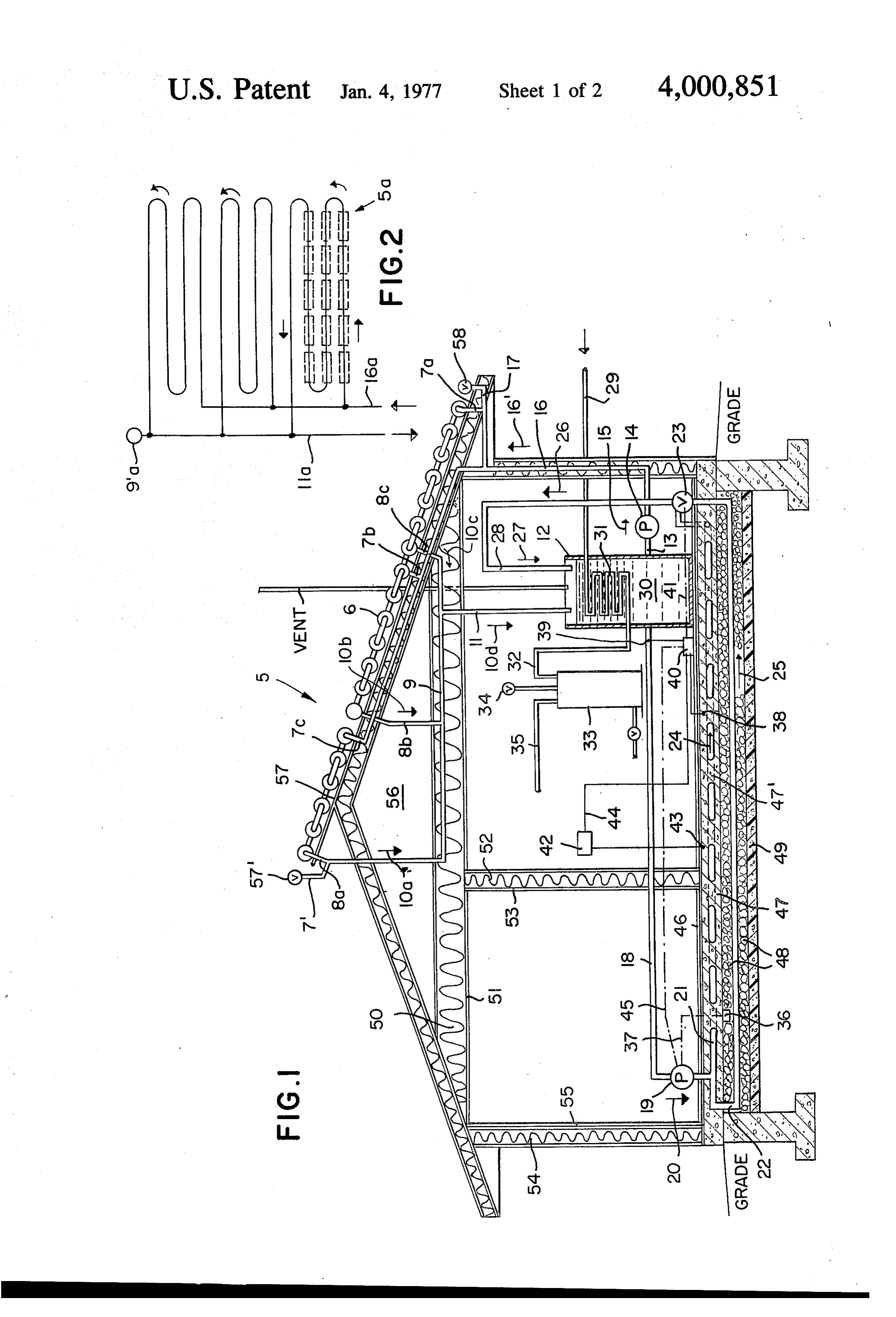
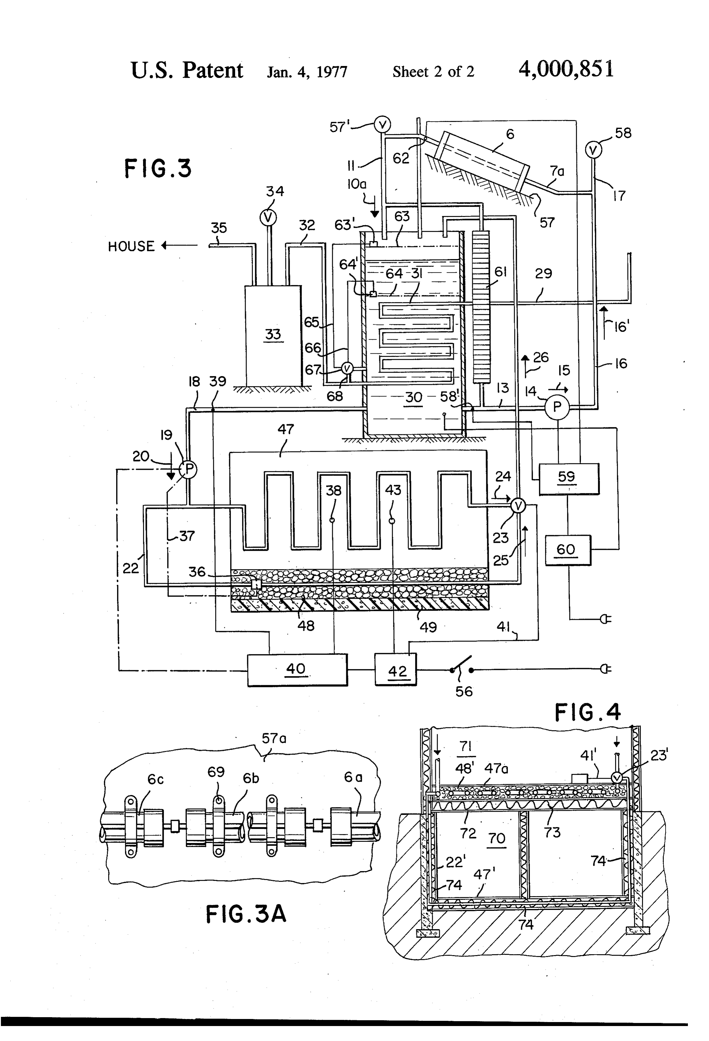
neath. In a further embodiment, the heat exchanger water in pipe 18 as sensed by sensor 39. Thermostatic water reservoir provides a hot-water heating system for sensor 38 causes the valve 23 to direct all or more flow the dwelling by the incorporation of a closed-circuit through pipe 21 when the upper surface of the concrete flow therethrough by which water of a hot water pipe slab 47 drops below a predetermined set temperature, may be heated and fed either directly to a faucet of first and causes the valve 23 to direct more or all flow to to a conventional hot water tank and thereafter con flow through the pipe 22 after the upper surface tem ventionally to the spigots and the like. perature at thermostatic sensor 38 exceeds a predeter In systems including antifreeze or equivalent liquids mined value whereby heat becomes stored in the rocks within the water, or an alternate heat transfer media of 48 preferably of large gravel size, typically, and the any known and/or conventional type, the need for a O peripheral insulation 49 which typically is urethane large heat exchanger reservoir tank may be obviated. foam or the like, prevents any significant heat loss in a Also, as noted previously, such heat exchanger reser downward direction to an exterior of the building struc voir tank is not essential, but is but one preferred em ture, as water flows in direction 25 until valve 23 again bodiment. shifts flow to pipe 21 for again flow in direction 24. The The invention may be better understood by making 5 thermostat (differential thermostat) 40 also in part reference to the following figures. controls the pump 19, turning it on whenever thermo THE FIGURES static sensor 38 senses a predetermined low and also thermostatic sensor 36 turning on the pump whenever
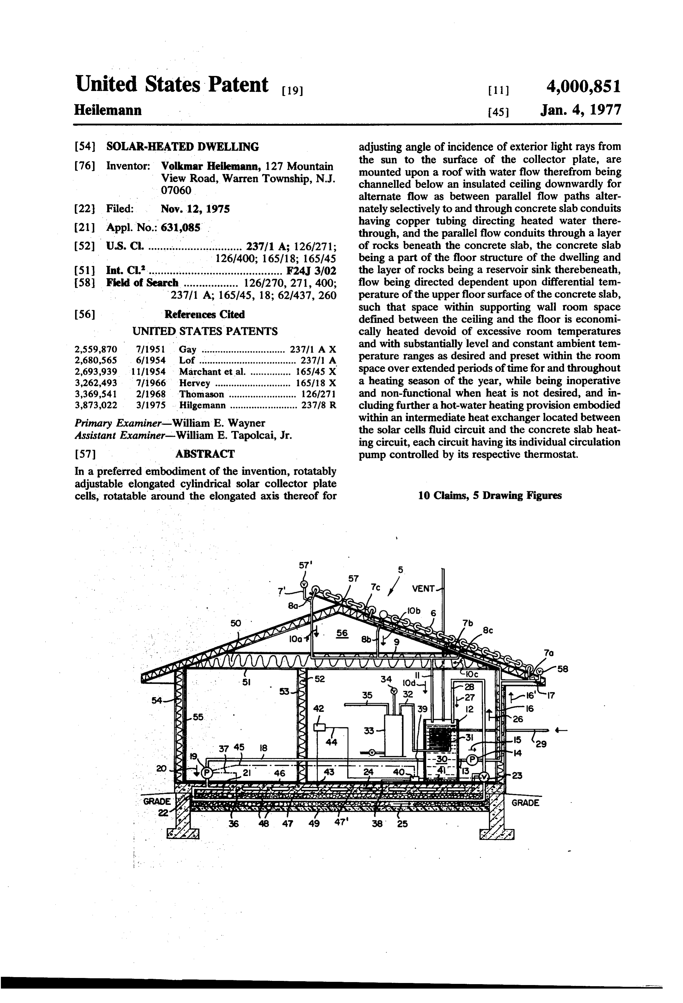
FIG. 1 illustrates in a diagrammatic view, an eleva the temperature of the rocks 48 is below a predeter tion side view with the near side of the house not 20 mined minimum. Pump 19 is off only when both the shown, a preferred embodiment of the solar-heated sensors 38 and 36 are switched to off, whereby the dwelling of the present invention. pump remains running when flow is shunted from pipe FIG. 2 illustrates a typical flow diagram for having 21 to pipe 22. Thermostatic sensor 43 is a safety sensor parallel flows through consecutive series-rows of cells, which causes switch 42 to break circuit if and when the from a common cool inlet pipe and to a common hot 25 temperature of the concrete upper portion exceeds a heat transfer liquid outlet pipe. predetermined dangerous or hazardous temperature, FIG. 3 illustrates a diagrammatic flow and circuitry thereby turning-off power to the system and shutting diagram of a typical embodiment such as typically that down the pump 19. Downflow through the down-pipe of FIG. 1. 11 in direction 10d results in a heating of water in the FIG. 3A illustrates an in-part view in elevation plan, 30 tank to a predetermined temperature at which the of a group of preferred solar cells in flow series, where pump 14 shuts-down as controlled by the differential the cells are of the preferred rotatable types rotatable thermostat 59 which responds differentially to the sig around their elongated longitudinal axes thereof, nals from thermostatic sensors 58 and 62, and turns on adapted such that the angle of incidence of sunlightthe flow when that temperature differential, as com rays is adjustable intermittently. 35 pared to the temperature of outflow water from the FIG. 4 illustrates an in-part view of an alternate em solar cell 6 as typically shown in FIG. 3. bodiment to that of FIG. 1, for example, in a diagram The water tank 33 has the conventional safety vent matic side elevation view with the nearest side cut valve 34 and house-water outlet pipe 35. away, where the lower flow alternate flow is directed Sight-glass 61 permits visual inspection of the water through a lower or basement floor. 40 level within the tank 30. Sensors 63' and 64' sense DETALED DESCRIPTION OF THE INVENTION respectively the turn-off water level 63 and the turn-on water level 64 and these sensors jointly control the
In greater detail, FIG. 1, FIG. 3 and FIG. 3A repre off-on valve 67 through leads 65 and 66, controlling sent a common embodiment, and the embodiment of inlet flow through inlet pipe 68 into the space 30. these Figures include the solar cells arranged in a fash 45 While the primary utility of the present invention ion as typified by the arrangement of FIG. 2. concerns the concept of the “combination' of low Thus, with regard to this first illustrated common temperature utilizable water to adequately heat the embodiment, a system of solar cells 5 is arranged along living spaces of the building by virtue of solar energy a roof 57, with individual cells lying substantially hori supplying only low temperatures during most of the day zontally along the surface of the roof extending length 50 and/or evening hours, in conjunction with the floor wise of the roof, having cell inlet pipes 7a, 7b, 7c and heating unit thereby eliminating the problem of hereto cell outlet pipes 8a, 8b, and 8c collectively channeled fore system of solar heat units which have relied solely through collector pipe 9 and into down-pipe 11 into the upon conventional radiators, base-board heat and the reservoir tank 12 having space 30 with hot-water heat like, the utility is further enhanced by ceiling heavy ing coils 31 to be heated thereby to heat cold water 55 insulation and preferably also both outer and inner entering through source water pipe 29 with an outlet to walls insulations 50 and 54 and 53, respectively, of the the hot water heater tank 33 by the outlet pipe 32. ceiling 51, outer walls 55 and inner walls 53 as typically From the water within space 30, outlet 13 leads cooler identified, retaining acquired heat. As noted hereto water from the tank to pump 13 delivering water by fore-above in the background and objects, because of up-pipe 16 in direction 16' to the safety valve mecha 60 prior solar heating units most of the time having water nism 17 and to the inlets 7a, 7b, etc. Also from the tank in the reservoir tank at too low a temperature to heat space 30 outlet pipe 18 leads the water to pump 19 in the house after heat-loss from pipes during transit to direction 20 through one or both alternate flow-path radiators and the like, large amounts of electricity for pipes 21 and 22, the extent of flow through 21 and 22 pumping as well as large supplemental heating by con being controlled by the flip or butterfly valve 23 which 65 ventional routes has heretofore been necessary, the is controlled by thermostat 40 as dependent upon the inefficiency of the prior solar systems thereby making temperature of the concrete slab 47 as sensed by sensor their desirability much less and in fact the heretofore 38 as well as dependent upon the temperature of the systems being far from adequate and thus less practical
Page 6
and satisfactory, as well as not saving enough in heating 2. A solar heating unit of claim 1, including reservoir costs as to justify the" installation of such a system, conduit means providing for conduit fluid parallel flow much less relying on such in the building of a house. In through said layer of rocks, having a differential ther contrast, the present invention has overcome these mostat and control valve adapted and connected to difficulties, together with other advantages noted divert partial or complete flow to the layer whenever herein above. . . . . . . temperature of said concrete at an upper surface FIG. 2 illustrates a typical set of cells-layout, with the thereof exceeds a first predetermined temperature until inlet pipe 16a and the outlet pipe 11a, and the vent 9'a, temperature drop thereof to a second predetermined arrows illustrating the typical directions of water flow. O temperature such that heat energy in excess of that FIG. 3A illustrates the preferred rotatable solar cells temperature selected for the upper surface of the con in series, are cylindrical and have substantially trans crete is directly into the heat sink of the layer of rocks parent tubular walls and are rotatable intermittently for future thermal conductance to the concrete. around their longitudinal axes in order to best adjust to 3. A solar heating unit of claim 2, in which said solar preferably a perpendicular state the sun rays relative to cells are inclusive of thermal insulation beneath a bot a flat collector plate, such as of the cells 6a, 6b, and 6c 15 tom face of a collector plate adapted such that said roof connected for serial water flow therethrough, while the means is insulated from elevated temperatures result same are supported by brackets 69 on a roof 57a. ing from absorbed radiant energy converted to thermal FIG. 4 illustrates an alternate embodiment in which energy by the collector plate.
basically the lower space 70, beneath upper space 71, is 20 4. A solar heating unit of claim 3, in which the solar substituted for the FIG. 1 space in which rocks 48 are cells are cylindrical rotatable cells having substantially located, the additionally heated space 70 serving to transparent tubular walls, being rotatable around an heat in a supplemental fashion the ceiling 72 and upper elongated axis of the cylindrical length thereof adapted insulation 73 and concrete slab 47a and supported such that angle of incidence of sunlight rays is adjust floor 48". The down-pipe 22' is the by-pass pipe as flow 25 able intermittently.
is shunted thereinto by the shunt valve 23", to heat 5. A solar heating unit of claim 4, including periph lower space floor (concrete slab) 47", typically of a eral insulation, means circumscribingly of an area of basement, but not necessarily basement space. Floor location of said layer of rocks for insulating the heat and walls insulation 74 further retains the heat in this sink reservoir against heat dissipation to exterior of said space as a heat reservoir for accessory heating of the 30 building structure.
above space as already explained. 6. A solar heating unit of claim 5, including heat It is within the scope and spirit of the invention to exchanger means as a part of said solar heating means, make such modifications and changes and substitution for providing intermediate heat exchange between fluid of equivalents as would be apparent to a person of of one cyclic flow to and from the solar cells and other ordinary skill in this field of engineering. 35 fluid of another cyclic flow to and from said floor I claim: means and said reservoir conduit means, comprising 1. A solar heating unit comprising in combination: a separate first and second cyclic conduits, and an ex building structure having floor means for circulating changer vessel having both the first and second cyclic fluid therethrough and for providing a heat-sink reser conduits flowing to and from the exchanger vessel, and voir, and floor means comprising concrete having fluid 40 a first thermostat and pump means for opening flow flow conduits embedded therein, and rocks in a layer circuit of the first cyclic conduit when fluid tempera beneath and in contact with a lower face of said con ture within the exchanger vessel reaches a predeter crete in heat-flow relationship adapted such that the mined minimum, the first cyclic conduit channeling rocks serve as a heat sink together with said concrete flow to the solar cells, and for closing flow circuit of the storing thermal energy over extended periods of time, 45 first cyclic conduit, when temperature within the ex and the building structure having spaced-apart upright changer vessel reaches a predetermined maximum, the wall structures-means for defining an enclosure inhab first thermostat and pump means comprising a vent itable space therebetween mounted on an upper face of valve and a thermostat connected thereto, with the the floor means and supportable of overhead structure, vent valve and thermostat connected thereto being and having ceiling means for providing support for 50 adapted such that upon venting of the valve, fluid be upper structure and for insulating said inhabitable comes drained into the exchanger vessel such that the space, mounted on said upright wall structures-means flow circuit of the first cyclic conduit is thereby closed. above and capping said space, and roof means for pro 7. A solar heating unit of claim 6, including a second viding shelter to the ceiling means and mounted there thermostat and valve means for opening flow circuit of above on said spaced-apart upright wall structures 55 the second cyclic conduit when fluid temperature at means and for providing support for solar cells thereon said upper surface of the concrete drops below a prede above; solar heating means for providing solar cells termined minimum temperature, the second cyclic mounted exterior to said building structure with opera conduit channeling flow to said other cyclic flow, tive exposure thereof to outdoor sunlight source, and adapted such that thermal energy from the heat ex for circulating fluid serially to and through the solar 60 changer is channeled to the fluid-flow conduits of the cells, and therefrom to and through said floor means, concrete whenever temperature is below said predeter and from the floor means back to the solar cells, in a mined minimum temperature for the concrete. substantially closed circulation cyclic flow, adapted 8. A solar heating unit of claim 7, including a second such that heat becomes extracted from the fluid into pump in flow series within said second cyclic conduit the heat-sink-reservoir and thereby provides thermal 65 and actuatable and deactivatable by said second ther heat energy to said inhabitable space for the heating mostat and valve means for turning on the second thereof, and for providing forced circulation in said pump when the flow circuit thereof is open and turning closed circulation cyclic flow. off whenever the flow circuit is closed.
Page 7
9. A solar heating unit of claim 8, wherein said first activatable when said predetermined minimum temper pump is in flow series within said first cyclic conduit ature within the heat exchanger is reached. 10. A solar heating unit of claim 9, including a and actuatable and deactivatable by the first thermo closed-flow conduit extending through interior reser stat and pump means, adapted such that the first pump voir space of said exchanger vessel, having connection is deactivated upon the draining of fluid when venting means for connecting thereto hot water pipe inlet and outlet adapted such that water passed through said takes place, and when temperature within the heat closed-flow conduitskmayck bec heated to hot water. exchanger exceeds a predetermined maximum, and k k
Provenance
- Collection
- Cited prior art
- Original PDF
- patentimages.storage.googleapis.com →
- Filed
- 1975-11-12
- Pages
- 7
- Method
- pdftotext (the PDF's own text layer) + pdftoppm 300dpi page scans
- Source
- Google Patents bibliographic record
- Granted
- 1977-01-04
- Inventors
- Volkmar Heilemann
- Transcribed from
- patentimages.storage.googleapis.com →