patent · US3949732
Solar heated building
13 April 1976
Page 1 — bibliographic record
United States Patent (19) 11, 3,949,732 Reines (45) Apr. 13, 1976 54) SOLAR HEATED BUILDING spherical sectors and cover an arcuate area defined by 76 Inventor: Robert G. Reines, Star Rte. 103, the receipt of usable solar heat energy; consideration Tijeras, N. Mex. 87059 being given to the diurnal and seasonal positions of the sun. Heat collecting fluid is passed in thermal 22 Filed: June 10, 1974 contact with the solar heat collectors and is in circula 21 Appl. No.: 478,341 tion with a heat storage reservoir. Air is passed in thermal contact with the solar heat collector to pre vent overheating when the heat collecting fluid is cut 52 U.S. C. ................ 126/270; 126/271; 237/1 A; off or to provide hot air when the heat storage reser 52/82 voir is fully heated or when the solar heat collector is (51) Int. Cl’............................................. F24, 3/02 warmer than ambient but not hot enough to supply 58 Field of Search.................... 126/270, 271, 400; heat to the heat storage reservoir. The solar heat col 237/1 A; 165/18; 52/82 lectors are segregated by the heat collecting fluid cir culation system piping into discrete arrays each cover 56 References Cited ing about 15 of azimuth arc and each such array is UNITED STATES PATENTS controlled by one or more valves which admits or 2,693,939 l if 1954 Marchant et al............... 126/271 X blocks heat collecting fluid flow. Each of the solar 2,713,252 7/1952 Jackson et al........................ 165/18 heat collector arrays and the heat reservoir is provided 2,820,990 lf 1958 Johnson............ ... 52182 X with a temperature sensor. A temperature comparison 2,907,318 10/1959 Awot.................................. 126/271 device compares the temperature of each of the solar 3,236,294 2/1966 Thomason ............... ... 126,400 X collectors with the temperature of the heat reservoir 3,244, 186 4/1966 Thomason et al....... ... 126/270 X to automatically open the valves to only such arrays as 3,250,269 5/1966 Sherock.............................. 126/271 will supply heat to the heat reservoir. The air circula 3,763,608 10/1973 Chamlee....... ... 52182 X tion system through the solar heat collectors is auto 3,831,581 8/1974 Baseley............................... 1261270 matically activated for cooling when the solar heat
Primary Examiner-Kenneth W. Sprague collectors are not being used for heat storage. When Assistant Examiner-James C. Yeung air is passed through the solar heat panels, the heated Attorney, Agent, or Firm-Henry Heyman air may be used to directly provide hot air for space conditioning or other purposes and thereby conserve 57 ABSTRACT the stored heat. The dual-mode capability of air-fluid A solar heated building of generally hemispherical operation enables the system to extract the maximum shape which supports on its surface solar heat collec amount of solar energy for usable purposes. tors. The solar heat collectors are in the shape of 17 Claims, 12 Drawing Figures
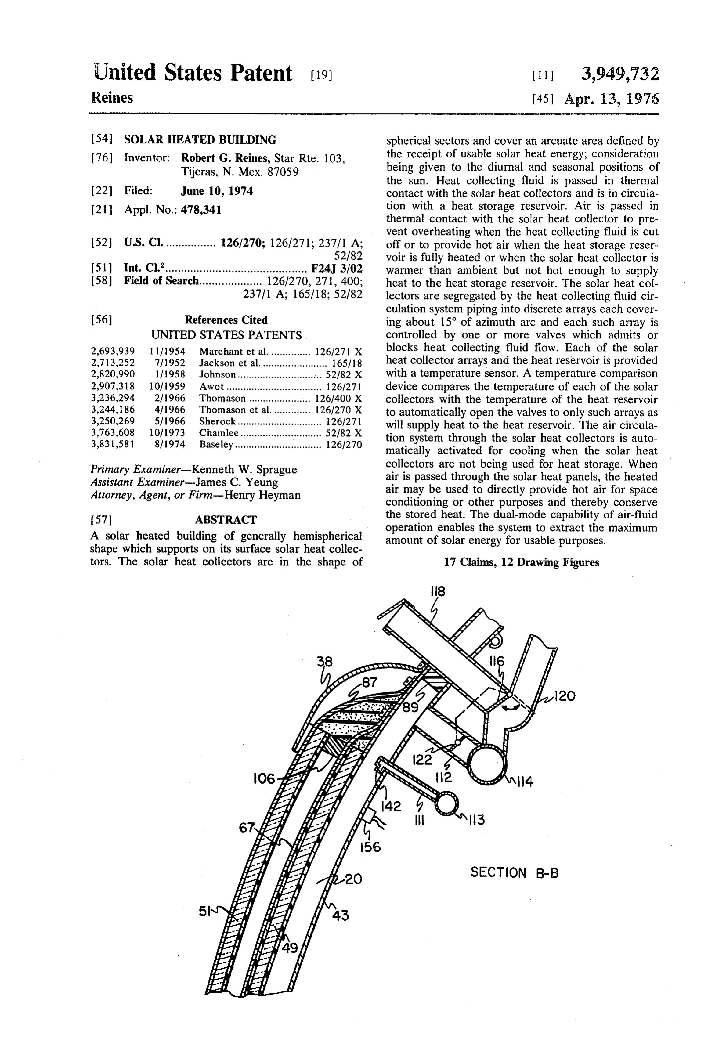
SECTION B-B
Page 2
Drawing sheet — no readable text.
Page 3
Drawing sheet — no readable text.
Page 4
Drawing sheet — no readable text.
Page 5
Drawing sheet — no readable text.
Page 6
Drawing sheet — no readable text.
Page 7
piping, reducing the amount of insulation needed for
SOLAR HEATED BUILDING piping, etc., are such that if the dome shaped building SUMMARY OF THE INVENTION is already constructed or is made of non-conducting materials such as concrete or composition, the solar
This invention relates to a solar energy heated build heat collecting panels of the present invention can be ing of dome or hemispherical shape, which shape is affixed to the exterior surface of the building with few, particularly advantageous for the utilization of an arcu if any, other changes.
ate arrangement of vertical sectors of the exterior wall Another aspect of the present invention is provision for the collection and conversion to heat of solar en for controlled ventilation. The usual dwelling structure ergy. The vertical cross-sectional shape of such dome 10 has enough leakage of air between indoors and out shaped buildings is advantageous in the collection of doors to provide adequate oxygen for life support. The solar heat regardless of the difference in elevation of building of the present invention is essentially non the sun due to seasonal effects and geographical lati leaky so that provision is made for a fail-safe, con tude of installation. trolled system for proper ventilation. The horizontal circular shape enables the sun to be 15 The heat accumulator utilized in the present inven tracked on a daily basis. Only that portion of each tion is of the volume water type housed in an insulated sector is utilized as a solar heat collector which has an heat storage reservoir and preferably is connected di angle of exposure to the sun adequate to provide effec rectly to space heaters without the intervention of a tive collection of solar energy. Thus the solar heat 20 heat exchanger. For other hot water purposes, a heat collectors are actually frusto-sector shaped. Heat con ducting fluid is gated on to only those solar heat collec exchanger water supply is used to eliminate the drain on the soft needed for the solar heat collectors.
tors which collect heat from the sun rapidly enough to The solar heat collecting structure is applicable as contribute heat to a heat reservoir. Automatic means the source of heat for conventional type buildings. A are provided to air cool such solar heat collectors as are 25 dome shaped or inclined faceted structure is mounted not being supplied with fluid for heating the reservoir if the temperature of the solar heat collector approaches proximate type building and preferably on top of the conventional in order to facilitate the liquid plumbing a damaging level.
The dome shaped building is preferably fabricated sun tracking solarsystems.
and air ducting heater
Additionally, the automatic of the present invention can from vertical sectors each of which has a rectangular 30 be installed on top an insulated water tank to supply rib extending along the vertical median line and which hot water for a community.
together with interlocked adjacent sectors shares a like rectangular rib on each of its vertical edges with the DETAILED DESCRIPTION OF THE INVENTION said adjacent sectors. Other features, objects and advantages of the inven The solar heat collecting panels are fabricated di 35 tion will become apparent from reading the following rectly on the dome shell sectors by applying black paint detailed description of the invention with reference to between the ribs and supporting at least one transpar ent cover on the ribs. The preferred number of super the accompanying drawing which shows by way of posed transparent covers are two which are substan illustration and not limitation, a building utilizing the tially hermetically sealed to each frusto sector by firm 40 invention.
In the drawing:
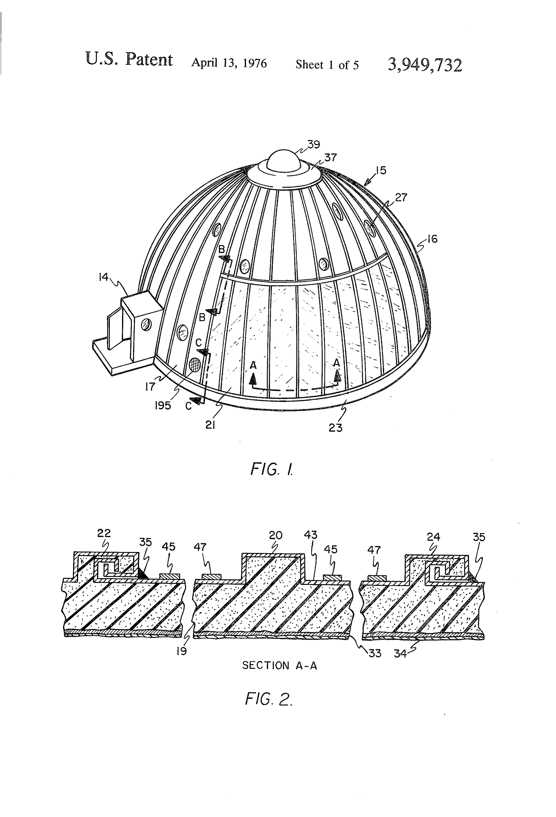
but slidable fastening means. The fastening means ad mits of limited slidability between the transparent ofFIG. a 1 is a side perspective view of one embodiment dwelling in accordance with the invention.
sheets and the sector ribs to allow for differences in thermal coefficients of expansion therebetween. FIG. 2 is a foreshortened horizontal cross section The solar heat collecting panels are arranged to re taken along section A-A of FIG. 1 to show the shell ceive a film or thin sheet of water at the top from con 45 sectors, the joints between them and the solar heat trolled valves and to drain at the bottom by gravity into collecting panel.
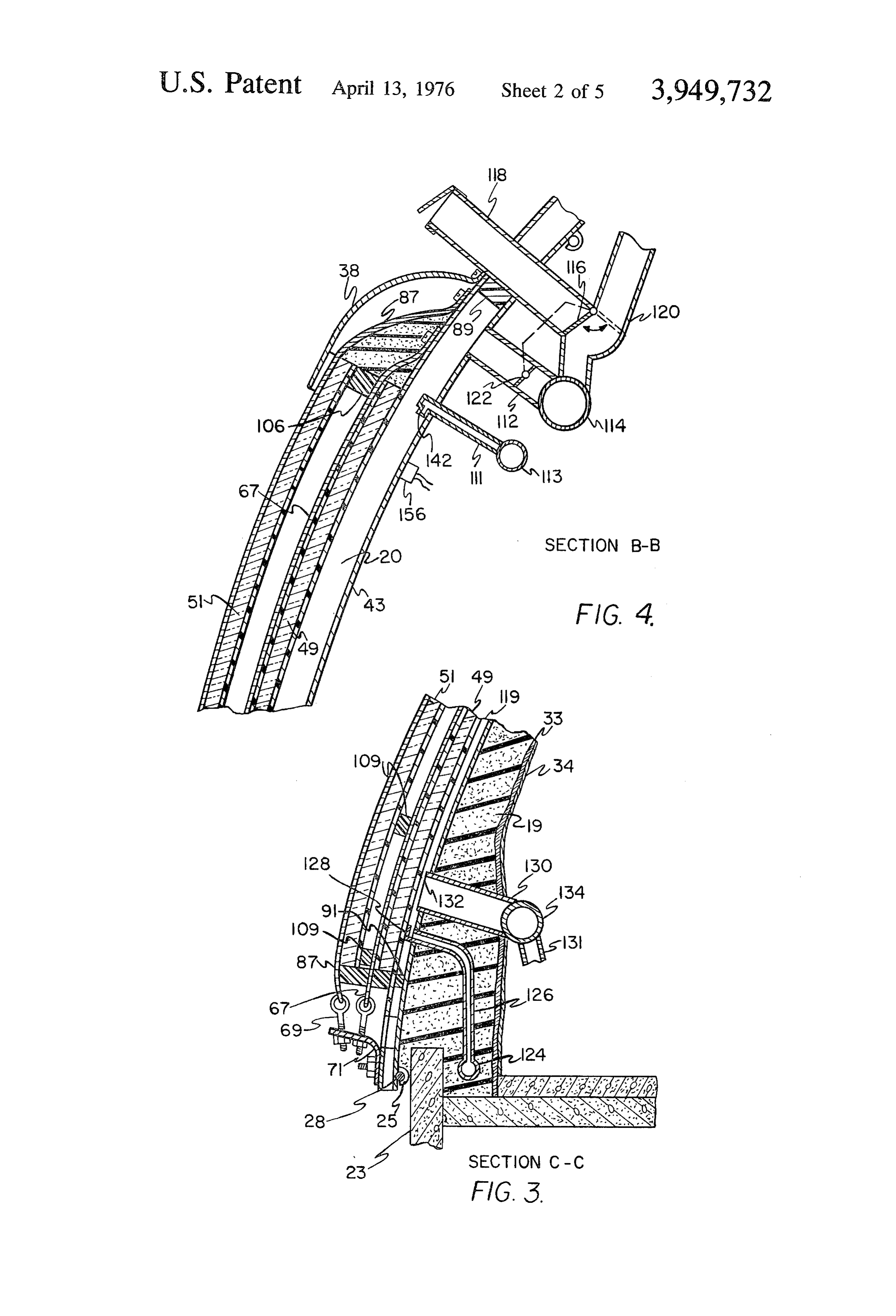
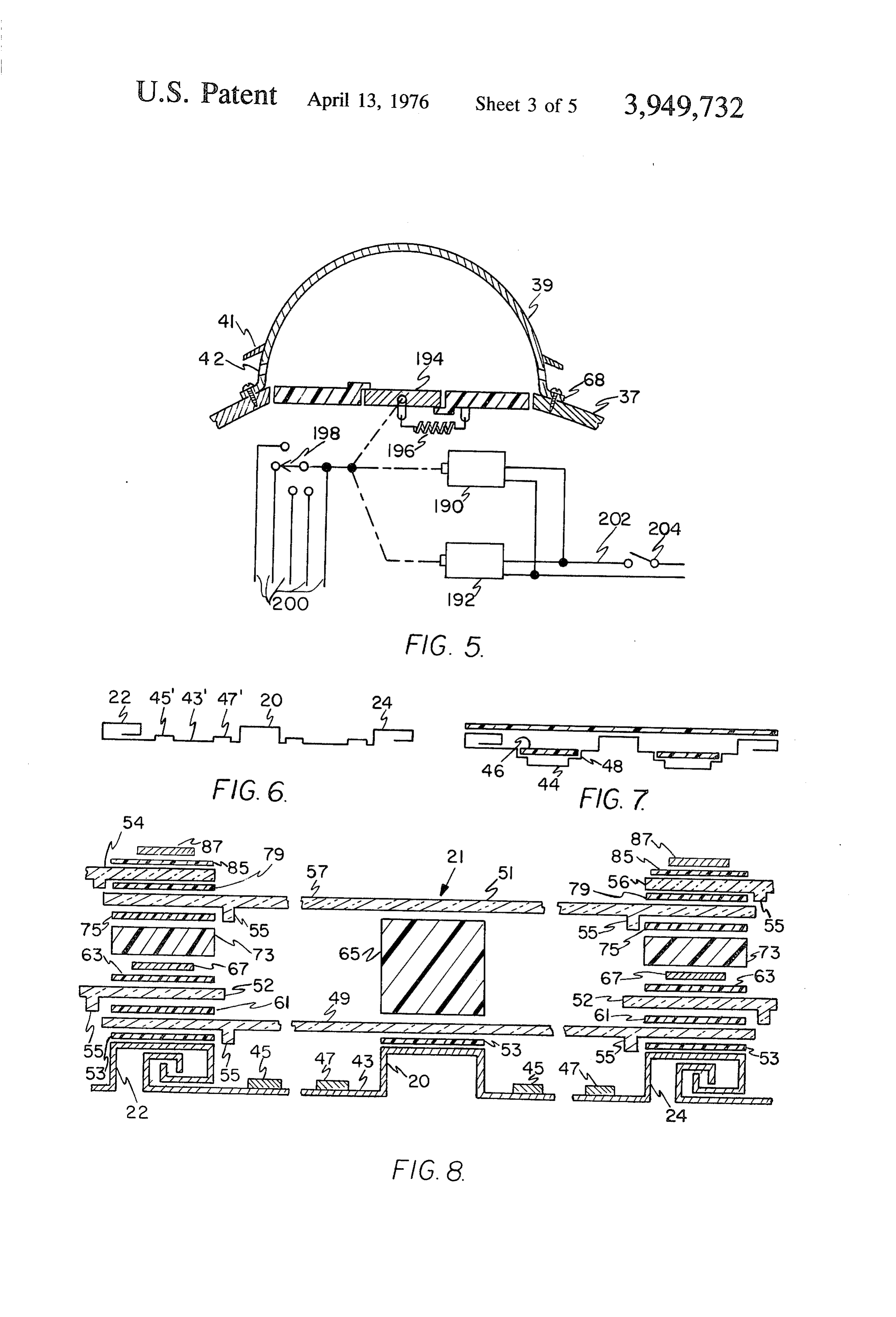
FIG. 3 is a vertical diametric cross section of a lower a common manifold which connects with a heat reser voir. Thus the solar heat collecting panels are always wall portion to show construction, and solar heat col drained when not in use whereby “freezing' problems lecting panel details taken on section C-C of FIG. 1. are eliminated. Tracking of the sun is accomplished by 50 FIG. 4 is a vertical diametric cross section of a wall sensing the temperature of the panels and the tempera portion at the upper end of the heat panels to show heat ture of the heat reservoir and valving heat conductive panel and ducting details taken on section B-B of FIG. fluid into those panels hot enough to supply heat to the 1. FIG. 5 is a vertical diametric cross section of the heat reservoir. The valves may be controlled by a clock 55 mechanism but the temperature sensing method of the central part of the roof, ventilation cap and ventilation present invention is preferred because it has the impor structure details.
tant advantage of most effective use of the solar heat FIG. 6 shows a horizontal cross section of a modified collecting panels for the maximum collection of solar form of solar heat collecting panel. energy. For example, if the temperature of the heat FIG. 7 is a horizontal cross section of another modifi reservoir is low, a substantial plurality of solar heat 60 cation of solar heat collecting panel construction. collecting panels will be activated. As the temperature FIG. 8 is a horizontal cross section of a solar heat of the reservoir rises, only those solar heat collecting collecting panel with certain details disproportionately panels having adequate temperature remain activated. enlarged for clarity.
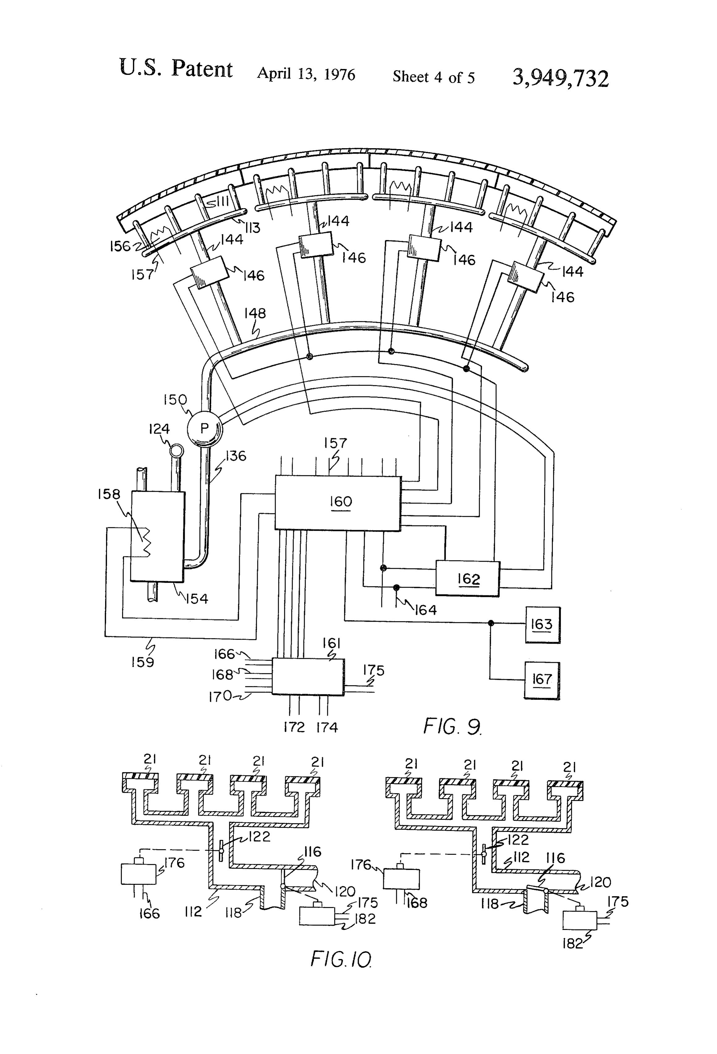
The preferred type of solar heat collecting panel is of FIG. 9 is a schematic drawing of solar heat collecting the type above described; that is, the dome shell sec 65 panel tracking details.
tors, if made of metal are directly used as the radiation FIG. 10 is a diagrammatic drawing of an air flow receiving surface. However, the advantages of the system showing solar heat collecting panel protective dome shape such as, for tracking, reducing length of and hot air generating details.
Page 8
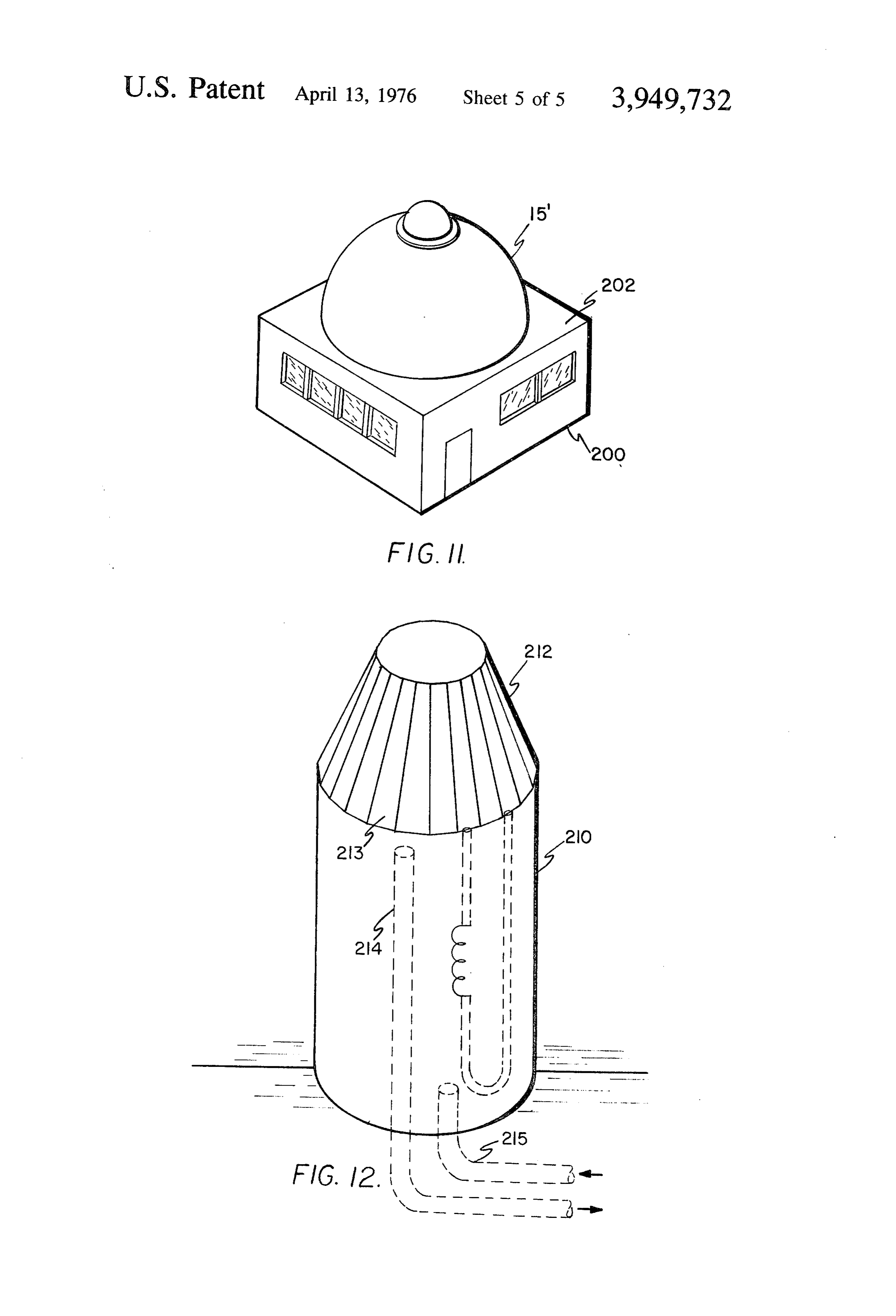
FIG. 11 is a solar heat collection system of the pres slippage and at the same time produces a rectangular ented invention as associated with a generally conven rib configuration capable of hermetic sealing as by a tional type building. fillet of flexible caulk 35. FIG. I2 is a solar heat collection system in accor 5 Proximate the top of the dome, a ventilating cap 39 is dance with the present invention but of polygonal form affixed.
as applied to a hot water storage tank. A rain shield 41 is affixed to the outer surface of the The dome shaped building 15 is shown in FIG. 1, with ventilating cap 39 thereby providing with ventilating portions shown in FIGS. 2, 3 and 4, includes an outer cap apertures 42, passages for ventilating air, as shown hemispherical shell 16 constructed of interlocking sec 10 in F.G. 5.
tor panels 17 to which is attached an inner wall of Solar energy collecting panels 21 are shown in cross insulation 19. Each sector panel has on both its elon section in FIGS. 3, 4 and 8. The heat collecting fluid gated edges a reentrant channel for interlocking with flows downward over the surface of panel 43. Panel 43 adjacent sector panels. Each sector panel also has an differs from non-heat collecting panels in that its outer outwardly projecting middle rectangular reinforcing rib surface is coated with black heat absorbing paint. The 20 along its vertical median line. Each of the sector 5 amount of fluid passed over the panel surface is limited panel vertical edge reentrant channels when assembled by the fluid temperature desired and the rate of heat to adjacent sector panels provide outwardly projecting collection by the panel. The fluid, if liquid, is generally rectangular ribs 22 and 24 similar in configuration to a very thin sheet if it covers the entire width of the heat the middle rectangular rib 20. panel. With such a very thin sheet of fluid, it is very Shell sector panels along an arc profitably exposed to 20 difficult to prevent channeling; that is, the fluid tends to the sun, such as on the southeastern and south expo convert from a sheet to riverlets which have inadequate sures of the building are utilized as the heat collecting thermal coupling with the surface of the panel. To the members for solar heat collectors 21. end that the stream of fluid be a continuous sheet of The assembled shell rests on and is anchored to a adequate width to give good thermal coupling with the foundation or footing 23 of any suitable material such 25 panel, vertical confining and guiding dams 45 and 47 as concrete. One practical method for securing the are affixed to the surface of the panel. Each water shell to the foundation utilizes bolt-hooks 25 shown in confining channel can be delineated by various means, FIG. 3 which engage an annular metal ring 28. Ring 28 and alternatives are shown in FIGS. 6 and 7. The dams is constricted by a turnbuckle or the like (not shown) 30 shown in FIG.8 may be plastic material magnetic strips against the outer surface of footing 23. of a type commercially available. The top end of the frusto-sector panel portions uti Referring to FIG. 6, the fixed channel dams shown in lized as an element of the heat collecting panels is FIG. 6 are upwardly upset ribs 45' and 47' in the solar sealed by a hood or upper end closure plate 38 shown heat collecting panel.
in FIG. 4. FIG. 7 shows another solar heat collecting panel in For thermal insulation, three or four inches of in situ 35 which a trough 44 of selected widths is formed by a applied insulation foam 19 is attached to the inside depression in the solar heat collecting panel. In this surface of the building shell. An economical, safe and configuration a first transparent cover 46 is supported very effective insulation is sprayed and hardened foam on and sealed in recesses 48 provided in the panel. ing material upon which is applied an inner coating 33 Referring again to FIG. 8, the solar energy collecting of fire preventive material. A layer of reflecting mate 40 panels are covered with two transparent sheets 49 and rial like aluminum foil 34 may be used to enhance the 51. Such materials have a high temperature coefficient insulation effect. The presence of a thick interior wall of expansion compared with the metal heat absorbing of insulation adhered to the metal shell requires that panels. To the end that the transparent sheets can dif the construction of the shell accommodate for the dif ferentially expand and contract, the sheets are firmly, ference in the temperature coefficient between the 45 but slidably mounted on the heat collecting panel ribs. metal panels and the mass of insulation. Further, differ Sheet 49 rests on non-sticking gasket strips 53 which in ent shell panels expand different amounts in that those turn rests on and are affixed to panel ribs 20, 22 and 24. having a surface at anytime normal to the direction of All the transparent sheets are provided with projecting the sun are heated most and expand most with the sidewise locating tabs 55.
amount of expansion in adjacent panels decreasing as 50 Adjacent heat panel transparent sheets 52 overlap the rays of the sun become more oblique to their spher the edges of sheet 49. In the overlapping areas, non ical surface planes. As the position of the sun changes sticking gaskets 61 are provided between the sheets to relative to the panels the relative expansion of the pan permit relative shifting. Over the top surface of trans els tracks the sun. The sector panels on that side of the 55 parent sheets 52 in the overlap zone with sheet 49, building not exposed to the sun expand or contract in another set 63 of non-sticking gaskets are provided. response to the changes in ambient temperature alone. Each edge of the first or inner layer of transparent To the end that the disproportionate expansion and sheets is held in place and hermetically urged together contraction of the exterior shell sectors relative to the and to the panel ribs by tensioned metal strips or bands wall of insulation will not cause buckling of the shell or 60 67 shown in FIG.3. Bands 67 are anchored to the panel detachment between the shell sector panels and the ribs 22 and 24 at the top end as shown in FIG. 4. At the insulation, the engagement between adjacent panel bottom end, the bands 67 are connected to a tensioning sectors must be slidable to a compensating degree. bolt-eye 69. Bold-eye 69 threads bracket 71 which in Referring to FIG. 2, the vertical reentrant sector edge turn is secured to base bolt 25. Bands 67 are drawn configurations of a suitable commercially available tight enough to provide adequate radial pressure be type are shown in detail. It is not necessary that this 65 tween the transparent sheets, gaskets and rib tops. specific edge configuration be used provided a joint The second assembly of transparent sheets 51, 54 between panels is obtained which prevents radial and 56 is made in a manner similar to the first assem movement while allowing for some circumferential bly. Spacer blocks 73 are set in place over tensioning
Page 9
bands 67 over ribs 22 and 24. A thicker spacer block or communicates with the top portion of each solar heat strip 65 is set over transparent sheet 49 over rib. 20. On collecting panel liquid channel shown diagrammati top of blocks 73, non-sticking gaskets 75 are set in cally in FIG. 9. For example, the solar heat collecting place. Transparent sheet 51 is installed in contact with panel of FIGS. 2 and 6 has vertical dams 45 and 47 gaskets 75 and spacer blocks 73 and 65. Non-sticking shown as one pair to provide one liquid channel but it gaskets 79 are set over the edge zones of transparent may be desirable to provide additional dams to control sheet 51. Next, transparent sheets 54 and 56 are set in liquid flow to collect heat more efficiently. The number place. Non-sticking gaskets 85 are placed over the edge of heat collecting panels to be coupled to an inlet valve zones of transparent sheets 54,56 and tensioning bands for 15 sun tracking in a building 30 feet 6 inches in 87 are installed in a manner similar to tensioning bands 10 diameter, and where each heat collecting panel is 1 67. At the top and bottom of each solar heat collector foot wide at the base is four in number. The total spher panel as shown in FIGS. 3 and 4, filler blocks 89 and 91 ical arc encompassed by all the heat panels is largely respectively are affixed to the collector panel 43 be determinable from empirical data relating to the geo tween the ribs to seal the ends thereof. Cross blocks graphical environment in which the building is located. 109 are placed between the transparent panels trans 15 For purposes of illustration, FIG. 9 shows piping for a versely of the lengthwise direction of the solar heat total arc of heat collecting panels of 60°. The fluid collector panels to prevent warpage of the plastic mate orifices of each four adjacent one foot wide panels are rial. connected to common manifold 113 also shown in FIG. As stated, supra, each solar heat collector panel is 20 4. Heat reservoir 154 is as large a tank as is economi constructed to heat a heat conducting fluid which is cally feasible. It is thoroughly insulated against losses to liquid and/or air. Referring to FIG. 4, the upper end of the atmosphere if above ground or losses to the earth if each heat panel 43 (shown without the inside insula buried in the ground. A reservoir of approximately tion), between each pair of ribs, is provided with an 3000 gallons if heated to approximately 130° F is con inlet fluid pipe 111 and an outlet air duct 112. The inlet sidered adequate for at least 10 days' supply of house fluid pipe is connected to a manifold 113 which is com 25 hold heat at 0° F exterior temperature. The dual mode mon to a plurality of solar heat collector panels as is capability of direct air heating significantly increases more clearly seen in FIG. 9. The air duct 112 is pro the effective heat storage capacity of the storage reser vided with a gate 122 and is connected to a plenum 114 voir. In climates of consistently ample sunlight during and a three-way valve 116. The three-way valve com 30 the entire year, a smaller reservoir heat accumulator is municates with a duct 118 which is ported to the out adequate. In climates of sustained cloudiness, a larger side and a duct 120 which may be connected to house reservoir is desirable. It is apparent that the solar heat hold accessories such as clothes dryers, or to a room collecting panels can function as a source of heat for register for direct space heating. Temperature sensing the reservoir only when the heat collecting panels are means 156 on the solar heat collecting panels automati 35 hotter than the liquid (water) in the reservoir. To the cally opens gate 122 when a heat collecting panel ex end that the solar heat collecting panels will be acti ceeds a selected upper limit of temperature. vated only when they can supply heat to the reservoir, Gate 122 is normally closed in order to block the air a temperature sensing device 156, such as a thermistor passage when the solar heat collector panel is utilized is attached to at least one solar heat collecting panel in to heat the heat transport liquid. The flexibility of the 40 each array. A similar temperature sensing device 158 is arrangement allows gate 122 to be partially opened in thermal contact with the liquid in the heat storage while heat transport liquid is flowing to generate moist reservoir 154. The solar heat collecting panel tempera environmental air when needed for the interior of the ture sensing device 156 in each solar heat collecting building. In addition, gate 122 may be opened and gate panel array, and the temperature sensing device 158 in 116 closed to the outside for heating the interior when the reservoir are electrically connected through leads heat transport liquid is not flowing. This means of heat 45 157 and 159, respectively, to electronic temperature ing results in the ability to use those heat panels which comparitor 160 using circuitry well known in the art. are not hot enough to supply heat to the heat storage Comparitor 160 automatically generates energizing reservoir but are hot enough to directly provide usable current for opening valves 146 in one or more solar hot air for space heating or other purposes. heat collecting arrays at some selected temperature Referring to FIG. 3, hot heat transport liquid collec 50 differential hotter than the reservoir. All other array tion manifold 124 communicates with the solar heat supply valves 146 remain closed. The solar heat col collector via pipe 126. The hot liquid traveling down lecting panel liquid supply pump 150 is energized by the solar heat collector panel 43 encounters dam 128 current responsive relay 162 whenever any one or and is diverted to exit pipe 126. An inlet air duct 130 55 more of valves 146 are activated by temperature com communicates with the space between the heat collec paritor 160. The electrical current for both valves 146, tor panel ribs and is provided with a projecting lip 132 pump 150 and any other electrically associated devices which prevents the ingress of liquid into the air duct. is supplied from any available source whether commer Air duct 130 is connected to a common manifold 134 cial or in situ generated when connected to electrical which in turn is coupled via pipe 131 to the interior of 60 connections 164.
the building or to the exterior to preheat fresh air. The use of the temperature comparison system of the The heat transport liquid is conveyed from heat stor present invention rather than any other type solar age reservoir 154 shown in FIG. 9 through a pump 150 tracking method has several important advantages. The and pipe 136 to electrically operated valves 146 which ability of the temperature comparitor to energize as in turn are connected by pipes 144 to manifolds 113. It 65 many solar heat collecting panels as are capable of has been found that approximately 15 of arc of heat supplying heat to the reservoir results in the most effec panels supplied with heat collecting fluid through one tive use of the solar heat collecting panels for the most controlled manifold allows for effective sun tracking. rapid possible replacement of heat in the reservoir. In Accordingly one tube 111 with one or more orifices addition, the temperature comparitor method is com
Page 10
pletely automatic regardless of seasonal variations in switch 198 and leads 200 to an extent corresponding to the position of the sun, whereas other methods require the amount of opening of gate 194. It is within the frequent resetting. purview of this invention to provide additional environ The temperature comparitor 160 is also arranged to mental air exchange controls depending on the usage to deactivate all fluid control valves 146 when the water 5 which a building is put. Activities within a dwelling may temperature in the heat accumulating reservoir reaches occasionally involve the use of cements or paints which the upper selected temperature limit. In addition, when emit harmful solvents into the air. Additional air may heat transport liquid is cut off from any solar heat col be consciously admitted at such times by cutting off the lecting panels, and the temperature of such panels power to controls 190 and 192 by opening manual starts to exceed a safe upper limit, signals responsive to 10 switch 204 in power leads 202. The opening of switch the solar heat collecting panel temperature responsive 204 will allow spring 196 to open gate 194 to maximum devices 156 activate relay switches 161 through respec position and to turn on all ventilators. In buildings, such tive electrical leads 166-174. Referring to FIG. 10, any as plastic molding plants, additional environmental air such signal activates motor control 176 to move duct responsive controls sensitive to such vapors may be gates 122 to a position to admit an air flow through the 15 used in addition to basic controls 109 and 192. corresponding solar heat collecting panel to prevent The solar heat collection system of the present inven overheating. Gate 123 is operable to divert the hot air tion is most effective in a building basically designed into duct 1 18 for interior space purposes or into duct for its use. However, the arcuate geometry of a plural 120 for exterior dumping. ity of solar heat collecting arrays used with temperature The dual mode heat transport liquid heating and air 20 sensors is applicable as an improved solar heat conver heating of the solar heat collectors of the instant inven sion system for conventional type buildings or any ap tion provides the flexibility for humidifying the interior plication to which solar heating is desirable. space air. A humidity sensor 163 coupled into tempera Referring to FIG. 11, a solar heat collection system ture comparitor 160 results in the activation of a water 15' of the present invention is associated with a gener control valve 146 in a panel or panels utilized for hot 25 ally conventional type building 200. The dome shaped air supply. In addition, any solar heat collector panels solar heat collector is supported on roof 202. The de too cool to supply heat to the reservoir, but hot enough tails of heat transport liquid piping, valving and auto to warm the interior of the building is activated in re matic controls are arranged to conduct the heated sponse to room temperature sensor 167 to supply warm liquid or air into building 200 by extended piping and air or preheated fresh air. Room humidity responsive 30 duct work. Such modifications require only the skills device 163 provides a signal to the comparitor for al available in the art. The advantages of the efficient dual lowing liquid flow in the hot air producing solar heat mode heat collection system with automatic sun track panels for humidity control. ing is thus applicable as a convenient and economical A part of the present invention is provision for con adjunct to conventional types of building design. trolled ventilation. The amount of heat available for 35 Referring to FIG. 12, a solar heat collection system in warming the building, particularly if used as a dwelling, accordance with the present invention but of polygonal is limited by the average solar heat available over a form is applied to a hot water storage tank 210. While number of days. Consequently, it is necessary that the dome shaped building is the most efficient form of building be competently insulated and that adequate construction for an integral solar heating system and but not excessive air exchange with the outside be 40 building, a multi-faceted solar heat collection structure provided. In the usual prior art building construction, may be preferred in some cases. FIG. 12 shows a solar adequate ventilation was provided by leakage through heat collection system 212 in the form of a multi-sided closures such as doors and windows and to some extent truncated pyramid. Building 212 is preferably con through walls and roof. In a building constructed in structed with 24 facets, thereby permitting 15 tracking accordance with the present invention, the windows 45 increments. If desired, the solar heat collection system are sealed in the walls and care is taken with the doors of multi-facet design could, if desired, be a divided off or other closures to obtain a substantially leakless fit. portion of a spire. The details of solar radiation trans Consequently, the ventilation must be subject to posi ferance to heat and the utilization thereof are similar to tive fail-safe control. A minimum of two automatic those described for the dome shape solar heat collec environmental-responsive controls are needed. Refer- 50 tion system. Each facet 213 is a solar heat collector in ring to FIG. 5, one control 190 is responsive to oxygen accordance with the present invention except that the content in the air, and control 192 is responsive to dual mode hot air system is used only to cool solar heat contaminants in the air. Gate 194 within ventilation collection panels to prevent overtemperature damage. cap 39 is biassed in a fail-safe direction by spring 196; The tank 210 and hot water outlet pipe 214 are suitably that is, in the event of failure of the environmental 55 insulated to prevent cooling of the water while stored responsive controls, gate 194 is fully opened. Normally, or transported to points of utilization. gate 194 will be open to an extent dictated by the Thus far in the description, advantage has been taken amount of oxygen in the building, or by the amount of of the radiant heat absorbing nature of the domed carbon dioxide. Air is exhausted at the dome of the metal shell to utilize portions of the metal shell as the building and is admitted from the outside by one or 60 solar heat collecting panels. It is also contemplated that more air ventilators 195 (shown in F.G. 1) communi buildings having the advantageous domed shape may cating through the wall of the building near the floor or be constructed of other materials than metal. In such by admitting preheated air from ducts 130 and 131. A case, the present invention contemplates the use of plurality of such ventilators and, if desired, motor arrays of curved solar heating panels fastened to the driven fans are utilized. One ventilator is continuously 65 exterior surface of such buildings. All the remaining open. In the event the demand for fresh air exceeds the aspects of the illustrative embodiments described, su amount furnished by the one ventilator, additional pra, remain substantially unchanged.
ventilators are opened or motor activated through What is claimed is:
Page 11
1. A solar heated building comprising in combina metal sectors to substantially hermetically seal the edge tion: a substantially hemispherical outer wall; a plural portions of the transparent sheets to each other and to ity of adjacent frusto-sector shaped solar heat collec the top surfaces of the rectangular outstanding ribs of tors supported on said outer wall and extending both in the vertical metal sectors.
azimuth and in vertical spherical angle with directions 5. The solar heated building of claim 4 in which the of useful receipt of solar energy including diurnal and means for impressing an inward radial pressure on the seasonable variations in such directions; said solar heat edge portions of the transparent sheets is an arcuate collectors each having a solar heat collecting sheet; pressure member bearing against the edge portions of means for circulating a heat transport fluid in thermal the transparent sheets; means for affixing the pressure contact with the solar heat collecting sheet; at least one 10 member to the vertical metal sectors above and below transparent covering sheet supported in spaced cover the transparent sheets and means for applying a ten ing relation over each solar heat collecting sheet; said sioning force to the arcuate pressure members whereby plurality of frusto-sector shaped heat collectors being an inward radially directed pressure is applied to the separated into discrete arrays; a heat transport fluid transparent sheet edge portions.
distributing manifold connected to the top end of each 15 6. The solar heated building of claim 5 in which an of the Solar heat collecting sheets in each array; a heat exit air duct is connected to the top of the Solar heat transport fluid collecting manifold connected to the collectors in each array above the heat transport fluid bottom ends of all the solar heat collecting sheets; a distributing manifold connection; an inlet air duct con controllable valve connected in series with the input of nected to the bottom of each of the solar heat collec each of the heat transport fluid distributing manifolds; tors below the heat transport fluid collecting manifold a heat transport fluid storage reservoir; piping means connection to admit the vertical passage of air through connecting the heat transport fluid reservoir to a circu said inlet duct, the space between the transparent cover lating pump; piping means connecting the circulating and the solar heat collecting sheet, and out through the pump to the controllable valves; piping means connect 25 exit air duct.
ing the storage reservoir to the heat transport fluid 7. The solar heated building of claim 6 in which gat collecting manifold; a temperature responsive device ing means is supported in one of the air ducts to close connected in thermal contact with at least one solar off the passage of air when heat transport liquid is being heat collecting sheet in each array; a temperature re heated and to admit air in contact with the solar heat sponsive device connected in thermal contact with the 30 collecting sheet for cooling the solar heat collecting heat storage reservoir; and means responsive to a posi sheet and to supply heated air for utilization purposes. tive difference between the temperature of the solar 8. The solar heated building of claim 7 in which heat collecting sheets and the temperature of the heat motor means is connected to said gate, means respon storage reservoir to open the controllable valves of all sive to excessive temperature of any solar heat collect those arrays which are hot enough to contribute heat to ing sheet in any array for energizing said motor means the heat storage reservoir; whereby the number of heat 35 for opening said gate.
contributing arrays is a maximum when the tempera 9. The solar heated building of claim 7 in which the ture of the heat storage reservoir is depleted and track gating means is a movable gate in an air duct connected ing of the sun is automatic. to each heat collecting panel, motor means for moving 2. The solar heated building of claim 1, in which the 40 said gate, means responsive to an off condition of a building outer wall is a metal shell fabricated with verti heat transport fluid valve and to a room temperature cal spherical sectors; each of the sectors having a rect demand signal for energizing said motor means for angular rib on each vertical edge shared with the adja opening said gate for supplying heated air for space cent vertical spherical sector; means securing said ver heating purposes.
tical spherical sectors in adjacent relationship in a cir 10. The solar heated building of claim 9 in which a cumferential sliding joint to accommodate lateral ex 45 humidity responsive device provides a signal for con pansion due to temperature changes; an inner wall of trollably opening the heat transport fluid valve while heat insulating material affixed to the interior surface the gate is open, whereby the air is passed over the of the assembled metal shell. solar heat collecting plate in contact with moisture to 3. The solar heated building of claim 2 in which a 50 provide heated humidified air for interior space heat transparent cover is slidably supported on the vertical ling.
outstanding ribs of solar heat collecting vertical metal 11. The solar heated building of claim 7 in which a sectors; means affixed to the underside of the transpar ventilating cap is supported on a top portion of the ent cover proximate the edge of the outstanding ribs to building and connected through a controllable valve allow limited movement of the transparent sheet due to 55 with the interior of the building; means responsive to thermal expansion and contraction while maintaining oxygen content and contaminants in the air in the the position of the transparent sheet as a whole in fixed building for adjusting the opening in said controllable relation with the ribs on the vertical metal sectors. valve.
4. The solar heated building of claim 3 in which the 12. The solar heat building of claim 11 in which transparent covers over adjacent solar heat collecting means responsive to the temperature in the building sheets overlap lateral edge portions of each other over 60 opens exterior air vents when the temperature is ade the sector ribs, gaskets interposed between said trans quate, and opens the heated air duct into the interior of parent covers and the top surfaces of the vertical metal the building for supplying warm air when the interior sector ribs; means for substantially hermetically sealing temperature is lower than desired. the space between the upper and lower ends of the 65 13. A solar heat collecting panel comprising a solar transparent covers and the vertical metal sectors be heat absorbing sheet having a front and a back side, a tween the rectangular outstanding ribs; and means for thick insulation blanket affixed directly on the back impressing an inward radial pressure on the edge por side, a transparent cover affixed in spaced relation to tions of the transparent sheets relative to the vertical and over the solar heat absorbing sheet front side, con
Page 12
trollable means for flowing a heat transport liquid in trical quantity in response to a positive differential of thermal contact with said solar heat absorbing sheet temperature of a solar heat collecting sheet over the front side, controllable means for flowing air through temperature of the liquid heat reservoir, and means the space between the solar heat absorbing sheet front connecting such electrical quantity to the respective side and the transparent cover and in thermal contact valve means to admit liquid to the respective solar heat with the solar heat absorbing sheet front side means for collector.
selectively operating the controllable means for flowing 16. A solar heat collector comprising a plurality of a heat transport liquid and the controllable means for discrete solar heat collector panels supported to form a flowing air, whereby heat transport liquid along can be 10 substantially arcuate wall, the convex side of which heated, or air alone can be heated for utilitarian pur subtends an arc co-extensive, substantially with the poses and to prevent overheating of the solar heat col path of the visable sun, a heat storage reservoir, said lecting panel, or warm air can be humidified by heat solar heat collector panels each having at least one transport liquid. solar heat collecting sheet, controllable valve means adapted to admit a heat transport fluid in thermal 14. In a dome shaped solar heated building having a 15 contact dome shaped exterior wall, a plurality of frusto-sector with each solar heat collector sheet and the shaped Solar heat collecting panels comprising a solar heat storage reservoir; individual temperature respon heat collecting sheet and a spaced transparent cover, sive means in thermal coupling with at least one solar means for passing water over the solar heat collecting heat collecting sheet in each panel and temperature sheet in thermal contact therewith, air passage means 20 responsive means in contact with the heat storage res for passing air in thermal contact with the solar heat ervoir, means responsive to a positive differential of collecting sheet between the solar heat collecting sheet temperature between each solar heat collecting sheet and the transparent cover, means for opening and clos and the reservoir to open said controllable valve ing the air passage means, a common drain manifold means, and duct means connected to all the solar heat connected to all the solar heat collecting panels and to 25 collector panels and to the reservoir for transporting a liquid heat storage reservoir for continuously main heated transport fluid from the heat collector panels to taining the solar heat collecting panels in drained con the heat storage reservoir.
dition, means responsive to positive differential of tem 17. A dual mode solar heat collector panel adapted perature of the solar heat collecting sheets over the to heat a heat transport liquid and air, comprising a temperature of the heat storage reservoir for opening 30 solar heat collecting sheet, a substantial blanket of the means for passing water over the solar heat collect insulation directly adhered to the back of the heat ing sheets, means responsive to the absence of the collecting sheet, a transparent cover spacedly sup positive differential of temperature of a solar heat col ported over and hermetically affixed to said solar heat lecting sheet over the temperature of the heat storage collecting sheet on all edges thereof, controllable heat reservoir for closing the means for passing water over 35 transport liquid inlet duct means penetrating said solar the solar heat collecting sheet, means responsive to the heat collecting sheet from the rear to the front thereof absence of the positive differential of temperature of in a top portion thereof and adapted to admit a flow of the solar heat collecting sheet over the temperature of heat transport liquid over said sheet, means for collect the heat storage reservoir and to a positive differential ing heated transport liquid from proximate the bottom of temperature of the solar heat collecting sheet over 40 of said solar heat collecting sheet, controllable air duct the interior temperature of the building to open the means penetrating the solar heat collecting sheet above means for passing air in thermal contact with the solar the heat transport liquid inlet duct means, air duct heat collecting sheet whereby the heat stored in the means connected to a lower portion of the solar heat heat storage reservoir is conserved whenever heated air collecting sheet adapted to admit unheated air into the is available for space heating. 45 space between the solar heat collecting sheet and the 15. Solar heat conversion apparatus comprising a connectedtransparent cover, and, air duct valve switch means plurality of vertically inclined solar heat collectors to the controllable air duct means to direct supported in an azimuth arc, each of said solar heat warmed air to a using device, or to dump the warmed collectors having a solar heat collecting sheet, valve air, if not needed, to the atmosphere to prevent exces means in series with a liquid source connected to admit 50 sive temperatures from damaging the solar heat collec liquid in thermal contact with each solar heat collecting tor panel, and whereby manipulation of the controlla sheet, a liquid heat storage reservoir, temperature sens ble heat transport inlet duct means and the controllable ing means in thermal contact with each of the solar heating air duct means provides modes of operation which are: heat collecting sheets and the liquid heat storage reser liquid, humidifying warmed air and heat dis voir, means for comparing the temperature of the liq 55 persal. :k k >k ck sk uid heat storage reservoir, and for generating an elec
Provenance
- Collection
- Cited prior art
- Original PDF
- patentimages.storage.googleapis.com →
- Filed
- 1974-06-10
- Pages
- 12
- Method
- pdftotext (the PDF's own text layer) + pdftoppm 300dpi page scans
- Source
- Google Patents bibliographic record
- Granted
- 1976-04-13
- Inventors
- Robert G. Reines
- Transcribed from
- patentimages.storage.googleapis.com →