patent · US3995600
Hydrogen fueled rotary engine
7 December 1976
Page 1 — bibliographic record
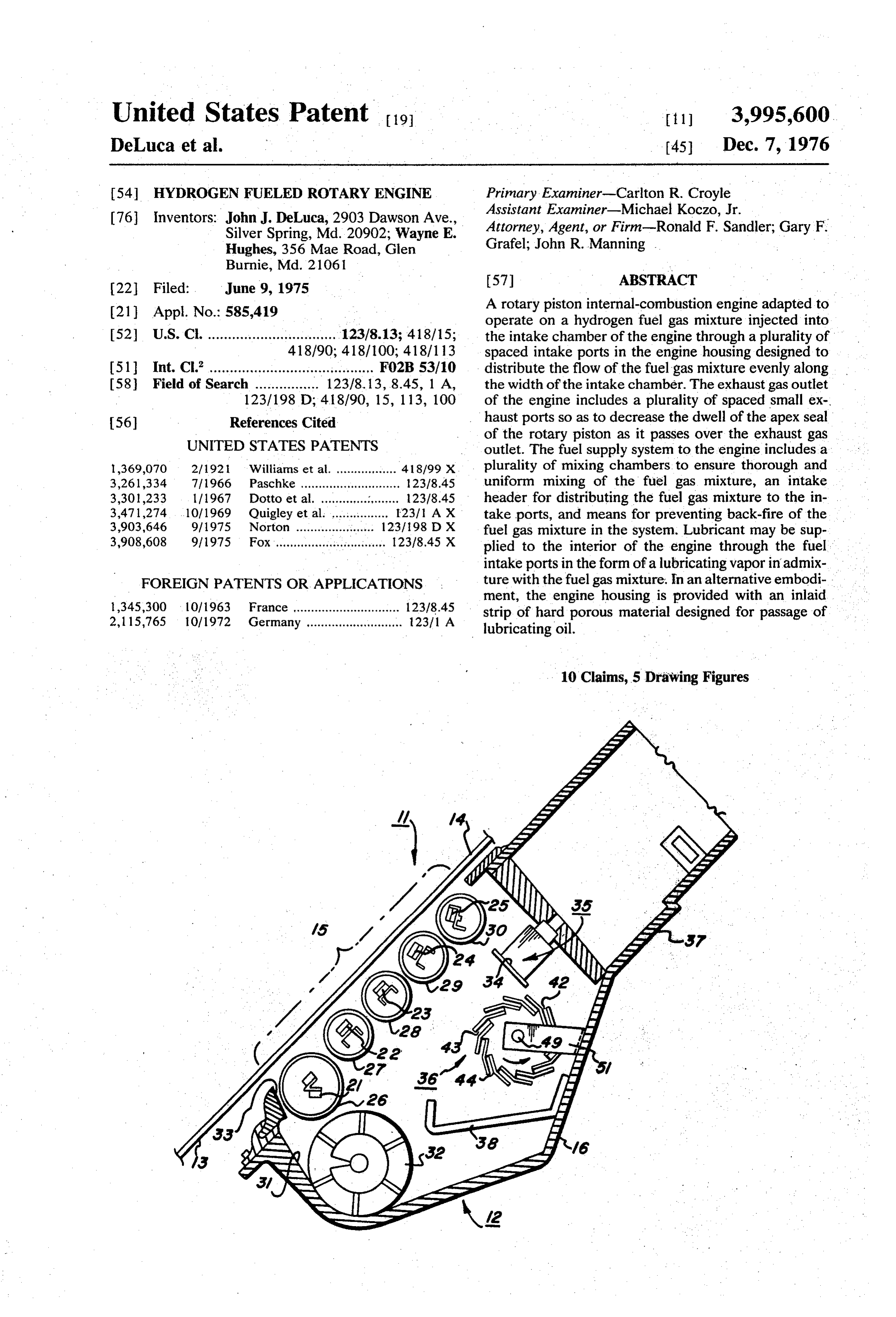
United States Patent to l 3,995,600 DeLuca et al. 45 Dec. 7, 1976 54 HYDROGEN FUELED ROTARY ENGINE Primary Examiner-Carlton R. Croyle 76 Inventors: John J. DeLuca, 2903 Dawson Ave., Assistant Examiner-Michael Koczo, Jr. Silver Spring, Md. 20902; Wayne E. Attorney, Agent, or Firm-Ronald F. Sandler; Gary F. Hughes, 356 Mae Road, Glen Grafel; John R. Manning
22 Filed: June 9, 1975 57 ABSTRACT (21) Appl. No.: 585,419 A rotary piston internal-combustion engine adapted to operate on a hydrogen fuel gas mixture injected into 52 U.S. C. ................................ 123/8.13; 418/15; the intake chamber of the engine through a plurality of 418/90; 418/100; 418/13 spaced intake ports in the engine housing designed to 51 Int. Cl. ......................................... F02B 53/10 distribute the flow of the fuel gas mixture evenly along (58) Field of Search ................ 123/8.13, 8.45, 1 A, the width of the intake chamber. The exhaust gas outlet 123/198 D; 41.8/90, 15, 113, 100 of the engine includes a plurality of spaced small ex 56) References Cited haust ports so as to decrease the dwell of the apex seal
UNITED STATES PATENTS
of the rotary piston as it passes over the exhaust gas outlet. The fuel supply system to the engine includes a l,369,070 2/192 Williams et al. ................. 41 8/99 X plurality of mixing chambers to ensure thorough and 3,261,334 7|1966 Paschke ............................ 12378.45 uniform mixing of the fuel gas mixture, an intake 3,301,233 1 11967 Dotto et al. .. . 23/8.45 header for distributing the fuel gas mixture to the in 3,471,274 . . 10/1969 Quigley et al. ................ E231. A X take ports, and means for preventing back-fire of the 3,903,646 9/1975 Norton ............. ... 1231198 DX fuel gas mixture in the system. Lubricant may be sup 3,908,608 9/1975 Fox ............................... 12318.45 X plied to the interior of the engine through the fuel intake ports in the form of a lubricating vapor in admix
FOREIGN PATENTS OR APPLICATIONS ture with the fuel gas mixture. In an alternative embodi ment, the engine housing is provided with an inlaid 1,345,300 10/1963 France .............................. 123/8.45 strip of hard porous material designed for passage of 2,115,765 10/1972 Germany ........................... 2371 A lubricating oil.
10 Claims, 5 Drawing Figures
Page 2
Drawing sheet — no readable text.
Page 3
Drawing sheet — no readable text.
Page 4
A further object of the present invention is to provide
HYDROGEN FUELED ROTARY ENGINE a hydrogen-fueled rotary piston internal-combustion engine having a fuel injection system designed to dis
ORIGIN OF THE INVENTION tribute the flow of the fuel gas mixture evenly along the The invention described herein was made by employ 5 width of the intake chamber of the engine so as to ees of the United States Government and may be man provide a smooth and even firing of the fuel gas mix ufactured and used by or for the Government for gov ture.
ernmental purposes without the payment of any royal Still another object of the present invention is to ties thereon or therefor. provide a hydrogen-fueled rotary piston internal-com O bustion engine having a fuel supply system designed to
BACKGROUND OF THE INVENTION prevent backfire of the fuel gas mixture. 1. Field of the Invention Still a further object of the present invention is to The present invention relates generally to rotary provide a hydrogen-fueled rotary piston internal-com piston internal-combustion engines, and more particu bustion engine having improved means for maintaining larly, to such engines adapted to operate on a hydrogen 15 adequate lubrication of the piston apex seal surfaces in gas fuel mixture. contact with the engine housing. 2. Brief Description of the Prior Art The foregoing and other objects are attained in ac With the growing demands in recent years of emis cordance with one aspect of the present invention sion control and cost reduction in the automobile in through the provision of a novel fuel supply and injec dustry, there has been an increased interest in the ro 20 tion system in a rotary piston internal-combustion en tary piston engine as a possible replacement for the gine which enables the engine to operate on a hydrogen conventional reciprocating piston engine. In a rotary fuel gas mixture and thereby substantially reduce the piston internal-combustion engine, a polygonal piston introduction of pollutants into the atmosphere. The rotates within an epitrochoidally-shaped engine hous fuel inlet passage ing, the piston and housing defining between them a 25 the engine housingmeans into extending through the wall of the intake chamber of the en plurality of working chambers that rotate about the axis of the housing and cyclically vary in volume as the agine comprises a plurality of intake ports spaced along line extending substantially across the width of the piston rotates relative to the housing so as to effectively engine housing transverse to the direction of rotation of provide in succession a suction space, a compression the piston so as to distribute the flow of the fuel gas space and an expansion space. The previously pro mixture evenly along the width, of the intake chamber. posed rotary piston internal-combustion engines have 30 The fuel supply system for delivering a combustible been designed to operate on conventional combustion fuel gas mixture from a fuel source to the fuel inlet fuels which are injected generally through a single in passage means of the engine includes a plurality of jection port into the working chambers of the engine mixing chambers connected in series to ensure thor where they are admixed with air for ignition. Moreover, 35 ough in the prior art rotary engines, maintaining adequate and uniform mixing of hydrogen gas with an oxi lubrication of the piston apex seal surfaces in contact dizing gas, such as air, oxygen, or water vapor, a fuel with the housing has been a major problem. intake header on the outer surface of the engine hous The detrimental air polluting effects of the exhaust ing covering all of the intake ports for distributing the gases from conventional combustion fuels are well 40 fuel gas mixture from the final mixing chamber to each known. Among the various efforts that have been made of the the intake ports, and means for preventing backfire to reduce the amount of such air pollutants, it has pre of outlet fuel gas mixture in the system. The exhaust gas passage extending through the wall of the engine viously been proposed to fuel internal-combustion en gines with hydrogen gas, which burns in air to yield ports housing also comprises a plurality of small exhaust water as the main product of combustion and therefore 45 spaced along a line extending substantially across results in fewer atmospheric contaminants. However, the width of the engine housing transverse to the direc these previous proposals of using hydrogen as a fuel for tion of rotation of the piston in order to decrease the internal-combustion engines all employed conventional dwell of the apex seal of the piston as it passes over the reciprocating piston-type internal-combustion engines exhaust gas outlet. An exhaust gas header on the outer and suffered because of the various intake and exhaust surface of the engine housing covers all of the exhaust valve problems and the extreme difficulties involved in 50 ports and terminates in a single exhaust pipe. producing a uniform explosion mixture in the firing Lubricant for lubricating the apex seal surfaces of the chamber so as to provide an even ignition and allow the rotary piston in contact with the engine housing, in a full high energy content of the fuel mixture to be uti preferred embodiment, is supplied to the interior of the lized. engine through the fuel intake ports in the form of a 55 lubricating vapor in admixture with the fuel gas mix
OBJECTS AND SUMMARY OF THE INVENTION ture, in which case there is connected to the mixing It is therefore an object of the present invention to chambers of the fuel supply system a source of lubricat provide a rotary piston internal-combustion engine ing oil provided with vaporizer means for converting designed to operate in a manner so as to substantially the lubricating oil to lubricating vapor. In an alternative reduce the introduction of pollutants into the atmo 60 embodiment, the engine housing is provided with an in sphere. laid strip of hard porous material leading to the intake Another object of the present invention is to provide chamber of the engine and designed for the passage of a rotary piston internal-combustion engine designed to lubricating oil. . . . . .. . operate on a hydrogen fuel gas mixture.
An additional object of the present invention is to 65 BRIEF DESCRIPTION OF THE DRAWINGS provide a hydrogen-fueled rotary piston internal-com Various objects, features and attendant advantages bustion engine designed to produce a uniform explo of the present invention will be more fully appreciated sion mixture in the firing chambers of the engine. as the same becomes better understood from the fol
Page 5
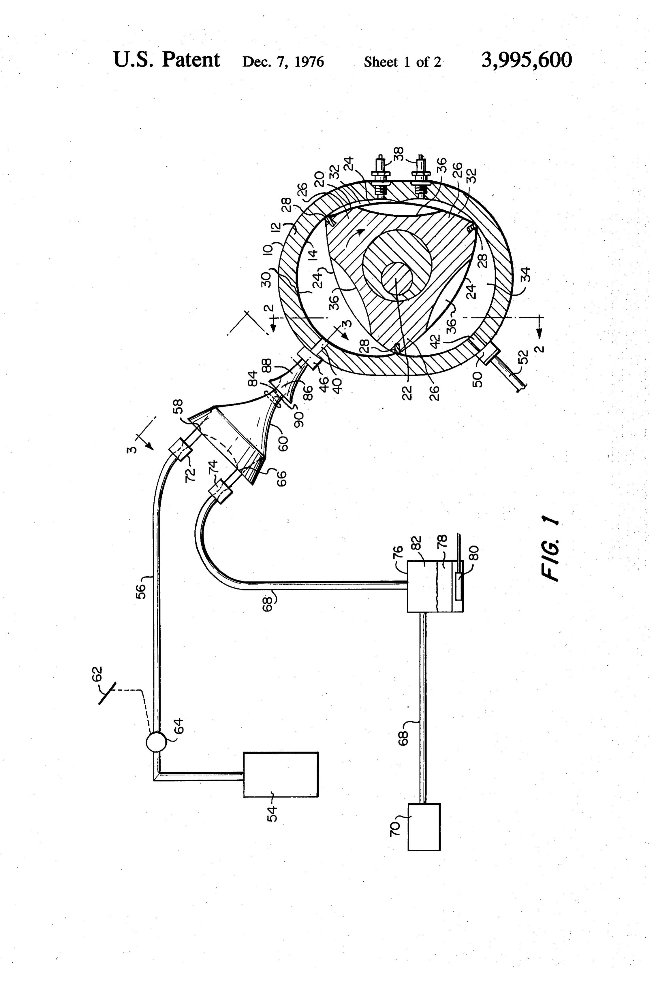
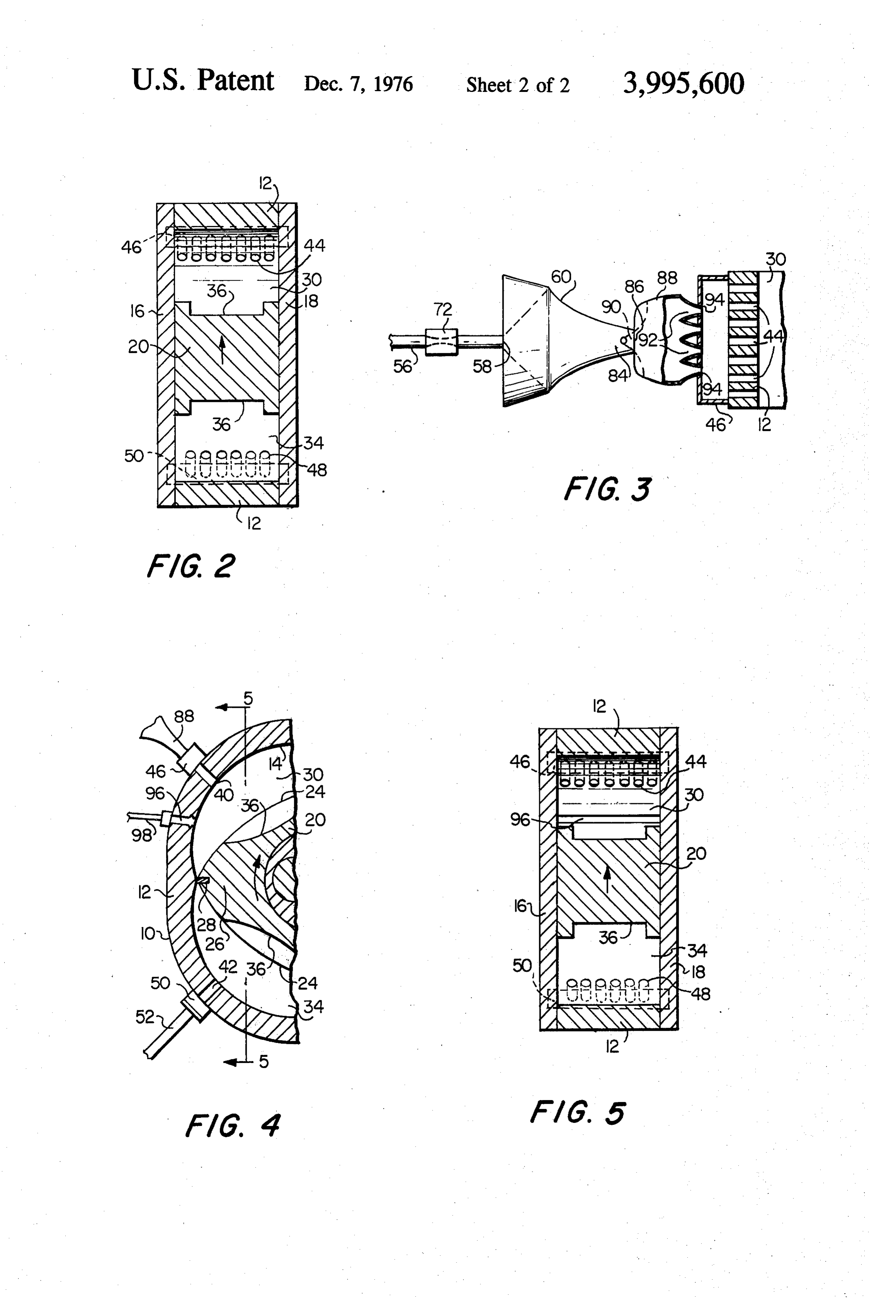
lowing detailed description of the present invention space 32, and at the appropriate time in the engine when considered in connection with the accompanying cycle, the sparkplugs 38 provide ignition for a com drawings, in which: pressed combustible gas mixture which, on expansion, FIG. 1 is a central vertical section of a rotary piston drives the rotary piston 20 in the direction of the arrow. internal-combustion engine showing the rotary piston The conventional rotary piston internal-combustion positioned within the engine housing, in combination engine thus far described is provided, in accordance with an elevational view of a preferred embodiment of with the present invention, with novel fuel inlet passage the fuel supply and injection system of the present means 40 extending through the peripheral wall 12 of invention; the engine housing 10 into the suction space 30, and FIG. 2 is a sectional view taken substantially along 10 novel exhaust gas outlet passage means 42 extending the line 2-2 of FIG. 1, looking in the direction of thethrough the peripheral wall 12 of the engine housing 10 arrows; from the expansion space 34. As best seen in FIGS. 2 FIG. 3 is a partial top view of the system shown in and 3, the fuel inlet passage means 40 comprises a FIG. 1, taken partly in section substantially along theplurality of intake ports 44 spaced along a line extend line 3-3 of FIG. 1, looking in the direction of the 15 ing substantially across the width of the peripheral wall arrows; 12 of the engine housing 10 transverse to the direction FIG. 4 is a partial elevational view, taken partly in of rotation of the rotary piston 20. The use of this con vertical section, illustrating an alternative embodiment figuration instead of the one large intake port used in employing a separate lubricating oil inlet means; and the prior art rotary engines serves the purpose of dis FIG. 5 is a sectional view taken substantially along tributing the flow of the fuel gas mixture evenly along the lines 5-5 of FIG. 4, looking in the direction of the the width of the intake chamber of the engine so as to aOWS. produce a smooth and even firing of the fuel has mix
DETAILED DESCRIPTION OF PREFERRED
ture. A hollow fuel intake header 46 extending across
EMBODIMENTS
the width of the outer surface of the peripheral wall 12 25 of the engine housing 10 covers all of the intake ports
Referring now to the drawings, and in particular to 44 for distributing the fuel gas mixture from the fuel FIGS. 1-3, a hydrogen-fueled rotary piston internal supply system to each of the intake ports. combustion engine in accordance with one embodi As best seen in FIG. 2, the exhaust gas outlet passage ment of this invention, is shown as including an engine means 42 similarly comprises a plurality of exhaust housing 10 comprising a peripheral wall 12 that has a 30 ports 48 spaced along a line extending substantially curved inner surface 14, and a pair of axially-spaced across the width of the peripheral wall 12 of the engine end walls 16 and 18 that are disposed on opposite sides housing 10 transverse to the direction of rotation of the of the peripheral wall 12 and secured thereto. The rotary piston 20. The use of this configuration instead curved inner surface 14 of the engine housing 10 has of the one large exhaust port used in the prior art rotary basically the form of an epitrochoid in geometric shape 35 engines serves the purpose of decreasing the dwell of and includes two lobe portions. the sealing members 28 on the apex portions 26 of the Within the engine housing 10, the rotary piston inter rotary piston 20 as they pass over the exhaust gas out nal-combustion engine is of conventional construction let. An exhaust gas header 50 extending across the and includes a generally triangular rotary piston 20 width of the outer surface of the peripheral wall 12 of rotatably mounted in known manner so as to rotate 40 the engine housing 10 covers all of the exhaust ports 48 relative to the engine housing 10 and eccentrically with and terminates in a single exhaust pipe 52. respect to the main engine axis 22. As shown most The line of intake ports 44 and the line of exhaust clearly in FIG. 1, the rotary piston 20 includes three ports 48 are spaced from each other across the line arcuate working faces 24 and three apex portions 26. separating the suction space 30 from the expansion The apex portions 26 carry radially movable sealing 45 space 34 by at least 90, and preferably as much as members 28 which are in substantially continuous gas 120, with respect to the main engine axis 22. In the sealing engagement with the inner surface 14 of the preferred embodiment as shown in FIG. 2, the number engine housing 10 as the rotary piston 20 rotates within of the intake ports 44 and the number of exhaust ports and relative to the engine housing 10. The three work 48 differ by 1, with the spacing of the intake ports and ing faces 24 of the rotary piston 20 cooperate with the 50 exhaust ports along their respective lines being such inner surface 14 of the engine housing 10 to effectively that the intake ports and exhaust ports are in staggered . define therebetween three separate working chambers relation to each other. If intake ports 44 and exhaust separated by the sealing members 28. As the rotary ports 48 were in line and of the same number, sealing piston 20 rotates relative to the engine housing 10, in members 28 would not wear when they pass over the the clock-wise direction indicated by the arrow as 55 intake and exhaust port openings. This will effect un viewed in FIG. 1, each of these working chambers even wear of the sealing members which will cause gaps rotates about the main engine axis 22 and cyclically to form between the sealing members and surface 14 varies in volume so as to effectively provide in succes thereby allowing the hydrogen fuel gas mixture and sion a suction space 30, a compression space 32, and an exhaust gases to escape through the gaps. The result expansion space 34. The working faces 24 of the rotary 60 would be poor compression and exhaust gas extraction. piston 20 are provided with cut-out portions or chan By staggering the intake and exhaust ports and prefer nels 36 that permit gases in the combustion space 32 to ably making the exhaust ports one less than the intake pass freely from one lobe of the epitrochoidal inner ports, all contact areas of the sealing members will surface 14 to the other lobe when the rotary piston 20 wear evenly for each revolution of the piston, thereby is in the maximum compression position shown in FIG. 65 ensuring that all contact areas of the sealing members 1. remain in sliding contact with surface 14. Although the Sparkplugs 38 are mounted in the peripheral wall 12 intake ports and exhaust ports are shown as being cir of the engine housing 10 adjacent to the compression cular in cross-section, such ports, if desired, can be
Page 6
formed in other cross-sectional shapes, such as oblong or rectangular.
When the gaseous mixture enters the suction space 30 of the engine, the lubricating vapor contained
The rotary piston internal-combustion engine of the therein condenses on the inner surface 14 of the pe present invention is designed to operate on a combusti ripheral wall 12 of the engine housing 10, and thereby ble fuel gas mixture of hydrogen with an oxidizing gas, effects lubrication on the surfaces of the sealing mem such as air or oxygen, mixed with water vapor. A uni bers 28 in contact with the engine housing as the rotary form combustible hydrogen fuel gas mixture is supplied piston 20 rotates within the engine housing. With the to the suction space 30 of the engine through the intake rotation of the rotary piston.20 within the engine hous ports 44 by means of the fuel supply system illustrated ing, the combustible hydrogen fuel gas mixture is suc in FIGS. 1 and 3 and which terminates in the fuel intake 10 cessively compressed, ignited by means of the spark header 46. The fuel supply system includes a hydrogen plugs 38, expanded, and finally exhausted through the storage tank 54 containing hydrogen gas under pres exhaust ports 48, the exhaust gas header 50 and the Sure, and a hydrogen gas conduit 56 connecting the exhaust pipe 52.
hydrogen storage tank 54 to the hydrogen gasinlet 58. The above-described fuel supply and injection system of a first mixing chamber 60. A control pedal or accel 15 in accordance with the present invention is so designed erator 62 is operatively linked to a valve 64 in the that each succeeding orifice area is larger in cross-sec hydrogen gas conduit 56 to vary the amount of hydro tion than the preceding orifice area so as to inhibit the building up in the system of any back pressure. This, gen fed into the first mixing chamber 60. The first together mixing chamber 60 is also provided with an oxidizing 20 with the one-way valve 90 disposed in the gas inlet 66, to which is connected an oxidizing gas. gaseous mixture outlet 84 of the first mixing chamber conduit 68. In the embodiment shown, with air being drogen 60 and the anti-backfire orifices 72 and 74 in the hy gas conduit 56 and the oxidizing conduit 68, used as the oxidizing gas, the other end of the oxidizing respectively, gas conduit 68 is connected to an air cleaner 70 any danger ofensure operation of the engine without backfire of the combustible fuel gas through which atmospheric air is drawn into the sys 25 tem. If pure oxygen is to be used as the oxidizing gas, mixture reaching the fuel gas sources. Moreover, the the air cleaner 70 would be replaced with an oxygen two mixing chambers, the fuel intake header and the multiple port fuel inlet passage ensure a thorough and storage tank containing oxygen gas under pressure, in uniform mixing of the fuel gases and an even distribu which case the oxidizing gas conduit 68 would be pro tion of the fuel gas mixture along the width of the in vided with suitable valving arrangement to regulate the 30 take chamber amount of oxygen fed to the first mixing chamber 60, and even firingofofthetheenginefuel so as to produce a smooth gas mixture within the en similar to that described above for the hydrogen gas. gine. - Both the hydrogen gas conduit 56 and the oxidizing gas In the embodiment of the present invention in FIGS. conduit 68 are provided with anti-backfire orifices 72 1-3 and described above, lubricant for effecting lubri and 74, respectively, adjacent to their connections with cation of the surfaces of the rotary piston apex sealing the first mixing chamber 60 for preventing backfire of 35 members the combustible fuel gas mixture from reaching the supplied to28theininteriorcontact with the engine housing, is of the engine through the fuel sources of the fuel gases. ' inlet passage 40 in the form of a lubricating vapor in Connected into the oxidizing gas conduit 68 is a lubricant supply tank 76 having its lower portion filled 40 admixture with the fuel gas mixture. In an alternative embodiment of the present invention, illustrated in with lubricating oil 78, and provided with an electric FIGS. 4 and 5, lubricant is supplied to the interior of heater 80 for vaporizing the lubricating oil 78 and the engine in the form of a lubricating oil through a thereby converting it to lubricating vapor which fills separate lubricating oil inlet passage, in which case the the upper portion 82 of the tank 76. The oxidizing gas lubricant supply tank 76 could be eliminated from the conduit 68 passes through and opens into the upper 45 fuel supply system shown in FIG. 1 so that the oxidizing portion 82 of the tank 76 and thereby carries the lubri gas conduit 68 would lead directly from the oxidizing cating vapor with the oxidizing gas into the first mixing gas source to the first mixing chamber 60. chamber 60. s ' - 'i In the embodiment shown in FIGS. 4 and 5, the en In the first mixing chamber 60, initial mixing together gine housing 10 is modified so as to include a lubricat of the hydrogen gas, the oxidizing gas and the lubricat 50 ing oil inlet passage consisting of an inlaid strip 96 of ing vapor is effected. The first mixing chamber 60 is hard porous material extending through the peripheral provided with a gaseous mixture outlet 84 which is in wall 12 thereof into the suction space 30 of the engine. communication with the gaseous mixture inlet 86 of a As shown in FIG. 5, the inlaid strip 96 extends substan second mixing chamber 88 wherein the gases are fur tially across the width of the peripheral wall 12 of the ther mixed so as to ensure a more uniform combustible 55 engine housing transverse to the direction of rotation of fuel gas mixture. The gaseous mixture outlet 84 of the the rotary piston 20. The inlaid strip 96 maybe made, first mixing chamber 60 is provided with a one-way for example, of sintered tungsten, tantalum, molybde valve 90 for preventing backflow of the gaseous mix num, or any metal or ceramic material that exhibits the ture from the second mixing chamber 88 to the first proper porosity so as to allow the passage of lubricating mixing chamber 60. As shown in FIG. 3, the second 60 oil therethrough and the properhardness so that its rate mixing chamber 88 is provided with a plurality of injec of wear is comparable to that of the surrounding hous tion nozzles 92 which project into openings 94 in the ing wall to avoid premature failure of the piston apex top of the fuel intake header 46 for injecting the gase sealing members 28 due to uneven surfaces between ous mixture from the second mixing chamber 88 into the inlaid strip and the surrounding housing wall. Lu the fuel intake header 46, which in turn distributes the 65 bricating oil from a lubricating oil supply tank, not gaseous mixture to each of the intake ports 44 extend shown, is supplied to the inlet passage through a lubri ing through the peripheral wall 12 of the engine hous cating oil conduit 98 and passes through the inlaid strip ing 10 and into the suction space 30 of the engine. 96 either by cappillary flow or under pressure supplied
Page 7
by a suitable pump, not shown, included in the lubricat and lubricating oil supply means for supplying lubricat ing oil supply system. ing oil from a source thereof to said lubricating oil inlet Obviously, numerous modifications and variations of calS.
the present invention are possible in light of the above 5. The rotary piston internal-combustion engine of teachings. It is therefore to be understood that within 5 claim 1, wherein said delivering means includes lubri the scope of the appended claims, the invention may be cating vapor supply means connected to said fuel sup practiced otherwise than as specifically described ply means for effecting of lubricating vapor with said herein. combustible fuel gas mixture for injection into the in What is claimed as new and desired to be secured by terior gas of said housing means through said hydrogen fuel mixture inlet passage means, said lubricating vapor
Letters Patent of the United States is: 10 1. A rotary piston internal-combustion engine vaporizer supply means comprising a source of lubricating oil and adapted to operate on a combustible hydrogen fuel gas lubricatingmeans vapor.
for converting said lubricating oil to mixture, comprising: engine housing means; polygonal 6. The rotary piston internal-combustion engine of piston means within said housing means rotatable rela claim tive to said housing means and cooperating therewith means1 includes 15 wherein said hydrogen fuel gas mixture supply a first mixing chamber means for ef to effectively define therebetween a plurality of work fecting initial mixing of the gases composing said com ing chambers that rotate about the axis of said housing bustible hydrogen fuel means and cyclically vary in volume as said piston chamber means having agas mixture, said first mixing hydrogen gas inlet, an oxidiz means rotates relative to said housing means so as to 20 ing gas inlet and a gaseous mixture outlet, effectively provide in succession a suction space, a conduit means for supplying hydrogen hydrogen gas compression space and an expansion space; a plurality source thereof to said hydrogen gas inlet of said firsta gas from of apex seal means connected to and circumferentially mixing chamber means; oxidizing gas conduit means spaced around the periphery of said piston means and for supplying an oxidizing gas from a source thereof to in sliding engagement with said housing means; hydro said oxidizing gas inlet of said first mixing chamber gen fuel gas mixture inlet passage means extending 25 means; and a second mixing chamber means for effect through the wall of said housing means into said suction ing further mixing of said hydrogen fuel gas mixture, space and comprising a plurality of intake ports spaced said second mixing chamber means having a gaseous along a line extending substantially across the width of mixture inlet in communication with said gaseous mix said housing means transverse to the direction of rota ture outlet of said first mixing chamber means and a tion of said piston means, hydrogen fuel gas mixture plurality of injection nozzle means for injecting said supply means for supplying said combustible hydrogen hydrogen fuel gas mixture from said second mixing fuel gas mixture from a hydrogen fuel gas mixture chamber means into said hydrogen fuel gas mixture source to said hydrogen fuel gas mixture inlet passage intake header means.
means, said hydrogen fuel gas mixture supply means 35 7. The rotary piston internal-combustion engine of terminating in hydrogen fuel gas mixture intake header claim 6, further including one-way valve means dis means on the outer surface of said housing means cov posed in said gaseous mixture outlet of said first mixing ering all of said intake ports for distributing said hydro chamber means for preventing backflow of said gase gen fuel gas mixture to each of said intake ports, ex ous mixture from said second mixing chamber means to haust gas outlet passage means extending through the said first mixing chamber means.
wall of said housing means from said expansion space 40 8. The rotary piston internal-combustion engine of comprising a plurality of exhaust ports spaced along a claim 6, further including anti-backfire orifice means line extending substantially across the width of said both in said hydrogen gas conduit means and in said housing means transverse to the direction of rotation of oxidizing gas conduit meand for preventing backfire of said piston means and the line of said exhaust ports 45 said combustible hydrogen fuel gas mixture from being staggered in relationship to the line of said intake reaching said source of hydrogen fuel gases. ports for maintaining even wear on said apex seal 9. The rotary piston internal-combustion engine of means; and means for delivering a lubricating fluid into claim 6, wherein said delivering means includes lubri said working chambers to lubricate said apex seals. cating vapor supply means in communication with said 2. The rotary piston internal-combustion engine of 50 oxidizing gas conduit means, whereby lubricating vapor claim 1 wherein said exhaust gas outlet passage means is carried with said oxidizing gas to said first mixing further includes exhaust gas header means on the outer chamber means and admixed with said combustible surface of said housing means covering all of said ex hydrogen fuel gas mixture for injection into the interior haust ports and terminating in a single exhaust pipe. of said housing means through said hydrogen fuel inlet 3. The rotary piston internal-combustion engine of passage means, said lubricating vapor supply means claim 2 wherein the line of said intake ports and the comprising a source of lubricating oil and vaporizer line of said exhaust ports are spaced from each other means for converting said lubricating oil to lubricating across the line separating said suction space from said vapor.
expansion spaced by at least 90 with respect to the 10. The rotary piston internal-combustion engine of main axis of the engine and the number of said intake 60 claim 9, wherein said lubricating vapor supply means ports and the number of said exhaust ports differ by 1. comprises a tank having a lower portion filled with 4. The rotary piston internal-combustion engine of lubricating oil and provided with heating means for claim 1, wherein said delivering means includes lubri vaporizing said lubricating oil, and an upper portion cating oil inlet means extending through the wall of said containing the vaporized lubricating oil, and said oxi housing means, into said suction space and comprising dizing gas conduit means passes through and opens into an inlaid strip of hard porous material extending sub 65 said upper portion of said tank so as to carry said lubri stantially across the width of said housing means trans cating vapor with saidk oxidizing
gas.
verse to the direction of rotation of said piston means,
Provenance
- Collection
- Cited prior art
- Original PDF
- patentimages.storage.googleapis.com →
- Filed
- 1975-06-09
- Pages
- 7
- Method
- pdftotext (the PDF's own text layer) + pdftoppm 300dpi page scans
- Source
- Google Patents bibliographic record
- Granted
- 1976-12-07
- Inventors
- John J. DeLuca; Wayne E. Hughes
- Transcribed from
- patentimages.storage.googleapis.com →