patent · US3991740
Sea shell solar collector
16 November 1976
Page 1 — bibliographic record
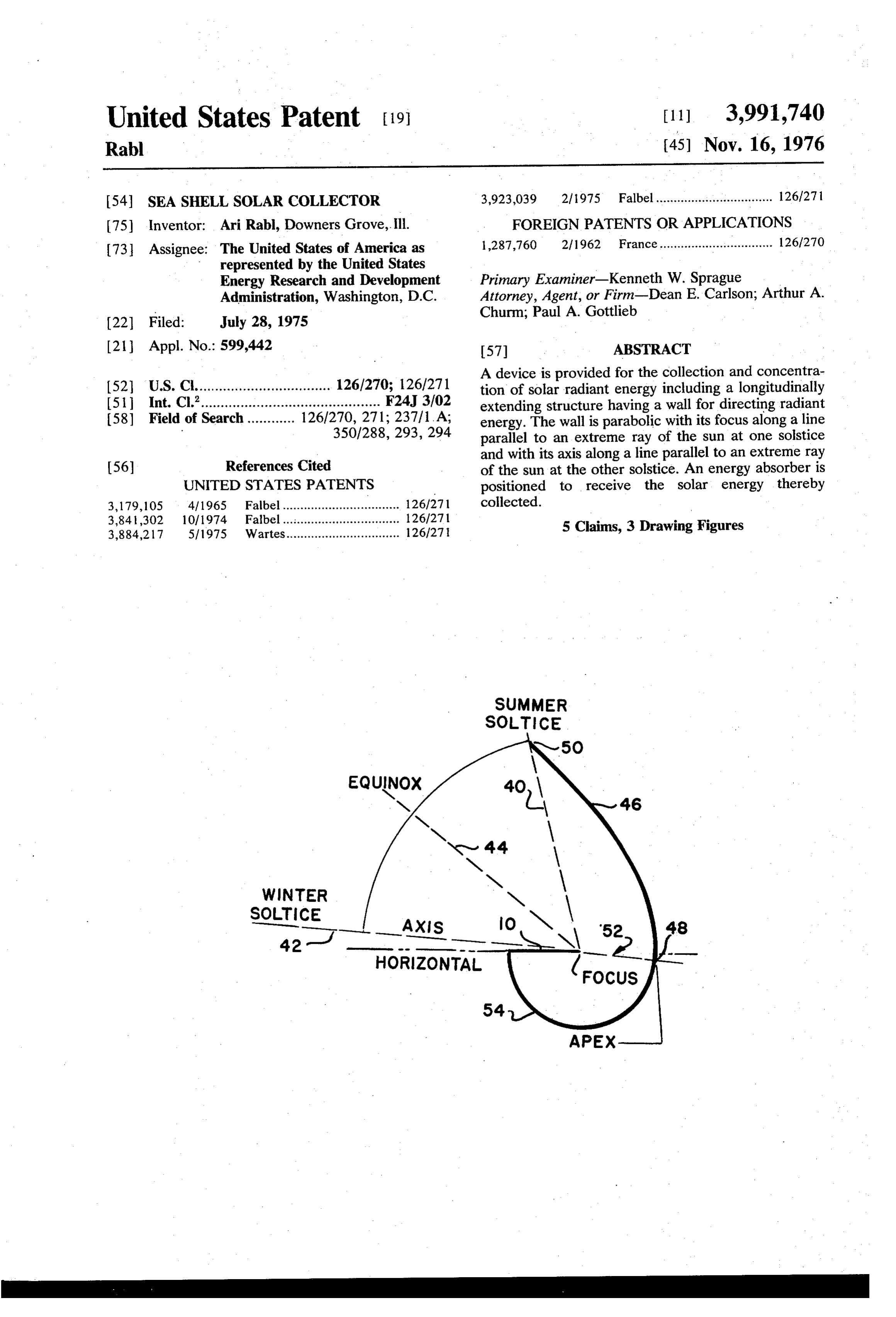
United States Patent (19) [11] 3,991,740 Rabl (45) Nov. 16, 1976 54 SEA SHELL SOLAR COLLECTOR 3,923,039 2/1975 Fallbel................................. 126/27 75) Inventor: Ari Rabl, Downers Grove, Ill. FOREIGN PATENTS OR APPLICATIONS 73 Assignee: The United States of America as 1,287,760 2/1962 France................................ 126/270 represented by the United States
Energy Research and Development Primary Examiner-Kenneth W. Sprague
Administration, Washington, D.C. Attorney, Agent, or Firm-Dean E. Carlson; Arthur A. (22) Filed: July 28, 1975 Churm; Paul A. Gottlieb (21) Appl. No.: 599,442 57 ABSTRACT A device is provided for the collection and concentra
2 126/270; 126/271 tion of solar radiant energy gy including a longitudinally 51 nt. Cl.............................................. F24 3/92 extending structure having a wall for directing radiant 58) Field of Search............ 126/270, 271; 237/1. As energy. The wall is parabolic with its focus along a line 350/288, 293,294 parallel to an extreme ray of the sun at one solstice
O and with its axis along a line parallel to an extreme ray 56) References Cited of the sun at the other solstice. An energy absorber is UNITED STATES PATENTS positioned to receive the solar energy thereby 3,179,105 4f 1965 Fabel................................. 126/271 collected.
3,841,302 10/1974 Fallbel........ - - - - - - - - - -- 126/271 O ... r. 3,884,217 5/1975 Wartes................................ 126/27 | 5 Claims, 3 Drawing Figures
Page 2
Drawing sheet — no readable text.
Page 3
ture, as will be described with reference to FIG. 3. The
SEASHELL SOLAR COLLECTOR function of the collection device is to concentrate en
CONTRACTUAL ORIGIN OF THE INVENTION
ergy from the sun onto the surface of an energy ab sorber 10. The energy absorber may be for example, a
The invention described herein was made in the pipe containing fluid, a photovoltaic cell, or any other course of, or under, a contract with the UNITED type of energy receiver responsive to radiant energy. STATES ENERGY RESEARCH AND DEVELOP The present disclosure relates to developing a collec MENT ADMINISTRATION. tor having a concentrating side wall for reflecting en ergy incident thereon onto the energy absorber 10. In
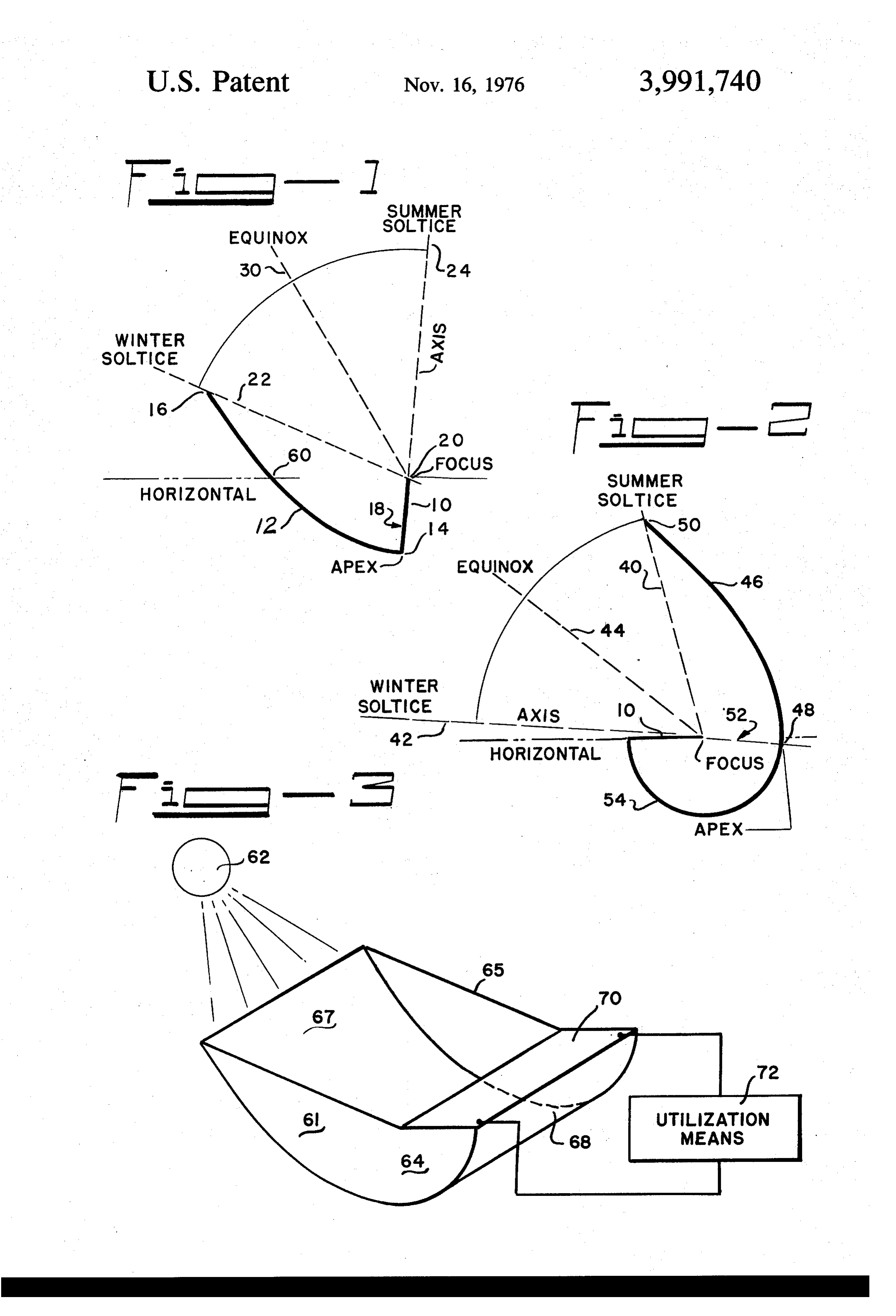
BACKGROUND OF THE INVENTION 10 particular, the concentration factor of the collector, The present invention relates generally to the collec which is defined as the width of the entrance aperture tion of radiant energy from solar sources. A particular divided by the width of the exit aperture, is to be sea type of solar collector is the cylindrical collector, which sonably variable, with either peak concentration in is formed by extending a transverse cross section longi 15 summer or peak concentration in winter, as desired. tudinally to form a trough-like structure, examples of Referring to FIG. 1 there is shown a collector with peak which are described in a publication, Solar Energy, Vol. concentration in summer. The collector includes a 16, No. 2, pages 89–85 (1974). Prior art cylindrical concentrating wall 12 which extends between points 14 collectors generally possess uniform concentration for and 16. Concentrating wall 12 directs energy incident all angles of incidence of radiant energy. For heating thereon within particular angles, depending upon the and cooling applications, however, the load varies with 20 time of year, out exit aperture 18. Wall 12 is parabolic the seasons, e.g. heating in winter and cooling in the in contour with its axis 24 parallel to an extreme ray of summer. A solar collector with seasonably variable the sun at summer solstice. The wall extends between concentration would be advantageous if of simpler point 14 which is at the apex of the parabola and point design than the collectors of uniform output now 25 16 which is at the juncture of wall 12 and a line 22 known. parallel to an extreme ray of the sun at the winter sol It is therefore an object of this invention to provide a stice. The angular difference between lines 22 and 24 is device for collecting and concentrating solar radiation. about 72't 36 on either side of the line 30 parallel to Another object of this invention is to provide a non a ray of the sun at equinox. This angular difference is imaging solar energy collection device with seasonably 30 generally constant regardless of location, however the variable concentration. angle between the equinox position, line 30, and the SUMMARY OF THE INVENTION horizontal, parallel to the earth's surface, varies de pending upon latitude. An extreme ray of the sun is one
A solar radiation collection device is provided having which is at the largest angle with respect to a ray of the a seasonably, variable concentration. The device in 35 sun at equinox, i.e., line 30, that a ray of the sun will cludes a first side wall for directing incident radiant make. This will occur twice on each solstice, in the energy. The first wall has a transverse cross section in morning and in the evening, when the same extreme the form of a parabola having its focus along a first line angle with respect to equinox line 30 will be made by parallel to an extreme ray of the sun at one solstice and the extreme ray from the sun. The references to sol its axis parallel to an extreme ray of the sun at the other stices and equinox are based on solar time, i.e., the solstice. The parabola extends from a first point along 40 actual equinox for a particular location. the axis to no further than intersection with the first The parabolic shape of reflecting wall 12, as herein line. An energy absorber is so positioned to receive described, will have a variable concentration with re energy crossing an exit aperture between the first point spect to energy exiting exit aperture 18. The concentra and the focus. Convection loss from the absorber is tion factor is a measure of the ratio between the width 45 of the entrance aperture and the width of the exit aper limited by horizontal orientation of the absorber which is achieved by use of a second wall of circular cross ture. The exit aperture out which energy is directed by . section for directing radiant energy exiting the exit wall 12 is between point 14, the apex of the parabola aperture onto the absorber whose surface is directed and focus 20 of the parabola which lies along the apex downward. axis. The actual distance between points 20 and 16 is a 50 matter of choice since all parabolas are concentric as
BRIEF DESCRIPTION OF THE DRAWINGS all circles are concentric, differing only in size. Ab FIG. 1 shows a cross section of the solar collector for sorber 10 is positioned to extend from focus 20 to point maximal summer output; 14. The entrance aperture is the opening of the collec FIG. 2 shows a cross section of the solar collector for tor within which rays of the sun are concentrated by the maximal winter output; and 55 collector. In FIG. 1, as the sun moves from summer FIG. 3 shows the longitudinally extended structure of solstice to winter solstice, the entrance aperture de this invention. creases, being Zero at winter solstice. As the sun moves from winter solstice to summer solstice the entrance
DETAILED DESCRIPTION OF THE PREFERRED aperture increases. The increase or decrease varies EMBODIMENT with the cosine of the angle of an axis through the Referring to FIG. 1 and FIG. 2, there is shown a entrance aperture and the position of the sun. Thus the transverse cross section of two embodiments of the concentration factor varies from zero in winter to 3.4 in cylindrical solar energy concentration and collection summer without inclusion of the cosine factor which device of this invention. As the disclosed device is a will depend on the latitude. Such a variable concentra cylindrical collector, the physical structure of the col 65 tion would be ideal to drive absorption air conditioners lector is formed by extending the cross sections shown with a minimum of equipment. Note that during any in FIG. 1 and FIG. 2 along an axis perpendicular to the particular time of year the area of absorber 10 to which plane of the cross section to form a trough-like struc energy is directed by the collection device varies. At
Page 4
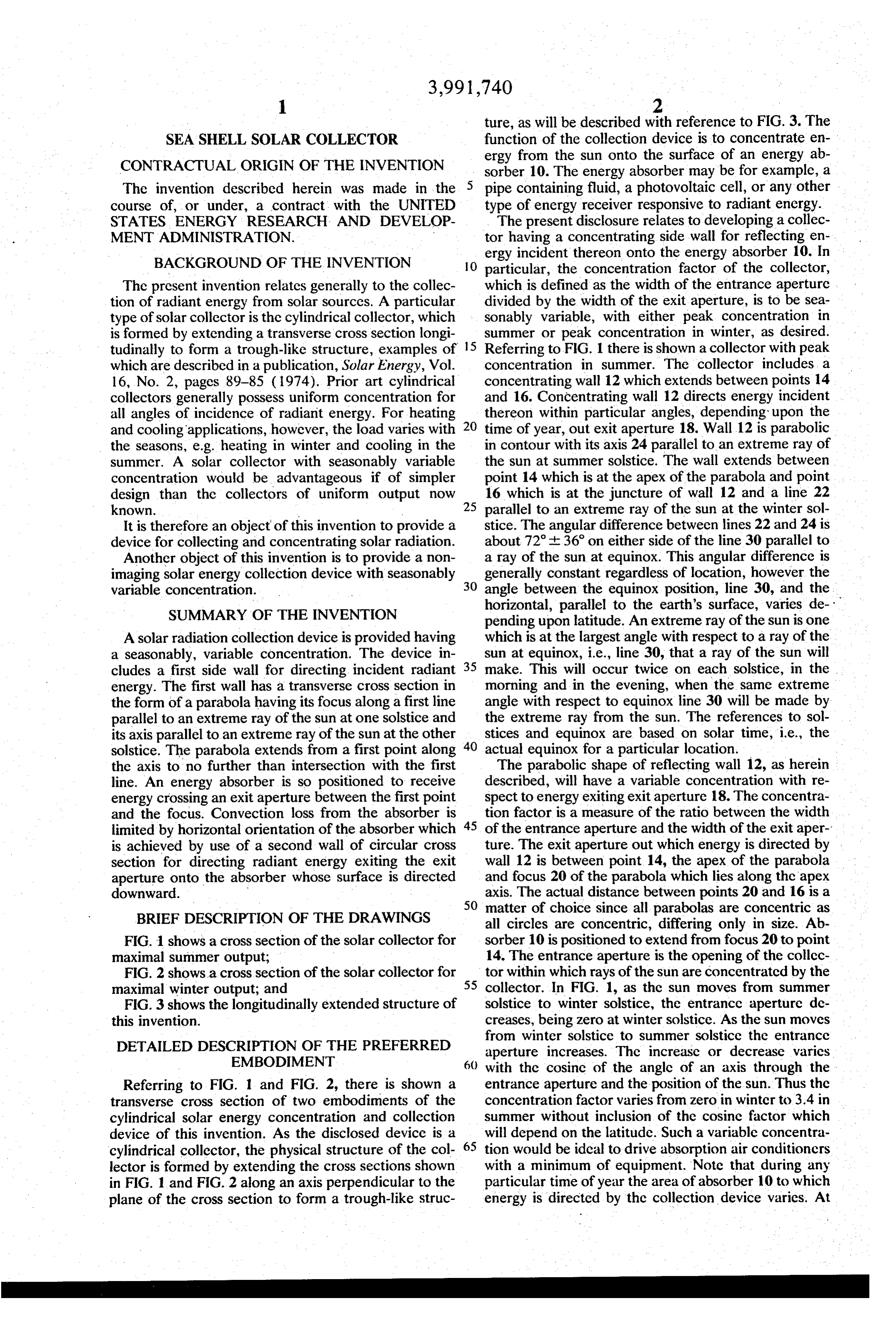
the extreme conditions, at solstices, the energy is con FIG. 1 or FIG. 2, and side walls 64 and 65 have a reflec centrated on either end of absorber 10, while around tive material thereon which reflects substantially all of equinox the energy is more equitably distributed. the solar energy incident thereon from the sun 62, as Referring to FIG. 2, there is shown a collector having for example, aluminum or silver. The reflected energy a variable concentration with peak concentration in is directed by additional circular wall 68 onto down winter. The summer solstice line 40, winter solstice line ward facing absorber 70. Connections are provided to 42 and equinox line 44 are as described in FIG. 1 for absorber 70 to allow utilization of the energy absorbed lines 24, 22 and 30, respectively. However, in FIG. 2, by absorber 70 by utilization means 72. the parabolic concentrating wall 46, which concen O The embodiments of the invention in which an exclu trates energy incident on the entrance aperture out the sive property or privilege is claimed are defined as exit aperture, has its axis along the winter solstice line follows:
42. The parabolic wall 46 extends from its apex point 1. A stationary nonimaging cylindrical solar radiation 48 along line 42, at point 48 and extends to line 40 at concentration device, having a seasonably variable point 50. In this instance, the maximum output at exit 15 concentration factor comprising:
aperture 52 between the focus on apex 42 and apex a reflective side wall for directing radiant energy with point 48 occurs at winter when the concentration fac a transverse cross section in the form of a parabola tor is about 3.4 and minimum output is at summer whose axis is a first line parallel to an extreme ray when the concentration factor is about O without inclu of the sun at one of the solstices, said parabola sion of the cosine factor. extending from the apex of said parabola along said The energy concentrated by the collectors shown in 20 first line to a second line parallel to an extreme ray FIG. 1 and FIG. 2 is directed onto energy absorber 10. of the sun at the other solstice, and an energy ab In FIG. 1 the energy absorber is shown positioned at sorber positioned to receive solar energy crossing and along exit aperture 18. In FIG. 2, the absorber is an exit aperture whose transverse cross section is positioned with the surface of the absorber upon which 25 defined by a third line from the focus of said parab energy is directed facing downward to minimize radia ola to said apex of said parabola, said energy ab tion loss which might otherwise occur if positioned at sorber and said side wall extending parallel to a exit aperture 52. This is accomplished by providing an reference axis perpendicular to the transverse cross additional wall 54 for directing, without concentration section of said side wall to form a trough-shaped or dispersion, energy exiting exit aperture 52 onto ab 30 Structure.
sorber 10. Wall 54 is circular having its center point at 2. The device of claim 1 wherein said first line is point 52 and being of radius equal to the width of the parallel to an extreme ray of the sun at winter solstice exit aperture 52. The circular wall and the downward and said second line is parallel to an extreme ray of the facing absorber may of course be used in the embodi sun at summer solstice thereby giving the device maxi ment shown in FIG. 1. 35 mal concentration in winter.
The seasonably variable nature of the concentration 3. The device of claim 1 wherein said first line is factor can be further changed by truncating the con parallel to an extreme ray of the sun at summer solstice centrating walls 12 and 46. For example, in FIG. 1, with and said second line is parallel to an extreme ray of the truncation at point 60 along line 24, which is along the sun at winter solstice thereby giving the device maximal horizontal which intersects focus point 20, the concen 40 concentration in winter.
tration ranges from .7 to 1.7, with a mean value of 1.5 4. The device of claim 1 further including a circular at equinox without inclusion of the cosine factor. Trun reflective wall for directing energy exiting said exit cation or shortening of the concentration walls 12 and aperture onto said absorber having a circular trans 54, presents a wider entrance aperture for some rays, verse cross section whose center is at said focus and such as at winter solstice in FIG. 1 and a shorter en 45 whose radius is equal in length to said third line, said trance aperture for other rays, such as its summer sol circular cross section extends from said apex, is posi stice in F.G. 1. tioned on the opposite side of said third line from said An example of the practical application of the princi side wall, said absorber being positioned along a second ples herein, disclosed is shown in FIG. 3. Here one radius of said circular reflective wall such that the sur embodiment of collector 61 is shown concentrating face of said absorber upon which energy is directed energy from the sun 62. Collector 61 has a transverse faces downward toward the earth's surface thereby cross section which is extended along an axis perpen reducing convective heat loss therefrom. dicular to the cross section to form a trough-like cylin 5. The device of claim 1 wherein the cross section of drical collector. Flat reflective end wall 64 and 65 fully said absorber extends along said third line from said enclose the collector 61. Concentrating wall 67 whose 55 apex to said focus. ck ck ck ck contour is generated as described with reference to
Provenance
- Collection
- Cited prior art
- Original PDF
- patentimages.storage.googleapis.com →
- Filed
- 1975-07-28
- Pages
- 4
- Method
- pdftotext (the PDF's own text layer) + pdftoppm 300dpi page scans
- Source
- Google Patents bibliographic record
- Granted
- 1976-11-16
- Inventors
- Ari Rabl; Energy Research and Development Administration ERDA
- Transcribed from
- patentimages.storage.googleapis.com →