patent · US5738766
Device for neutralizing and preventing formation of scale and method
14 April 1998
Page 1 — bibliographic record
United States Patent (19) 11 Patent Number: 5,738,766 Jefferson 45 Date of Patent: Apr. 14, 1998 54 DEVICE FOR NEUTRALIZING AND 5,368,705 11/1994 Cassidy ................................... 204f136 PREVENTING FORMATION OF SCALE AND 5,374,351 12/1994 Bolton et al. 210/9 METHOD 5,378,362 1/1995 Schoepe ...... ... 210/222 5,380,430 1/1995 Overton et al. ... 210/222 75 Inventor: George Nathan Jefferson, Gettysburg, 5,393,421 2/1995 Ohe et al. .... ... 20/223 Pa. 5,411,143 5/1995 Greene ........ ... 210/222 5,453,188 9/1995 Florescu et al. . ... 210/222 5,454,943 10/1995 Ashton et al. ... ... 20/222 73 Assignee: Nathan Jefferson Enterprises, Inc., 5,460,702 10/1995 Birkbeck et al. ... 204/149 Gettysburg, Pa. 5,460,718 10/1995 Wecket al. ......... ... 21.0/205 5,468,378 11/1995 de la Torre Barreiro ... 20/192 21 Appl. No.: 649,173 5,470,466 11/1995 Schaaf..................... ... 20/222 5,480,557 1/1996 Kawasaki et al. ...................... 210/695 22 Filed; May 17, 1996 OTHER PUBLICATIONS
52 U.S. Cl. ......................... 204/155: 210/94; 21.0/96.1: Genesis International Trading Ltd., “The Principles of Scale 210/97: 210/143: 210/222; 210,243; 204/554 Formation and Prevention", (no date provided).
(58 Field of Search ..................................... 204/155,554; Scale Watcher, Sales brochure, pp. 1-4, (no date provided). 210/94, 96.1, 97,143, 222, 243 Scale Watcher “Scale Watcher Industrial", 1976, pp. 1-4, (no month).
56 References Cited Genesis International Trading Ltd., “Electronic Scale Elimi
4,326,954 4/1982 Shroyer ................................... 210/222 Primary Examiner-Arun S. Phasge 4,938,875 7/1990 Niessen ... ... 20/695 Attorney, Agent, or Firm Thomas Hooker. P.C. 4,999,106 3/1991 Schindler ..... ... 210/222 57 ABSTRACT 5,024,759 6/1991 McGrath et al. ... 210/222 5,051,177 9/1991 Dauchez .............. ... 20/222 A descaling device for neutralizing and preventing forma 5,074,998 12/1991. De Baat Doelman .................... 20/97 tion of calcium carbonate or other scale in a water conduit 5,18,416 6/1992 Janczak et al. ...... 210/222 5,171.431 12/1992 Schutle...................................... 210/94 includes an electromagnetic coil adjacent the conduit and a 5,200,071 4/1993 Spiegel. ... 210/222 power supply for the coil. The power supply generates a 5,238,558 8/1993 Curtis ....... ... 210/222 complex triangular waveform output signal that varies con 5,238,577 8/1993 Newsom . ... 210/695 tinuously in frequency and amplitude. The output is applied 5,269,915 12/1993 Clair.... ... 210/222 across the ends of the coil creating time varying magnetic 5,271,834 12/1993 Mondiny . ... 210/222 and electric fields. The fields physically interact with mol 5,304,302 4/1994 Bossert ................ ... 210/222 ecules in waterflowing in the conduit to neutralize existing 5,356,534 10/1994 Zimmerman et al. ... 210/222 scale and prevent formation of new scale. 5,364,536 11/1994 Mercier ............... ... 210,695 5,366,623 11/1994 Clair ........ ... 210/222 5,366,630 11/1994 Chevallet ................................ 210/645 18 Claims, 5 Drawing Sheets
REGUAOR
WAWEFOR
ERNA BOCK
Page 2
Drawing sheet — no readable text.
Page 3
Drawing sheet — no readable text.
Page 4
Drawing sheet — no readable text.
Page 5
Drawing sheet — no readable text.
Page 6
Drawing sheet — no readable text.
Page 7
DEVICE FOR NEUTRALIZING AND added later, more chemicals must be added to the system. PREVENTENG FORMATION OF SCALE AND This is expensive and time consuming. Once added, chemi METHOD cals are not easily removed.
The devices that use permanent magnets can only treat the water with limited effectiveness because the electromagnetic
FIELD OF THE INVENTION fields have set directions and the water is only treated when The invention relates to a device and method for neutral it moves through the field. The prior art electromagnetic izing and preventing formation of calcium-hydrogen car devices only treat the water during the change in direction bonate scale in water flowing through a conduit, and strength of the fields and are not efficient in treating 10 different size molecules likely to form scale.
DESCRIPTION OF THE PRIOR ART
SUMMARY OF THE INVENTION
It is common for water carrying conduits to become The invention is a descaling device and method useful on clogged by calcium-hydrogen carbonate scale adhering to water conduit systems to neutralize and prevent the forma the inner wall of the conduit. The clogging causes a reduc 15 tion of scales. The device includes an electromagnetic coil tion in the flow rate and requires increased pressure to adjacent the water conduit and a specialized power supply maintain the water flow. The loss in efficiency increases the for the coil.
cost associated with operating systems using water conduits.
Several chemical approaches have been offered to prevent signalThe power supply produces a triangular wave current having variable amplitude and frequency. This signal scaling in water systems. One approach uses an ion exchang is applied ing mechanism to create neutral molecules that will not a correspondingto the ends of the coil to energize the coil and form variable electromagnetic field in the water adhere to the insides of the conduits. This approach works by flowing in the conduit.
adding sodium chloride (NaCl) to the water system. The frequency and amplitudeThe field varies with changes in sodium chloride chemically interacts with the calcium 25 changes strength in responseoftothe power signal. The field changes in the signal ampli hydrogen carbonate scale and forms neutral molecules that tude and changes direction in response direction change of are carried in solution until they can be flushed out at a later the current flow. The interaction of the fields with the Water point.
Another approach uses a chemical to prevent calcium provides an effective method of treating the water to neu hydrogen carbonate crystals from forming in the water. This tralize and prevent formation of calcium-hydrogen carbon ate Scales.
approach functions by adding phosphates to the water. The Once installed, the device continuously treats the water phosphates interact with the molecules in the water to create flowing past the coil without the need for additional parts or an environment where calcium-hydrogen carbonate forma attention. The device has a long useful life. tion is prevented.
The field generated by a variable frequency and amplitude
Further approaches use electromagnetic fields to interact 35 triangular with the calcium and bicarbonate molecules in the water. wave current signal changes direction and The electromagnetic fields agitate ionized calcium and strength at varying rates. This field effectively agitates bicarbonate molecules and cause the formulation of neutral different size molecules likely to form scale to break bonds calcium carbonate molecules that do not precipitate as scale between the molecules and water and prevent scale forma on the conduits. As the ionized calcium and biocarbonate 40 tion. The variations in field strength increase the effective molecules travel through a changing electromagnetic field, ness in treating different size molecules. The use of a the charges on the molecules interact with the field and move triangular wave input current signal agitates ionized mol ecules continuously with a field direction reversal once each the molecules toward alignment with the field. Alternating cycle.
or switching directions of the field rotates the molecules toward alignment with the changing field. This rotation for 45 Other objects and features of the invention will become alignment agitates the molecules and breaks the bonds apparent as the description proceeds, especially when taken between the molecules and bonded water molecules. With in conjunction with the accompanying drawings illustrating these bonds broken, the calcium and biocarbonate molecules the invention, of which there are four sheets and one are free to bond together to form a crystal which does not embodiment.
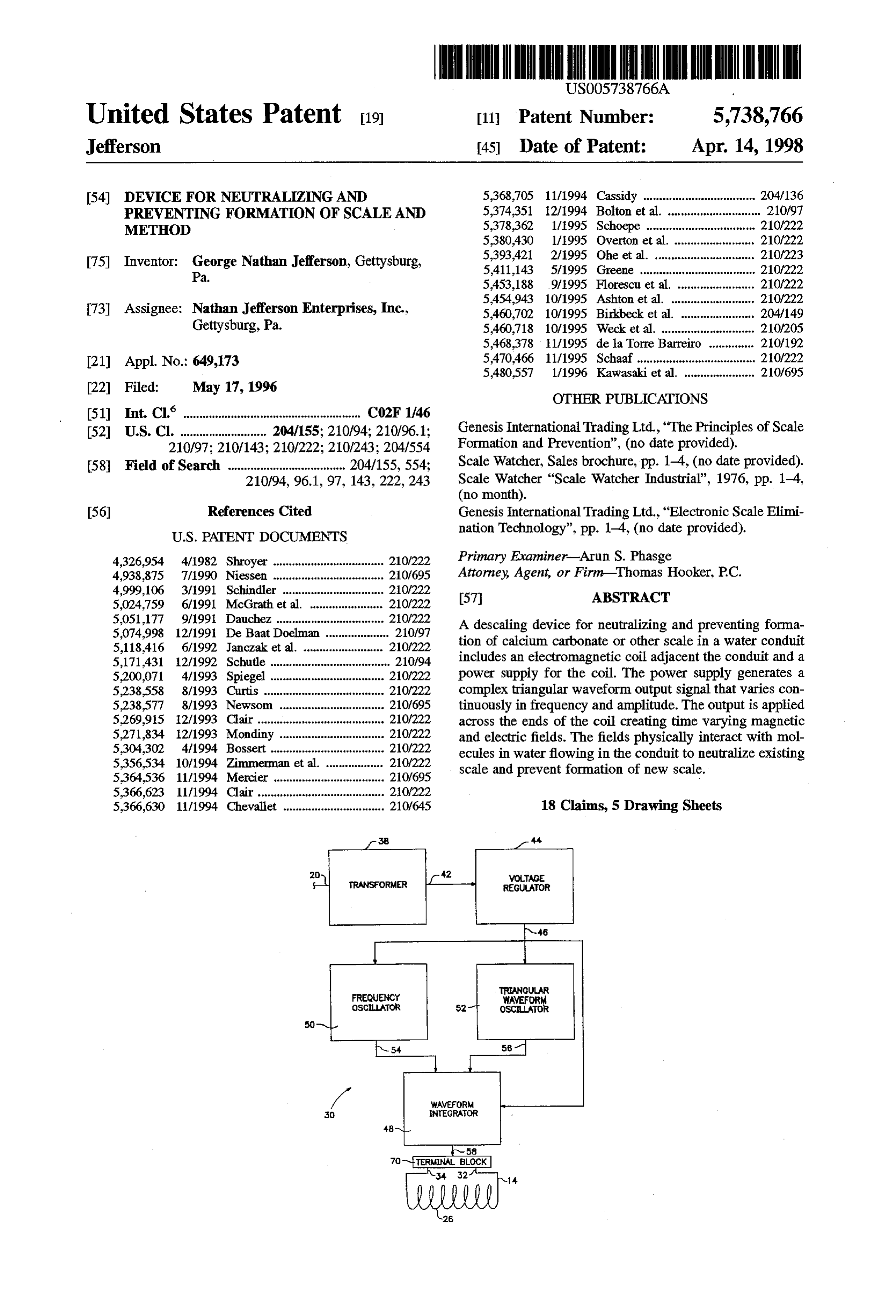
form scale. Conventional of electromagnetic fields used to 50 BRIEF DESCRIPTION OF THE DRAWINGS prevent scale are generated by aligned permanent magnets or electromagnetic coils. FIG. 1 is a view of the device according to the invention The use of permanent magnets creates electromagnetic with a coil surrounding a water conduit;
fields that have a set strength and direction. The ions move FIG. 2 is a view of an electromagnetic coil adjacent a through the constant field and are agitated by change in 55 water conduit;
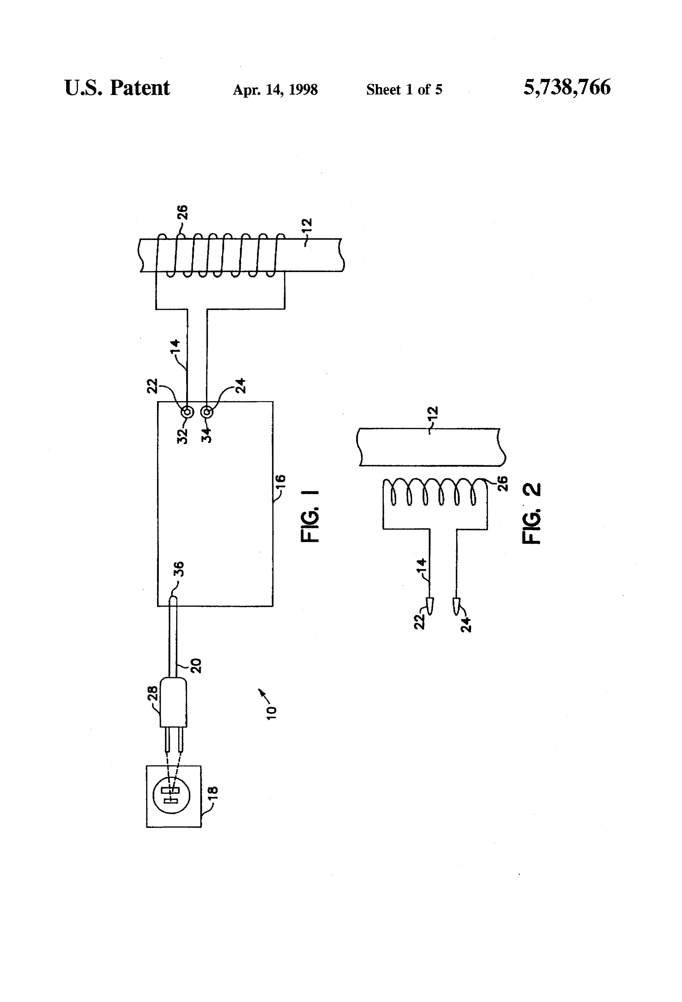
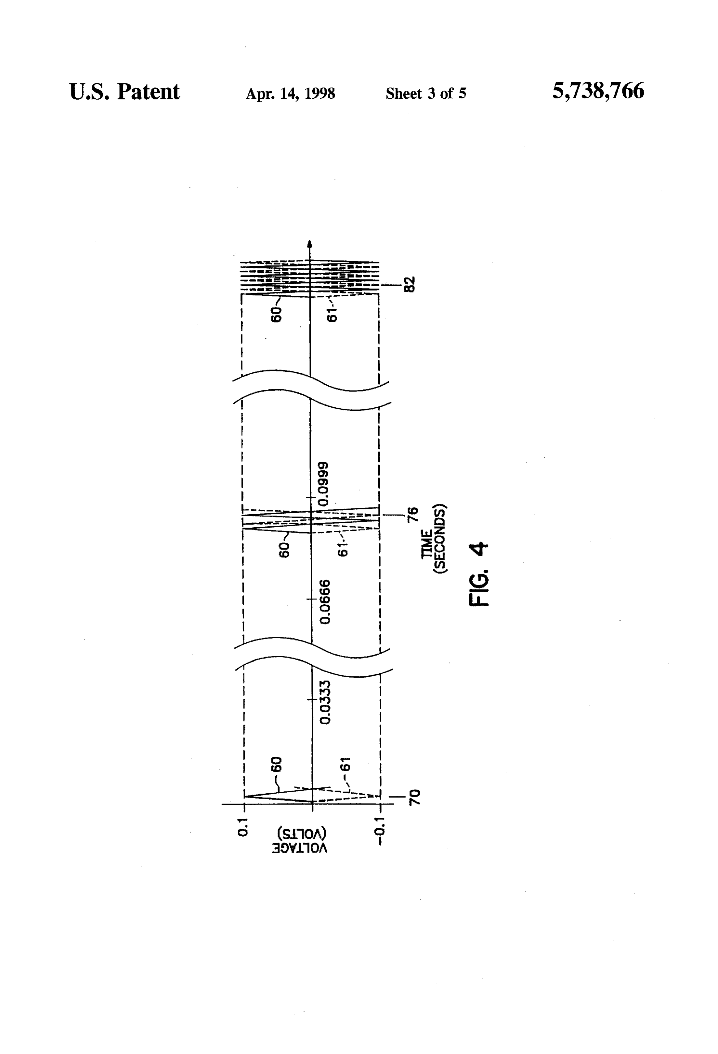
direction of the field at different locations. Electromagnets FIG. 3 is a block circuit diagram of the power supply for create pulsating electromagnetic fields. These fields treat the the device; and water during the change in direction and strength of the fields applied as the water flows through the field. FIGS. 4-7 are graphs of output signals of the power supply
These methods have significant drawbacks. In order to waveform from a variable frequency oscillator, a triangular treat the water chemically, direct access to the water is oscillator and a waveform integrator. required. Depending on the system to be treated, direct DESCRIPTION OF THE PREFERRED access is not always easy or feasible. Addition of chemicals EMBODEMENT can also limit the use of the water being treated. It is generally recognized that treatment of drinking water with 65 As illustrated in FIG. 1. descaling device 10 for neutral chemicals is not desirable. The addition of chemicals treats izing and preventing formation of scale in water flowing a certain volume of water. In order to treat water that is through a conduit 12 includes an electromagnetic coil 14
Page 8
surrounding water conduit 12, a power supply 16 having Alternatively, signals 60-63 may be truncated triangular output terminals connected to the ends of coil 14, a source waveforms and output signal 64 may be a truncated trian of electrical power 18, which can be a conventional 120 gular waveform continuously varying in frequency accord VAC source, and a power cord 20 connected between source ing to signals 60 and 61 with a varying peak amplitude 18 and power supply 16. Coil 14 includes two male con defined by signals 62 and 63. The output signal 64 would nectors 22 and 24 each connected to an end of coil 14 and have a steep linear slope to the positive or negative peak a plurality of helical loops 26 surrounding conduit 12. Plug amplitude and then have a slope of zero for a period of time 28 on cord 20 engages source 18. before rising or falling to the next peak amplitude. Power supply 16 includes a circuit 30, two female output Signals 60 and 61 may be varied in frequency from 1 Hz connectors 32 and 34 and a cord connector 36. Male to 1 MHz. Test results have shown the optimum results are connectors 22 and 24 are inserted into female connectors 32 and respectively. obtained when signals 60 and 61 (and thus output signal 64) The power supply circuit 30 includes a transformer 38 varied vary between 2 kHz and 10 kHz. Signals 62 and 63 may be connected to the cord 20 and receives 120 volt sinusoidal between 50 mA and 200A. Large commercial appli voltage signal from source 18. Transformer 38 transforms 15 iscations varied generally produce best results when the output signal between 50 mA and 10 A while residential appli the voltage signal to a 12 volt sinusoidal output signal at cations yield output 42 which is connected to voltage regulator 44. and 500 mA.optimum Amplitudes results when varied between 50 mA of 200 A have been used effec
Regulator 44 rectifies signal 42 to form a 12 volt DC regulated signal at output 46 which is connected to wave tively on commercial applications.
form integrator 48, frequency oscillator 50 and a triangular 20 Coil 14 is preferably wound from insulated number Waveform oscillator 52. fourteen AWG wire and connectors 22.24 and 32.34 are Frequency oscillator 50 generates frequency output sig preferably conventional banana plug connectors. Connec nals 60 and 61 at output 54. Waveform oscillator 52 gener tors 22 and 24 are preferably crimped on the ends of coil 14 ates amplitude output signals 62 and 63 at output 56. and connectors 32 and 34 are preferably fastened to power Integrator 48 integrates signals 60, 61, 62 and 63 to generate 25 supply 16.
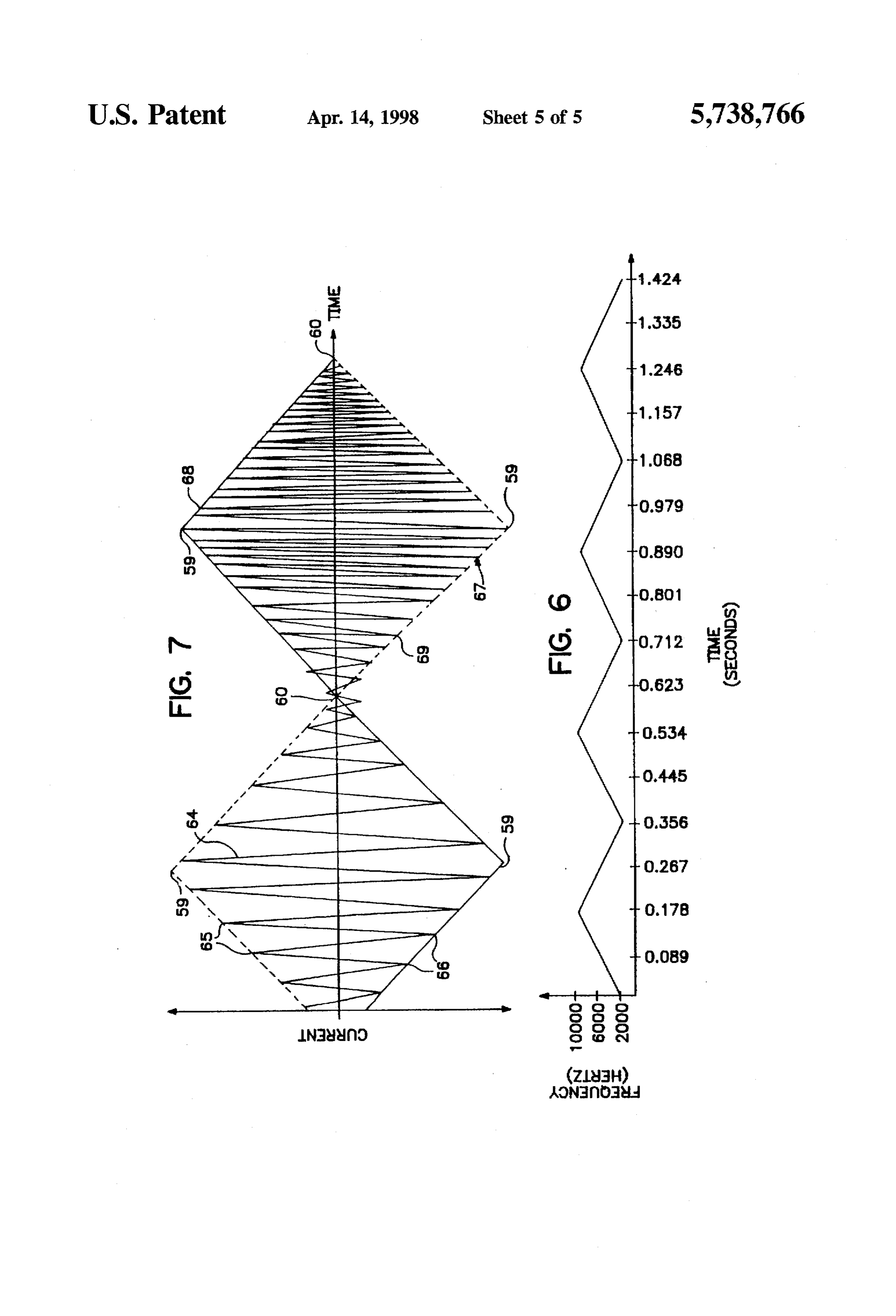
a current signal 64 at output 58. As shown in FIG.2, coil loops 26 may be located adjacent Circuit 30 also includes a terminal block 70 connected conduit 12 as opposed to around the conduit. Loops 26 must between integrator 48 and coil female connectors 32 and 34. be locatedby within a distance to conduit 12 such that the field Terminal block 70 applies circuit output signal 64 to coil 14. produced device 10 intersects water flowing in conduit As shown in FIGS. 4 and 6, frequency signals 60 and 61 30 12.
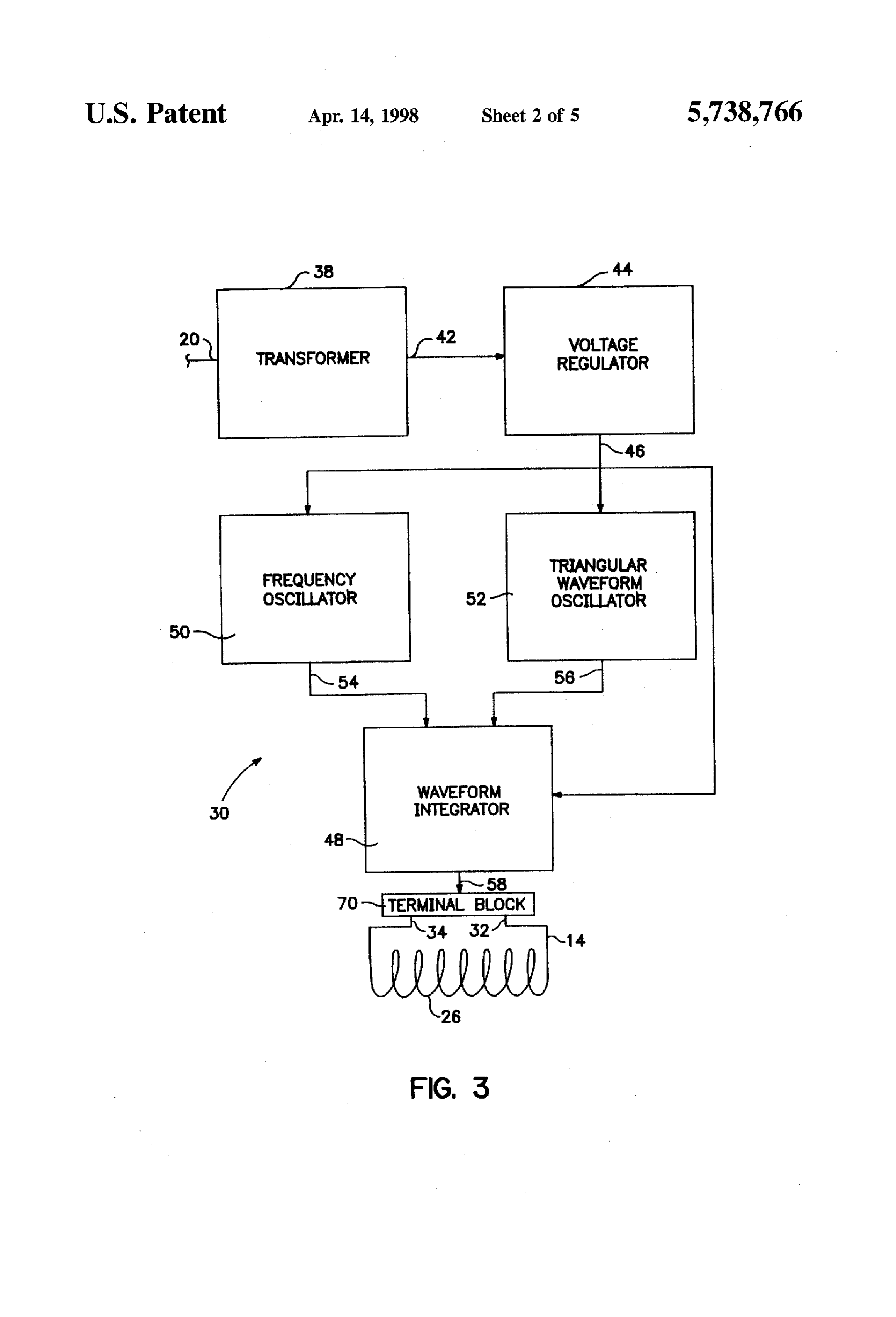
are composed of continuous triangular waveforms that oscil Coil 14 is wound around water conduit 12 in helical loops lator 50 continuously varies in frequency from 2 kHz to 10 26. For each 0.25 inches of diameter of non-ferris conduit kHz and back to 2 kHz every 0.356 seconds or at afrequency 12, five loops 26 are formed in coil 14. If conduit 12 is of of about 2.8 cycles per second. Signal 61 leads signal 60 by a ferris material, an additional 1.25 loops are formed for % cycle so that signal 61 appears as an inversion of signal 35 every 0.25 inches of diameter.
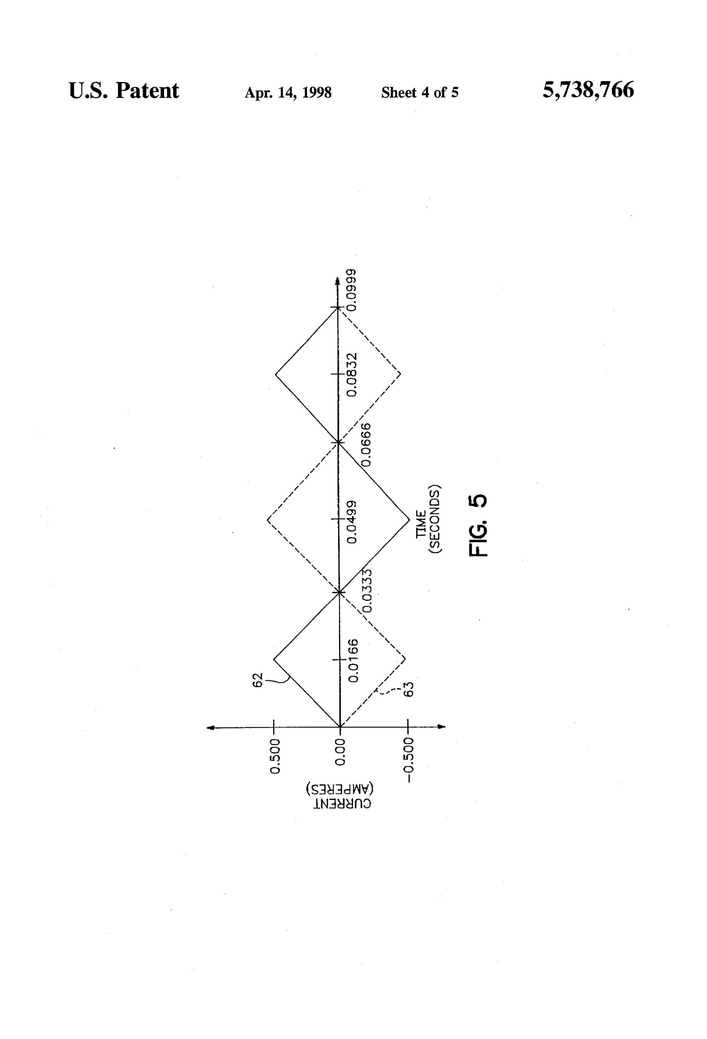
60. FIG. 4 illustrates both signals 60 and 61. FIG. 6 After winding coil 14 on conduit 12, connectors 22 and 24 illustrates the linear repetitive change in frequency. are inserted into connectors 32 and 34, respectively. Plug 28 As shown in FIG. 5, amplitude signals 62 and 63 are is inserted into source 18 energizing circuit 30. composed of triangular waveforms with a frequency of 15 Frequency oscillator 50, powered by signal 46, generates Hz and a peak amplitude of +500 mA. The signals have 40 frequency output signals 60 and 61. As shown in FIG. 4, linear slopes. Signal 63 leads signal 62 by y2 cycle so that signals 60 and 61 are two triangular waveforms which signal 63 appears as an inversion of signal 56. continuously vary infrequency from 2,000 to 10,000 Hz. By As shown in FIG. 7, the current output signal 64 of varying the frequency between a minimum and maximum, waveform integrator 48 varies in frequency and amplitude device 10 can effectively treat the water without regard to with the positive and negative amplitude peaks 65. 66 45 nearby electromagnetic sources that might otherwise inter generally lying on an envelope 67 defined by two interacting fere with and cancel out the generated field. Varying the triangular waveforms 68 and 69, which are inversions of frequency of the signal output also varies the strength and each other. Waves 68 and 69 have the shape of signals 62 and speed at which the fields change direction which improves 63 shown in FIG. 5. the effectiveness of descaling.
The output signal 64 continuously varies in frequency FIG. 4 shows signals 60 and 61 with respect to a time axis according to signals 60 and 61. Output signal 64 is a and voltage axis. At point 70, the time is 0 seconds and complex waveform that varies in frequency in step with the rises signals 60 and 61 have a frequency of 2000 Hz. Signal 60 frequency change of signals 60 and 61 and varies in peak a peaktovoltage a peak voltage of 0.1 volts while signal 55 falls to of -0.1 volts. Once the signals reach the peak amplitude in step with the amplitude change of signals 62 and 63. The waveform of output signal 64 is a generally 55 voltages, signal falls to voltage -0.1 volts while signal 55 triangular wave with steep linear slopes extending up to a rises to voltage 0.1 volts. At point 76, the time is 0.089 positive peak amplitude 65 and then steep linear slopes seconds and signals 54 and 55 are at afrequency of 6000 Hz. extending down to a negative peak amplitude 66. The value At point 82, the time is 0.178 seconds and signals 54 and 55 of the peak amplitudes 65 and 66 vary with time and are are at a frequency of 10000 Hz.
defined by envelope 67. The value of the slope is constantly Waveform oscillator 52 generates amplitude output sig changing due to the constantly changing peak amplitude and nals 62 and 63. As shown in FIG. 5, signals 62 and 63 are frequency during the rise and fall of the signal. FIG. 7 is a two triangular waveforms that form a diamond shaped wave representation of output 58 showing the change infrequency and continuously vary in peak amplitude from 0 mA to 500 and amplitude. Because the frequency and amplitude are mAback to 0 mA in one cycle with a frequency of 30 cycles continuously changing, the sides of the individual waves 65 per Second.
may be slightly bowed up or down between peaks. FIG. 7 By using signals 62 and 63 to vary the amplitude of the shows straight wave sides for convenience. FIG. 7 output signal between a minimum and maximum,
Page 9
device 10 can effectively treats a variety of molecules in the amplitude, the calcium and bicarbonate molecules experi water. Different size molecules react differently to various ence mechanical agitation when passing through the field. field strengths. Varying the amplitude of the signal output The mechanical agitation causes nucleation of the calcium varies the strength of the field which improves the effec and bicarbonate ions and formation of calcium carbonate tiveness of the descaling operation allowing treatment of a crystals. The newly formed crystals are electrically neutral variety of impurities. and do not adhere to conduit 12. In addition, the water molecules
FIG. 5 shows signals 62 and 63 with respect to a time axis scales alreadyare attracted to calcium-hydrogen carbonate and current axis. At 0 seconds, signals 62 and 63 have a water moleculesadhered as they flow along conduit 12. The amplitude of 0 mA. Signal 62 rises to a peak amplitude of ate Scale returning the scalewith then bond
calcium-hydrogen carbon solution in the water and 500 mA while signal 63 falls to a peak amplitude of -500 10 forming calcium and bicarbonate ions. When the ions pass mA. Signals 62 and 63 reach amplitudes 500 mA at 0.0166 through the field, neutral calcium carbonate scales are seconds. Signal 62 falls towards amplitude -500 mA while formed as described above.
signal 63 rises to amplitude 500 mA. Both signals reach While Ihave illustrated and described a preferred embodi amplitude 0 mA at point 72 where time is 0.0333 seconds. ment of my invention, it is understood that this is capable of
At 0.04999 seconds and signal 62 is at amplitude-500 mA modification, and Itherefore do not wish to be limited to the while signal 63 is at amplitude 500 mA. precise details set forth, but desire to avail myself of such Waveformintegrator 48, powered by signal 46, integrates changes and alterations as fall within the purview of the signals 60-63 generating circuit output signal 64. As shown following claims.
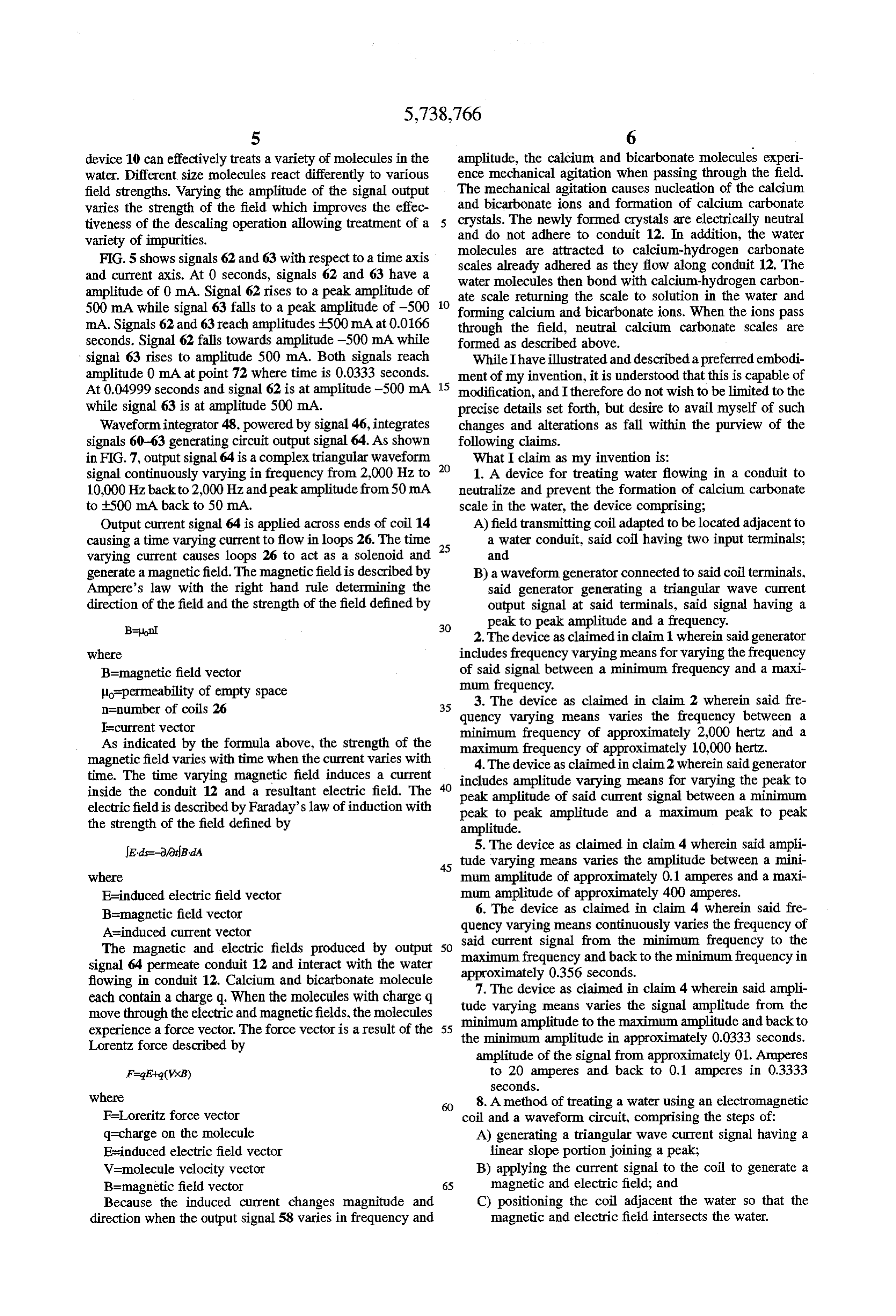
in FIG. 7, output signal 64 is a complex triangular waveform What I claim as my invention is: signal continuously varying in frequency from 2,000 Hz to 1. A device for treating water flowing in a conduit to 10,000Hz back to 2,000 Hz, and peakamplitude from 50 mA neutralize and prevent the formation of calcium carbonate to 500 mA back to 50 mA. scale in the water, the device comprising; Output current signal 64 is applied across ends of coil 14 A) field transmitting coil adapted to be located adjacent to causing a time varying current to flow in loops 26. The time 25 a water conduit, said coil having two input terminals; varying current causes loops 26 to act as a solenoid and and generate a magnetic field. The magnetic field is described by B) a waveform generator connected to said coil terminals, Ampere's law with the right hand rule determining the said generator generating a triangular wave current direction of the field and the strength of the field defined by output signal at said terminals, said signal having a 30 peak to peak amplitude and a frequency.
2. The device as claimed in claim 1 wherein said generator
Where includes frequency varying means for varying the frequency B=magnetic field vector of said signal between a minimum frequency and a maxi lo-permeability of empty space mum frequency.
3. The device as claimed in claim 2 wherein said fre n=number of coils 26 35 quency varying means varies the frequency between a
Is current vector minimum frequency of approximately 2,000 hertz and a As indicated by the formula above, the strength of the maximum frequency of approximately 10,000 hertz. magnetic field varies with time when the current varies with 4. The device as claimed in claim2 wherein said generator time. The time varying magnetic field induces a current includes amplitude varying means for varying the peak to inside the conduit 12 and a resultant electric field. The peak amplitude of said current signal between a minimum electric field is described by Faraday's law of induction with peak to peak amplitude and a maximum peak to peak the strength of the field defined by amplitude.
JEds=-datib-da 5. The device as claimed in claim 4 wherein said ampli 45 tude varying means varies the amplitude between a mini where mum amplitude of approximately 0.1 amperes and a maxi E=induced electric field vector mum amplitude of approximately 400 amperes. B=magnetic field vector 6. The device as claimed in claim 4 wherein said fre A-induced current vector quency varying means continuously varies the frequency of The magnetic and electric fields produced by output 50 maximum said current signal from the minimum frequency to the signal 64 permeate conduit 12 and interact with the water approximately frequency and back to the minimum frequency in flowing in conduit 12. Calcium and bicarbonate molecule 0.356 seconds.
7. The each contain a charge q. When the molecules with charge q tude varying meansdevice as claimed in claim 4 wherein said ampli move through the electric and magnetic fields, the molecules minimum amplitude tovaries the the signal amplitude from the maximum amplitude and back to experience a force vector. The force vector is a result of the the minimum amplitude in approximately
Lorentz force described by amplitude of the signal from approximately 01. Amperes to 20 amperes and back to 0.1 amperes in 0.3333
Seconds.
where 8. A method of treating a water using an electromagnetic F=Loreritz force vector coil and a waveform circuit, comprising the steps of: q=charge on the molecule A) generating a triangular wave current signal having a Ee-induced electric field vector linear slope portion joining a peak; V=molecule velocity vector B) applying the current signal to the coil to generate a B=magnetic field vector 65 magnetic and electric field; and Because the induced current changes magnitude and C) positioning the coil adjacent the water so that the direction when the output signal 58 varies in frequency and magnetic and electric field intersects the water.
Page 10
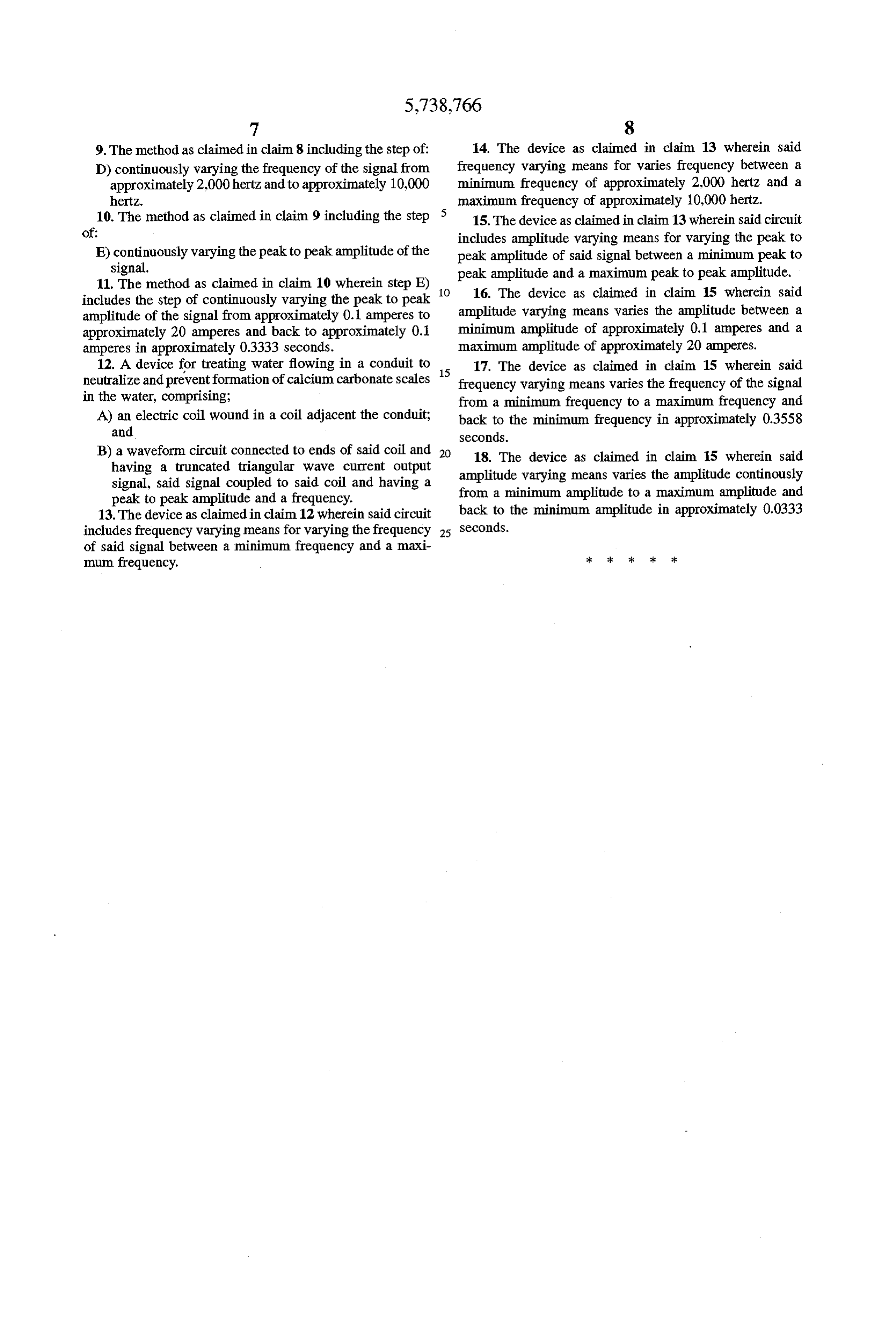
9. The method as claimed in claim 8 including the step of: 14. The device as claimed in claim 13 wherein said D) continuously varying the frequency of the signal from frequency varying means for varies frequency between a approximately 2,000 hertz and to approximately 10,000 minimum frequency of approximately 2,000 hertz and a hertz. maximum frequency of approximately 10,000 hertz. 10. The method as claimed in claim 9 including the step 15. The device as claimed in claim 13 wherein said circuit of: includes amplitude varying means for varying the peak to E) continuously varying the peak to peak amplitude of the peak amplitude of said signal between a minimum peak to signal. peak amplitude and a maximum peak to peak amplitude. 11. The method as claimed in claim 10 wherein step E) 16. The device as claimed in claim 15 wherein said includes the step of continuously varying the peak to peak amplitude of the signal from approximately 0.1 amperes to amplitude varying means varies the amplitude between a approximately 20 amperes and back to approximately 0.1 minimum amplitude of approximately 0.1 amperes and a amperes in approximately 0.3333 seconds. maximum amplitude of approximately 20 amperes. 12. A device for treating water flowing in a conduit to 17. The device as claimed in claim 15 wherein said neutralize and preventformation of calcium carbonate scales 15 frequency varying means varies the frequency of the signal in the water, comprising: from a minimum frequency to a maximum frequency and A) an electric coil wound in a coil adjacent the conduit; back to the minimum frequency in approximately 0.3558 and Seconds.
B) a waveform circuit connected to ends of said coil and 20 18. The device as claimed in claim 15 wherein said having a truncated triangular wave current output amplitude varying means varies the amplitude continously signal, said signal coupled to said coil and having a from a minimum amplitude to a maximum amplitude and peak to peak amplitude and a frequency.
13. The device as claimed in claim 12 wherein said circuit back to the minimum amplitude in approximately 0.0333 includes frequency varying means for varying the frequency 25 Seconds.
of said signal between a minimum frequency and a maxi mum frequency.
Page 11
UNITED STATES PATENT AND TRADEMARK OFFICE
CERTIFICATE OF CORRECTION
INVENTOR(S) : George N. Jefferson it is certified that error appears in the above-indentified patent and that said Letters Patent is hereby Corrected as shown below:
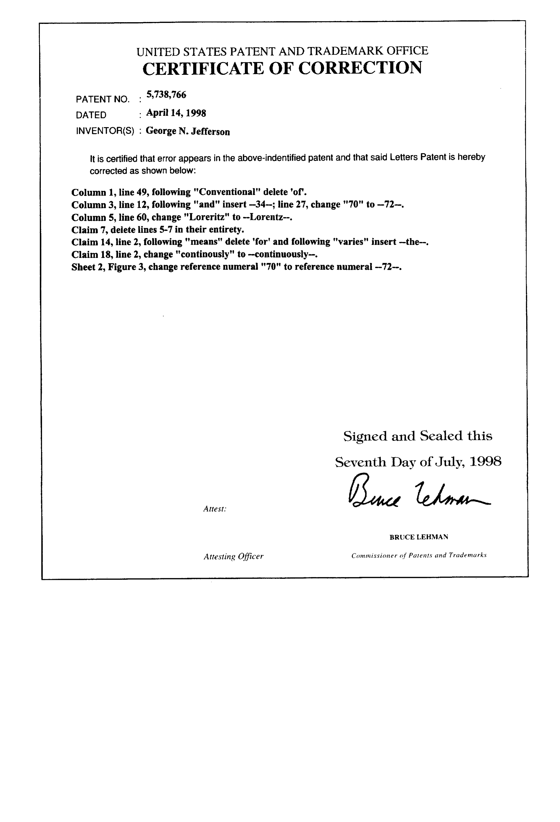
Column 1, line 49, following "Conventional" delete "of".
Column 3, line 12, following "and" insert-34-; line 27, change "70" to -72-. Column 5, line 60, change "Loreritz" to -Lorentz-.
Claim 7, delete lines 5-7 in their entirety.
Claim 14, line 2, following "means" delete 'for' and following "varies" insert-the Claim 18, line 2, change "continously" to -continuously
Sheet 2, Figure 3, change reference numeral "70" to reference numeral -72-.
Signed and Sealed this
Seventh Day of July, 1998
BRUCE LEHMAN
Attesting Officer Commissioner of Patents and Trade marks
Provenance
- Collection
- Cited prior art
- Original PDF
- patentimages.storage.googleapis.com →
- Filed
- 1996-05-17
- Pages
- 11
- Method
- pdftotext (the PDF's own text layer) + pdftoppm 300dpi page scans
- Source
- Google Patents bibliographic record
- Granted
- 1998-04-14
- Inventors
- George Nathan Jefferson; Jefferson Nathan Enterprises Inc
- Transcribed from
- patentimages.storage.googleapis.com →