patent · US3908753
Freezing-warming apparatus
30 September 1975
Page 1 — bibliographic record
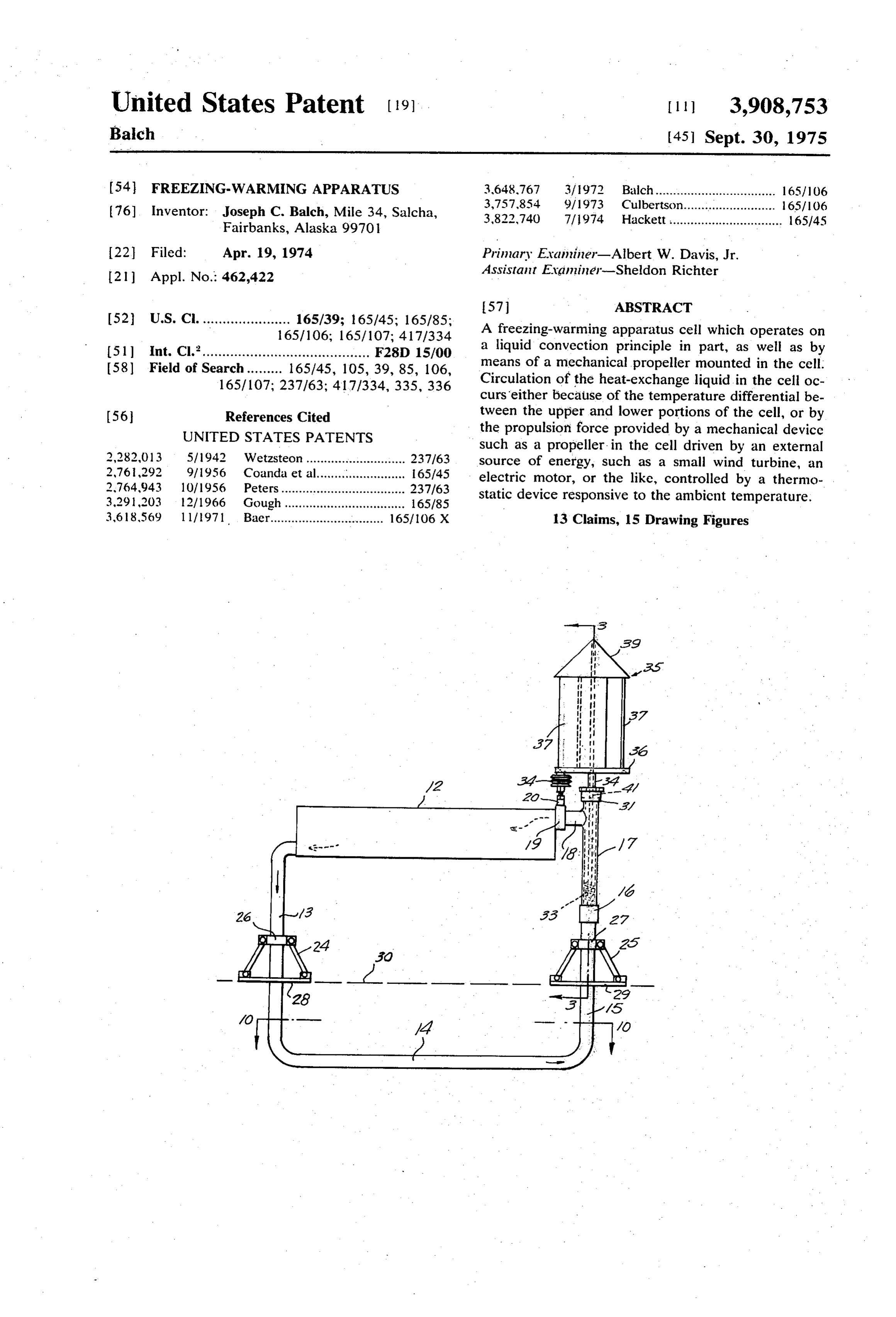
United States Patent (19) [11] 3,908,753 Balch (45) Sept. 30, 1975
54 FREEZING-WARMING APPARATUS 3,648,767 3/1972 Balch.................................. 165/106 3,757,854 9/1973 Culbertson.......................... 65/106 76) Inventor: Joseph C. Balch, Mile 34, Salcha, 3,822,740 23: E.C. FS Fairbanks, Alaska 99701 22 Filed: Apr. 19, 1974 Primary Examiner-Albert W. Davis, Jr. 21 Appl. No.: 462,422 Assistant Evaminer-Sheldon Richter
52 U.S. Cl.................... 6 i?: S; E. A freezing-warming apparatus cell which operates on 51 Int. C. y F2sD 15/00 a liquid convection principle in part, as well as by id isearch - - - - - - - - - - -ió5/45, 05, 39, 85, 106 means of a mechanical propeller mounted in the cell. rea or se 0.737. Circulation of the heat exchange liquid in the cell oc curs either because of the temperature differential be tween the upper and lower portions of the cell, or by (56 References Cited the propulsion force provided by a mechanical device UNITED STATES PATENTS such as a propeller in the cell driven by an external 2,282,013 5/1942 Wetzsteon............................ 237/63 Source of energy, such as a small wind turbine, an 2,76,292 9/1956 Coanda et al......................... 165/45 electric motor, or the like, controlled by a thermo 2,764,943 10/1956 Peters................................... 237/63 static device responsive to the ambient temperature. 3.291,203 12/1966 Gough.................................. 165/85 3,618,569 l l 1971. Baer................................ 165/106 X 13 Claims, 15 Drawing Figures
Page 2
Drawing sheet — no readable text.
Page 3
Drawing sheet — no readable text.
Page 4
Drawing sheet — no readable text.
Page 5
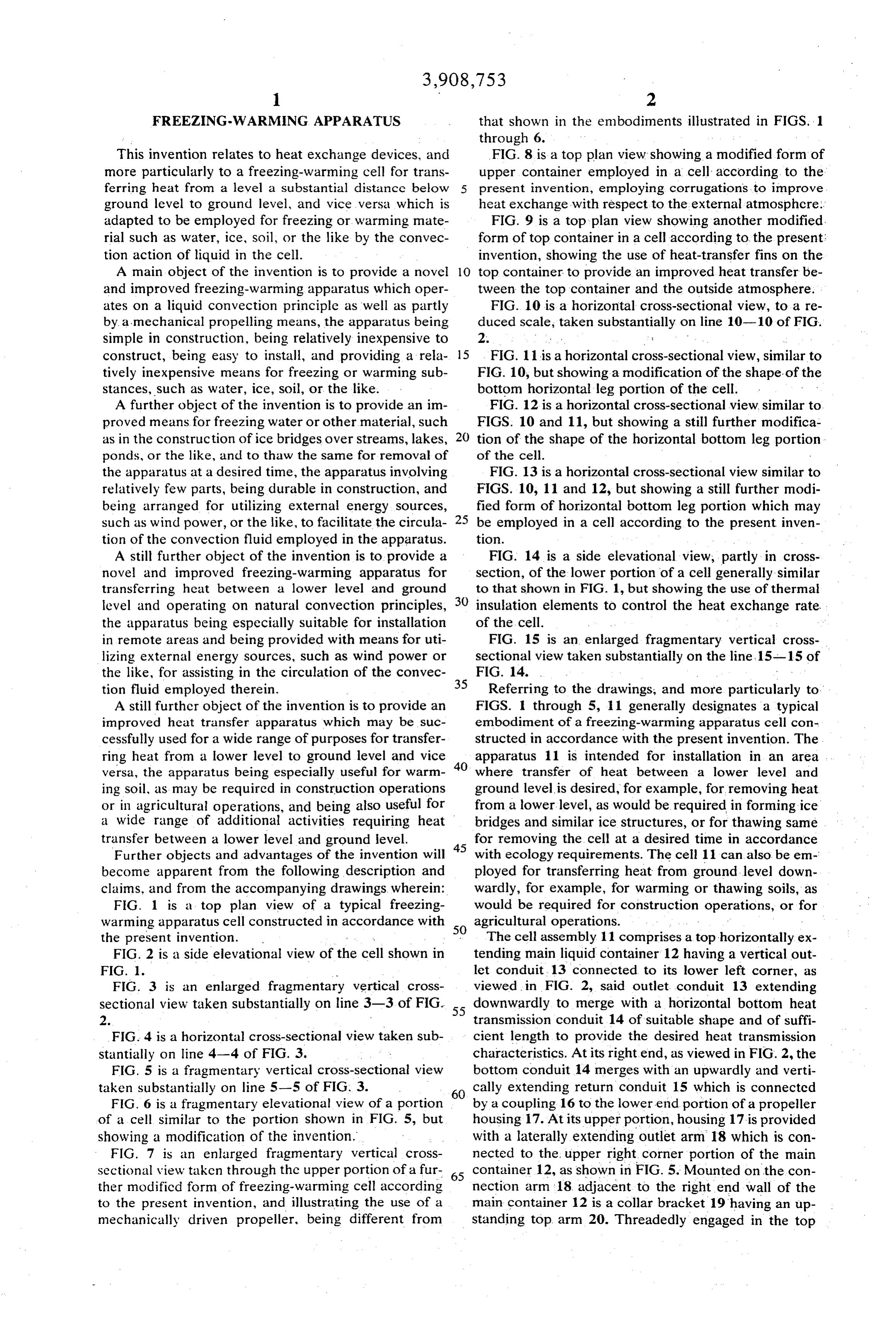
FREEZING-WARMING APPARATUS that shown in the embodiments illustrated in FIGS. 1 through 6.
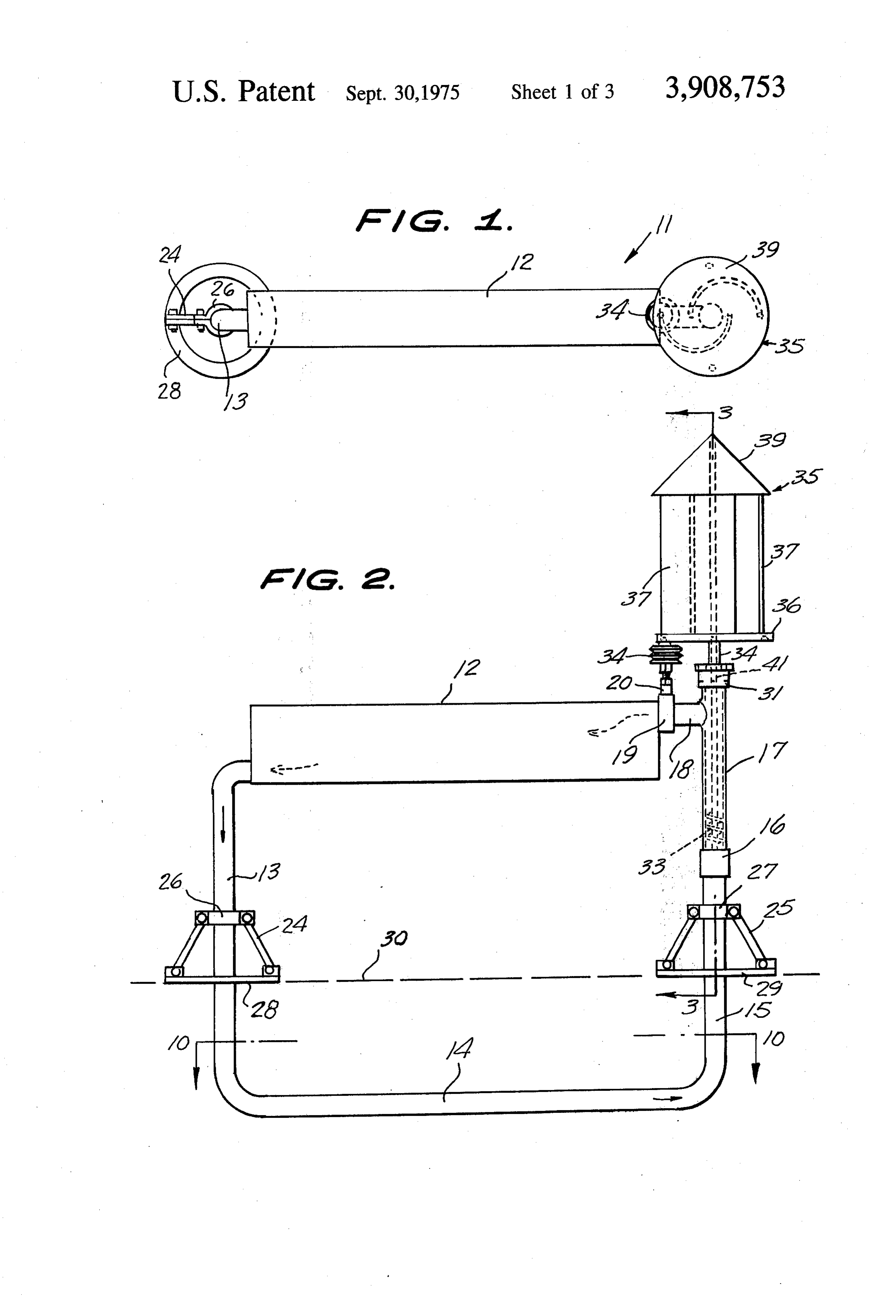
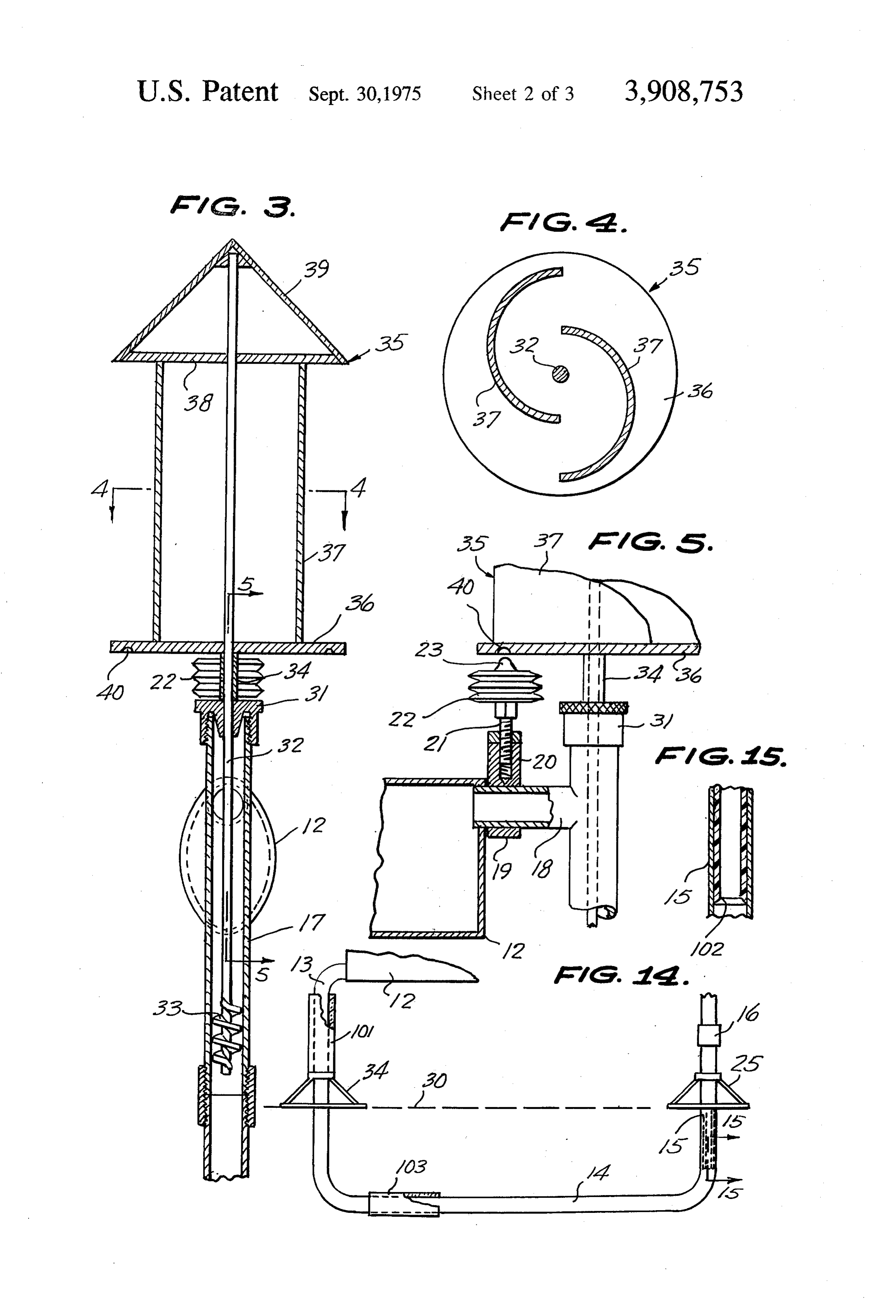
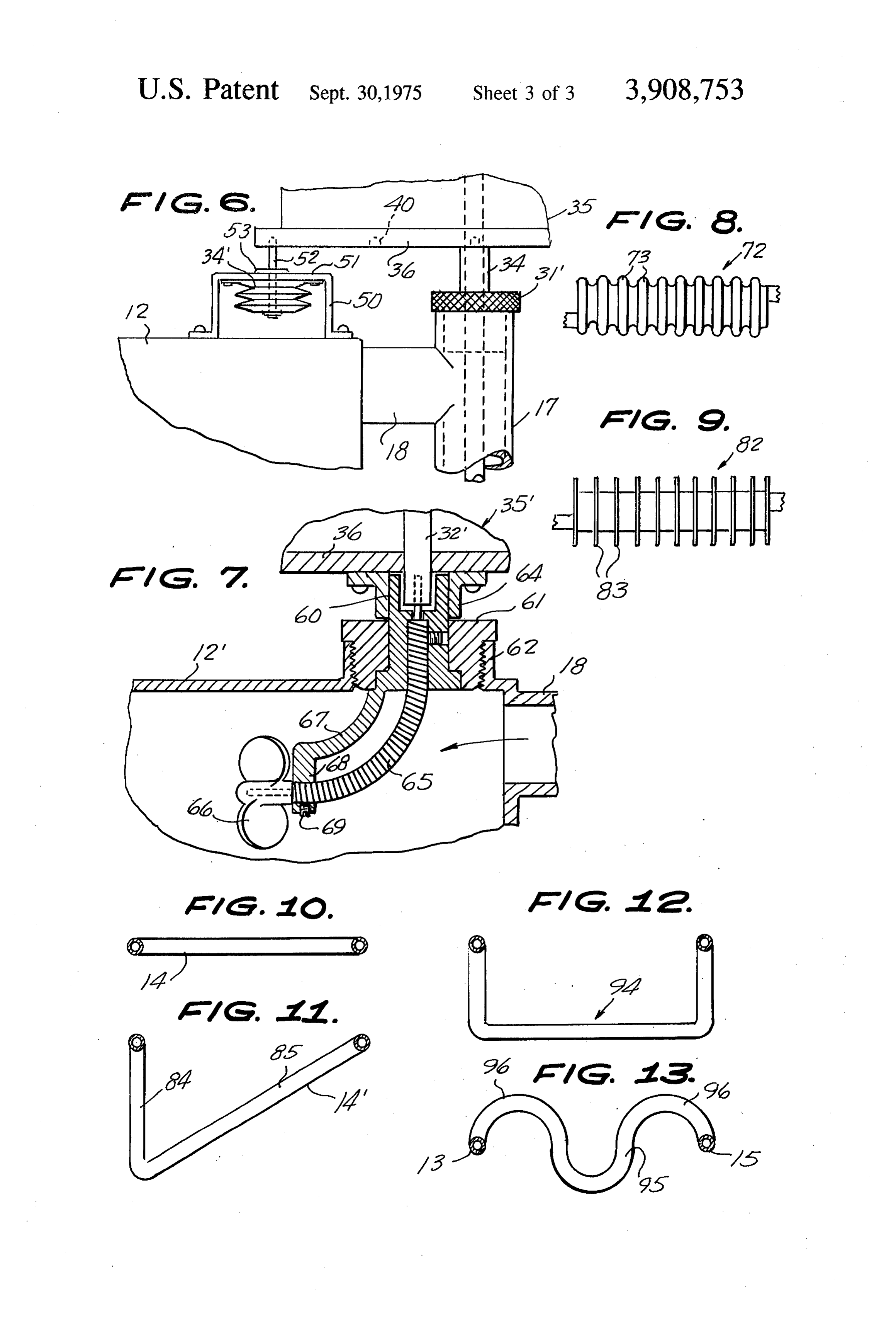
This invention relates to heat exchange devices, and FIG. 8 is a top plan view showing a modified form of more particularly to a freezing-warming cell for trans upper container employed in a cell according to the ferring heat from a level a substantial distance below present invention, employing corrugations to improve ground level to ground level, and vice versa which is heat exchange with respect to the external atmosphere. adapted to be employed for freezing or warming mate FIG. 9 is a top plan view showing another modified. rial such as water, ice, soil, or the like by the convec form of top container in a cell according to the present: tion action of liquid in the cell. invention, showing the use of heat-transfer fins on the A main object of the invention is to provide a novel 10 top container to provide an improved heat transfer be and improved freezing-warming apparatus which oper tween the top container and the outside atmosphere. ates on a liquid convection principle as well as partly FIG. 10 is a horizontal cross-sectional view, to a re by a mechanical propelling means, the apparatus being duced scale, taken substantially on line 10-10 of FIG. simple in construction, being relatively inexpensive to 2. X
construct, being easy to install, and providing a rela 15 FIG. 11 is a horizontal cross-sectional view, similar to tively inexpensive means for freezing or warming sub FIG. 10, but showing a modification of the shape of the stances, such as water, ice, soil, or the like. bottom horizontal leg portion of the cell. . A further object of the invention is to provide an im FIG. 12 is a horizontal cross-sectional view, similar to proved means for freezing water or other material, such FIGS. 10 and 11, but showing a still further modifica as in the construction of ice bridges over streams, lakes, 20 tion of the shape of the horizontal bottom leg portion ponds, or the like, and to thaw the same for removal of of the cell.
the apparatus at a desired time, the apparatus involving FIG. 13 is a horizontal cross-sectional view similar to relatively few parts, being durable in construction, and FIGS. 10, 11 and 12, but showing a still further modi being arranged for utilizing external energy sources, fied form of horizontal bottom leg portion which may such as wind power, or the like, to facilitate the circula 25 be employed in a cell according to the present inven tion of the convection fluid employed in the apparatus. tion.
A still further object of the invention is to provide a FIG. 14 is a side elevational view, partly in cross novel and improved freezing-warming apparatus for section, of the lower portion of a cell generally similar transferring heat between a lower level and ground to that shown in FIG. 1, but showing the use of thermal level and operating on natural convection principles, insulation elements to control the heat exchange rate. the apparatus being especially suitable for installation of the cell.
in remote areas and being provided with means for uti FIG. 15 is an enlarged fragmentary vertical cross lizing external energy sources, such as wind power or sectional view taken substantially on the line, 15-15 of the like, for assisting in the circulation of the convec 35 FIG. 14. • tion fluid employed therein. Referring to the drawings, and more particularly to FIGS. I through 5, 11 generally designates a typical
A still further object of the invention is to provide an improved heat transfer apparatus which may be suc embodiment of a freezing-warming apparatus cell con cessfully used for a wide range of purposes for transfer structed in accordance with the present invention. The ring heat from a lower level to ground level and vice apparatus 11 is intended for installation in an area versa, the apparatus being especially useful for warm 40 where transfer of heat between a lower level and ing soil, as may be required in construction operations ground level is desired, for example, for removing heat or in agricultural operations, and being also useful for from a lower level, as would be required in forming ice a wide range of additional activities requiring heat bridges and similar ice structures, or for thawing same transfer between a lower level and ground level. for removing the cell at a desired time in accordance Further objects and advantages of the invention will 45 with ecology requirements. The cell 11 can also be em become apparent from the following description and ployed for transferring heat from ground-level down claims, and from the accompanying drawings, wherein: wardly, for example, for warming or thawing soils, as FIG. 1 is a top plan view of a typical freezing would be required for construction operations, or for warming apparatus cell constructed in accordance with agricultural operations.
the present invention. - . 50 The cell assembly 11 comprises a top horizontally ex FIG. 2 is a side elevational view of the cell shown in tending main liquid container 12 having a vertical out FIG 1. let conduit, 13 connected to its lower left corner, as FIG. 3 is an enlarged fragmentary vertical cross viewed in FIG. 2, said outlet conduit 13 extending sectional view taken substantially on line 3-3 of FIG. 55 downwardly to merge with a horizontal bottom heat 2. transmission conduit 14 of suitable shape and of suffi FIG. 4 is a horizontal cross-sectional view taken sub cient length to provide the desired heat transmission stantially on line 4-4 of FIG. 3. characteristics. At its right end, as viewed in FIG. 2, the FIG. 5 is a fragmentary vertical cross-sectional view bottom conduit 14 merges with an upwardly and verti taken substantially on line 5-5 of FIG. 3. 60 cally extending return conduit 15 which is connected FIG. 6 is a fragmentary elevational view of a portion by a coupling 16 to the lower end portion of a propeller of a cell similar to the portion shown in FIG. 5, but housing 17. At its upper portion, housing 17 is provided showing a modification of the invention. with a laterally extending outlet arm 18 which is con FIG. 7 is an enlarged fragmentary vertical cross nected to the upper right corner portion of the main sectional view taken through the upper portion of a fur 65 container 12, as shown in FIG. 5. Mounted on the con ther modified form of freezing-warming cell according nection arm 18 adjacent to the right end wall of the to the present invention, and illustrating the use of a main container 12 is a collar bracket 19 having an up mechanically driven propeller, being different from standing top arm 20. Threadedly engaged in the top
Page 6
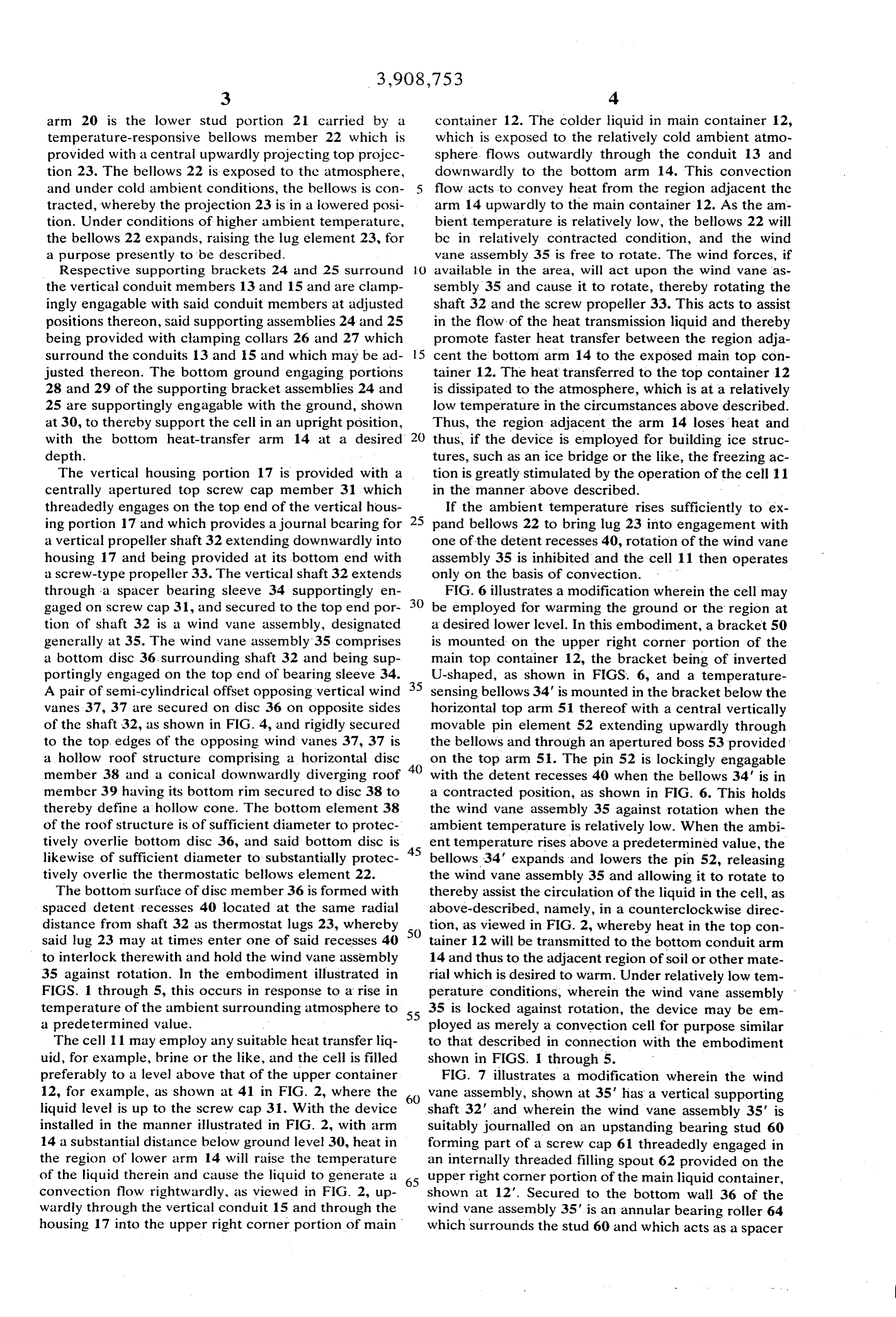
arm 20 is the lower stud portion 21 carried by a container 12. The colder liquid in main container 12, temperature-responsive bellows member 22 which is which is exposed to the relatively cold ambient atmo provided with a central upwardly projecting top projec sphere flows outwardly through the conduit 13 and tion 23. The bellows 22 is exposed to the atmosphere, downwardly to the bottom arm 14. This convection and under cold ambient conditions, the bellows is con 5 flow acts to convey heat from the region adjacent the tracted, whereby the projection 23 is in a lowered posi arm 14 upwardly to the main container 12. As the am tion. Under conditions of higher ambient temperature, bient temperature is relatively low, the bellows 22 will the bellows 22 expands, raising the lug element 23, for be in relatively contracted condition, and the wind a purpose presently to be described. vane assembly 35 is free to rotate. The wind forces, if Respective supporting brackets 24 and 25 surround O available in the area, will act upon the wind vane as the vertical conduit members 13 and 15 and are clamp sembly 35 and cause it to rotate, thereby rotating the ingly engagable with said conduit members at adjusted shaft 32 and the screw propeller 33. This acts to assist positions thereon, said supporting assemblies 24 and 25 in the flow of the heat transmission liquid and thereby being provided with clamping collars 26 and 27 which promote faster heat transfer between the region adja surround the conduits 13 and 15 and which may be ad 5 cent the bottom arm 14 to the exposed main top con justed thereon. The bottom ground engaging portions tainer 12. The heat transferred to the top container 12 28 and 29 of the supporting bracket assemblies 24 and is dissipated to the atmosphere, which is at a relatively 25 are supportingly engagable with the ground, shown low temperature in the circumstances above described. at 30, to thereby support the cell in an upright position,
Thus, the region adjacent the arm 14 loses heat and with the bottom heat-transfer arm 14 at a desired 20 thus, if the device is employed for building ice struc depth. tures, such as an ice bridge or the like, the freezing ac The vertical housing portion 17 is provided with a tion is greatly stimulated by the operation of the cell 11 centrally apertured top screw cap member 31, which in the manner above described.
threadedly engages on the top end of the vertical hous If the ambient temperature rises sufficiently to ex ing portion 17 and which provides a journal bearing for 25 pand bellows 22 to bring lug 23 into engagement with a vertical propeller shaft 32 extending downwardly into one of the detent recesses 40, rotation of the wind vane housing 17 and being provided at its bottom end with assembly 35 is inhibited and the cell 11 then operates a screw-type propeller 33. The vertical shaft 32 extends only on the basis of convection. m through a spacer bearing sleeve 34 supportingly en FIG. 6 illustrates a modification wherein the cell may gaged on screw cap 31, and secured to the top end por be employed for warming the ground or the region at tion of shaft 32 is a wind vane assembly, designated a desired lower level. In this embodiment, a bracket 50 generally at 35. The wind vane assembly' 35 comprises is mounted on the upper right corner portion of the a bottom disc 36 surrounding shaft 32 and being sup main top container 12, the bracket being of inverted portingly engaged on the top end of bearing sleeve 34. U-shaped, as shown in FIGS. 6, and a temperature A pair of semi-cylindrical offset opposing vertical wind 35 sensing bellows 34' is mounted in the bracket below the vanes 37, 37 are secured on disc 36 on opposite sides horizontal top arm 51 thereof with a central vertically of the shaft 32, as shown in FIG. 4, and rigidly secured movable pin element 52 extending upwardly through to the top edges of the opposing wind vanes 37, 37 is the bellows and through an apertured boss 53 provided a hollow roof structure comprising a horizontal disc 40 on the top arm 51. The pin 52 is lockingly engagable member 38 and a conical downwardly diverging roof with the detent recesses 40 when the bellows 34' is in member 39 having its bottom rim secured to disc 38 to a contracted position, as shown in FIG. 6. This holds thereby define a hollow cone. The bottom element 38 the wind vane assembly 35 against rotation when the of the roof structure is of sufficient diameter to protec ambient temperature is relatively low. When the ambi tively overlie bottom disc 36, and said bottom disc is ent temperature rises above a predetermined value, the likewise of sufficient diameter to substantially protec bellows 34' expands and lowers the pin 52, releasing tively overlie the thermostatic bellows element 22. the wind vane assembly 35 and allowing it to rotate to The bottom surface of disc member 36 is formed with thereby assist the circulation of the liquid in the cell, as spaced detent recesses 40 located at the same radial above-described, namely, in a counterclockwise direc distance from shaft 32 as thermostat lugs 23, whereby tion, as viewed in FIG. 2, whereby heat in the top con said lug 23 may at times enter one of said recesses 40 50 tainer 12 will be transmitted to the bottom conduit arm to interlock therewith and hold the wind vane assembly 14 and thus to the adjacent region of soil or other mate 35 against rotation. In the embodiment illustrated in rial which is desired to warm. Under relatively low tem FIGS. 1 through 5, this occurs in response to a rise in perature conditions, wherein the wind vane assembly temperature of the ambient surrounding atmosphere to 55 35 is locked against rotation, the device may be em a predetermined value. ployed as merely a convection cell for purpose similar The cell 11 may employ any suitable heat transfer liq to that described in connection with the embodiment uid, for example, brine or the like, and the cell is filled shown in FIGS. 1 through 5.
preferably to a level above that of the upper container FIG. 7 illustrates a modification wherein the wind 12, for example, as shown at 41 in FIG. 2, where the 60 Vane assembly, shown at 35' has a vertical supporting liquid level is up to the screw cap 31. With the device shaft 32' and wherein the wind vane assembly 35' is installed in the manner illustrated in FIG. 2, with arm Suitably journalled on an upstanding bearing stud 60 14 a substantial distance below ground level 30, heat in forming part of a screw cap 61 threadedly engaged in the region of lower arm 14 will raise the temperature an internally threaded filling spout 62 provided on the of the liquid therein and cause the liquid to generate a 65 upper right corner portion of the main liquid container, convection flow rightwardly, as viewed in FIG. 2, up shown at 12'. Secured to the bottom wall 36 of the wardly through the vertical conduit 15 and through the wind vane assembly 35" is an annular bearing roller 64 housing 17 into the upper right corner portion of main which surrounds the stud 60 and which acts as a spacer
Page 7
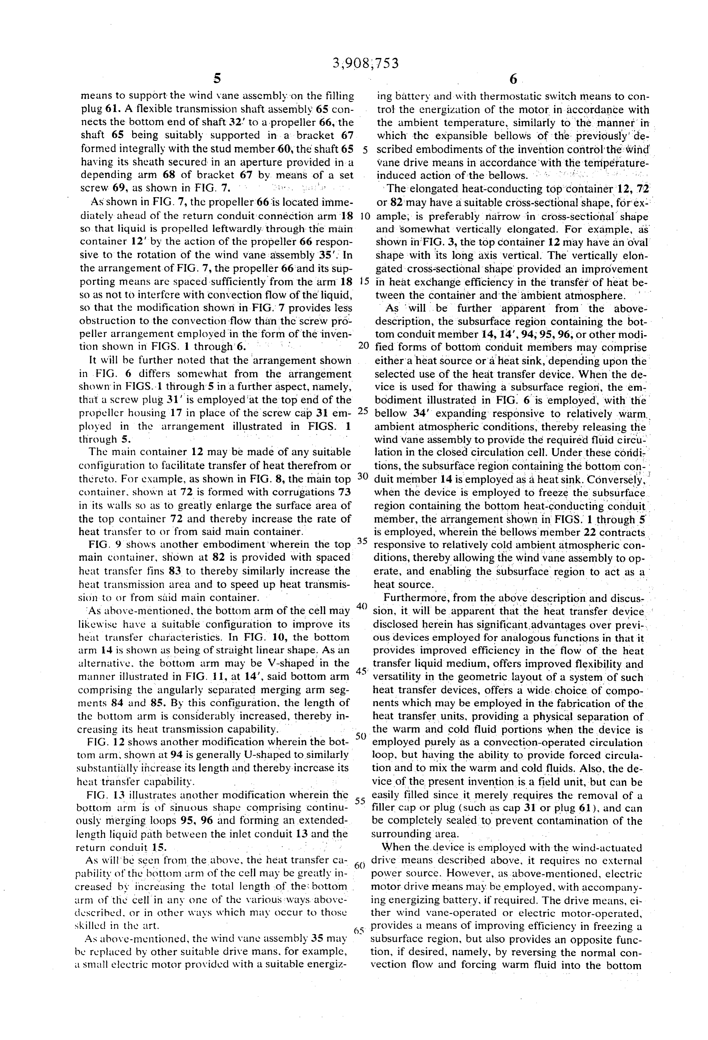
S 6 means to support the wind vane assembly on the filling ing battery and with thermostatic switch means to con plug 61. A flexible transmission shaft assembly 65 con trol the energization of the motor in accordance with nects the bottom end of shaft 32 to a propeller 66, the the ambient temperature, similarly to the manner in shaft 65 being suitably supported in a bracket 67 which the expansible bellows of the previously de formed integrally with the stud member 60, the shaft 65 scribed embodiments of the invention control the wind having its sheath secured in an aperture provided in a vane drive means in accordance with the temperature depending arm 68 of bracket 67 by means of a set induced action of the bellows. . . . . . . . . screw 69, as shown in FIG. 7. . . .. .. . .. . . . . . The elongated heat-conducting top container 12, 72 As shown in FIG. 7, the propeller 66 is located imme or 82 may have a suitable cross-sectional shape, for ex diately ahead of the return conduit connection arm 18 10 ample, is preferably narrow in cross-sectional shape so that liquid is propelled leftwardly through the main and somewhat vertically elongated. For example, as container 12' by the action of the propeller 66 respon shown in FIG. 3, the top container 12 may have an oval sive to the rotation of the wind vane assembly 35". In shape with its long axis vertical. The vertically elon the arrangement of FIG. 7, the propeller 66 and its sup gated cross-sectional shape provided an improvement porting means are spaced sufficiently from the arm 18 5 in heat exchange efficiency in the transfer of heat be so as not to interfere with convection flow of the liquid, tween the container and the ambient atmosphere. so that the modification shown in FIG.7 provides less As will be further apparent from the above obstruction to the convection flow than the screw pro description, the subsurface region containing the bot peller arrangement employed in the form of the inven tom conduit member 14, 14,94, 95, 96, or other modi tion shown in FIGS. 1 through 6. fied forms of bottom conduit members may comprise It will be further noted that the arrangement shown either a heat source or a heat sink, depending upon the in FIG. 6 differs somewhat from the arrangement selected use of the heat transfer device. When the de shown in FIGS. 1 through 5 in a further aspect, namely, vice is used for thawing a subsurface region, the em that a screw plug. 31' is employed at the top end of the bodiment illustrated in FIG. 6 is employed, with the propeller housing 17 in place of the screw cap 31 em 25 bellow 34' expanding responsive to relatively warm. ployed in the arrangement illustrated in FIGS. 1 ambient atmospheric conditions, thereby releasing the through 5. . .. . .. * . . . wind vane assembly to provide the required fluid circu The main container 12 may be made of any suitable lation in the closed circulation cell. Under these condi configuration to facilitate transfer of heat therefrom or 30 tions, the subsurface region containing the bottom con thereto. For example, as shown in FIG. 8, the main top duit member 14 is employed as a heat sink. Conversely, container, shown at 72 is formed with corrugations 73 when the device is employed to freeze the subsurface in its walls so as to greatly enlarge the surface area of region containing the bottom heat-conducting conduit the top container 72 and thereby increase the rate of member, the arrangement shown in FIGS. 1 through 5 heat transfer to or from said main container. is employed, wherein the bellows member 22 contracts FIG. 9 shows another embodiment wherein the top 35 responsive to relatively cold ambient atmospheric con main container, shown at 82 is provided with spaced ditions, thereby allowing the wind vane assembly to op heat transfer fins 83 to thereby similarly increase the erate, and enabling the subsurface region to act as a heat transmission area and to speed up heat transmis heat source.
sion to or from said main container.
Furthermore, from the above description and discus
As above-mentioned, the bottom arm of the cell may sion, it will be apparent that the heat transfer device likewise have a suitable configuration to improve its disclosed herein has significant advantages over previ heat transfer characteristics. In FIG. 10, the bottom ous devices employed for analogous functions in that it arm 14 is shown as being of straight linear shape. As an provides improved efficiency in the flow of the heat alternative, the bottom arm may be V-shaped in the transfer liquid medium, offers improved flexibility and manner illustrated in FIG. 1, at 14", said bottom arm versatility in the geometric layout of a system of such comprising the angularly separated merging arm seg heat transfer devices, offers a wide choice of compo ments 84 and 85. By this configuration, the length of nents which may be employed in the fabrication of the the bottom arm is considerably increased, thereby in heat transfer units, providing a physical separation of creasing its heat transmission capability. the warm and cold fluid portions when the device is FIG. 12 shows another modification wherein the bot 50 employed purely as a convection-operated circulation t() mann shown at 94 is generally U-shaped to similarly loop, but having the ability to provide forced circula substantially increase its length and thereby increase its tion and to mix the warm and cold fluids. Also, the de heat transfer capability. vice of the present invention is a field unit, but can be FIG. 13 illustrates another modification wherein the easily filled since it merely requires the removal of a bottom arm is of sinuous shape comprising continu filler cap or plug (such as cap 31 or plug 61), and can ously merging loops 95, 96 and forming an extended be completely sealed to prevent contamination of the length liquid path between the inlet conduit 13 and the surrounding area.
return conduit 15. . . .. . . When the device is employed with the wind-actuated As will be seen from the above, the heat transfer ca drive means described above, it requires no external pability of the bottom arm of the cell may be greatly in power source. However, as above-mentioned, electric creased by increasing the total length of the bottom. motor drive means may be employed, with accompany arm of the cell in any one of the various ways above ing energizing battery, if required. The drive means, ei described, or in other ways which may occur to those ther wind vane-operated or electric motor-operated, skilled in the art. - provides a means of improving efficiency in freezing a As above-mentioned, the wind Vane assembly 35 may subsurface region, but also provides an opposite func be replaced by other suitable drive mans, for example, tion, if desired, namely, by reversing the normal con a small electric motor provided with a suitable energiz vection flow and forcing warm fluid into the bottom
Page 8
conduit member to thereby serve as a means for thaw being drivingly connected to said propeller means, and ing material in the subsurface region containing the temperature-responsive mechanical detent means bottom conduit member. mounted on the cell in a position exposed to the ambi FIGS. 14 and 15 show how the heat exchange charac ent temperature and being at times lockingly engage teristics of various portions of the cell assembly may be 5 able with said drive means so as to control said drive controlled by employing either internal or external heat means in accordance with the ambient temperature. insulation elements with these portions. For example, 2. The heat transfer device of claim 1, wherein said the vertical externally exposed conduit portions may be depending conduits extend vertically and respective provided with heat insulation elements such as an ex surface-engaging supporting bracket members adjust ternal heat insulation sleeve 101 of selected length on () ably secured to said depending conduits for supporting the exposed portion of vertical conduit 13 above the cell in an upright position with the bottom conduit bracket 24 or an internal insulation sleeve 102 of se member at a desired depth below the surface. lected length in the vertical conduit 15 below bracket 3. The heat transfer device of claim 1, wherein said 25. Also the bottom conduit 14 may be provided with cell is provided at its top portion with a removable clo an external insulation sleeve 103 of selected length, as 5 sure member and wherein said drive means comprises shown. As will be apparent, any or all of the illustrated a rotary wind vane member rotatably mounted on the insulation sleeve elements may be employed, and their cell and driving, shaft means extending rotatably locations or lengths may be varied in accordance with through said closure member and drivingly connecting the requirements of the particular installation. said wind vane member to the propeller means. Under certain conditions, such as in using the appa 4. The heat transfer device of claim 1, and heat insu ratus of the present invention for warming or thawing lation means partially covering at least one of the de subsoil, or the like, some means or method of use is re pending conduits. W quired to prevent a continuous convection flow when 5. The heat transfer device of claim 1, and heat insu the ambient air is below freezing. Therefore, in order lation means in the interior of and in thermal shielding to prevent refreeze from taking place by convection 25 relation with at least one of the depending conduits. flow, flow must be prevented by suitable valving or 6. The heat transfer device of claim 1, and heat insu other means of shutting off flow of the liquid. In the ap lation means partially covering said bottom heat paratus of the present invention, this can be accom conducting conduit members.
plished by reducing the amount of liquid in the top con 7. The heat transfer device of claim 1, and heat insu tainer 12 to a level slightly below that of the feed con lation means mounted in thermal shielding relation duit 18. Under these conditions, the propeller 33 (FIG. with a portion of the conduit circuit branch comprising 2) can still provide the necessary propulsion to produce said depending conduits and said bottom conduit mem the required normal liquid flow (counterclockwise, as ber. m
viewed in FIG. 2), to maintain circulation of the liquid 8. The heat transfer device of claim 1, wherein said for warming or thawing the subsoil. drive means comprises a rotary wind vane member ro When certain specific embodiments of an improved tatably mounted on the cell adjacent said top con heat transfer device for conveying heat between the tainer.
ambient temperature and a subsurface region have 9. The heat transfer device of claim 8, and wherein been disclosed in the foregoing description, it will be said detent means comprises a heat-responsive expansi understood that various modifications within the spirit 40 ble member mounted on the cell adjacent said wind of the invention may occur to those skilled in the art. vane member and having a detent element at times en Therefore, it is intended that no limitations be placed gageable with said wind vane member to inhibit rota on the invention except as defined by the scope of the tion of the wind vane member. appended claims. 10. The heat transfer device of claim 9, wherein said What is claimed is: 45 wind vane member is coaxially mounted relative to one 1. A heat transfer device for conveying heat between of said depending conduits and said propeller means the ambient atmosphere and a sub-surface region com comprises a screw propeller rotatably mounted coaxi prising an elongated bottom heat-conducting conduit ally in said one of the depending conduits and having member disposed in said sub-surface region, an elon a common shaft with said wind vane member. gated top heatconducting container exposed to the am 50 11. The heat transfer device of claim 9, wherein said bient atmosphere and having depending conduits at its wind vane member includes a bottom disc element hav opposite ends, said conduits extending downwardly and ing detent recesses located to receive said detent ele being connected to the respective opposite ends of said ment.
bottom conduit member, forming a closed-circuit cir 12. The heat transfer device of claim 11, wherein said culation cell, a liquid heat-transfer medium in said expansible member is vertically mounted and said de closed-circuit circulation cell and filling said cell suffi tent recesses are located in the bottom surface of said ciently to allow circulatory convection flow through disc element.
said closedcircuit cell responsive to exposure of said 13. The heat transfer device of claim 12, wherein said top heat-conducting container to temperatures lower wind Vane member is provided with a top cover ele than that of the subsurface region containing said bot 60 ment of sufficient size to overlie said disc element and tom conduit member, propeller means rotatably to substantially protectively overlie the heat-responsive mounted in a portion of said closed-circuit cell for forc expansible member.
ing circulation, drive means mounted on the cell and k k sk ck sk
Provenance
- Collection
- Cited prior art
- Original PDF
- patentimages.storage.googleapis.com →
- Filed
- 1974-04-19
- Pages
- 8
- Method
- pdftotext (the PDF's own text layer) + pdftoppm 300dpi page scans
- Source
- Google Patents bibliographic record
- Granted
- 1975-09-30
- Inventors
- Joseph C Balch
- Transcribed from
- patentimages.storage.googleapis.com →