patent · US2506951
Foraminous sheet material and luminaire made therefrom
9 May 1950
Page 1
Drawing sheet — no readable text.
Page 2
Drawing sheet — no readable text.
Page 3
Patented May 9, 1950 2,506.951
UNITED STATES PATENT OFFICE
FORAMINOUS SHEET MATERIAL AND
LUMNARE MADE THEREFROM
Leroy C. Doane, Essex, Conn.
Application November 5, 1945, serial No. 626,747
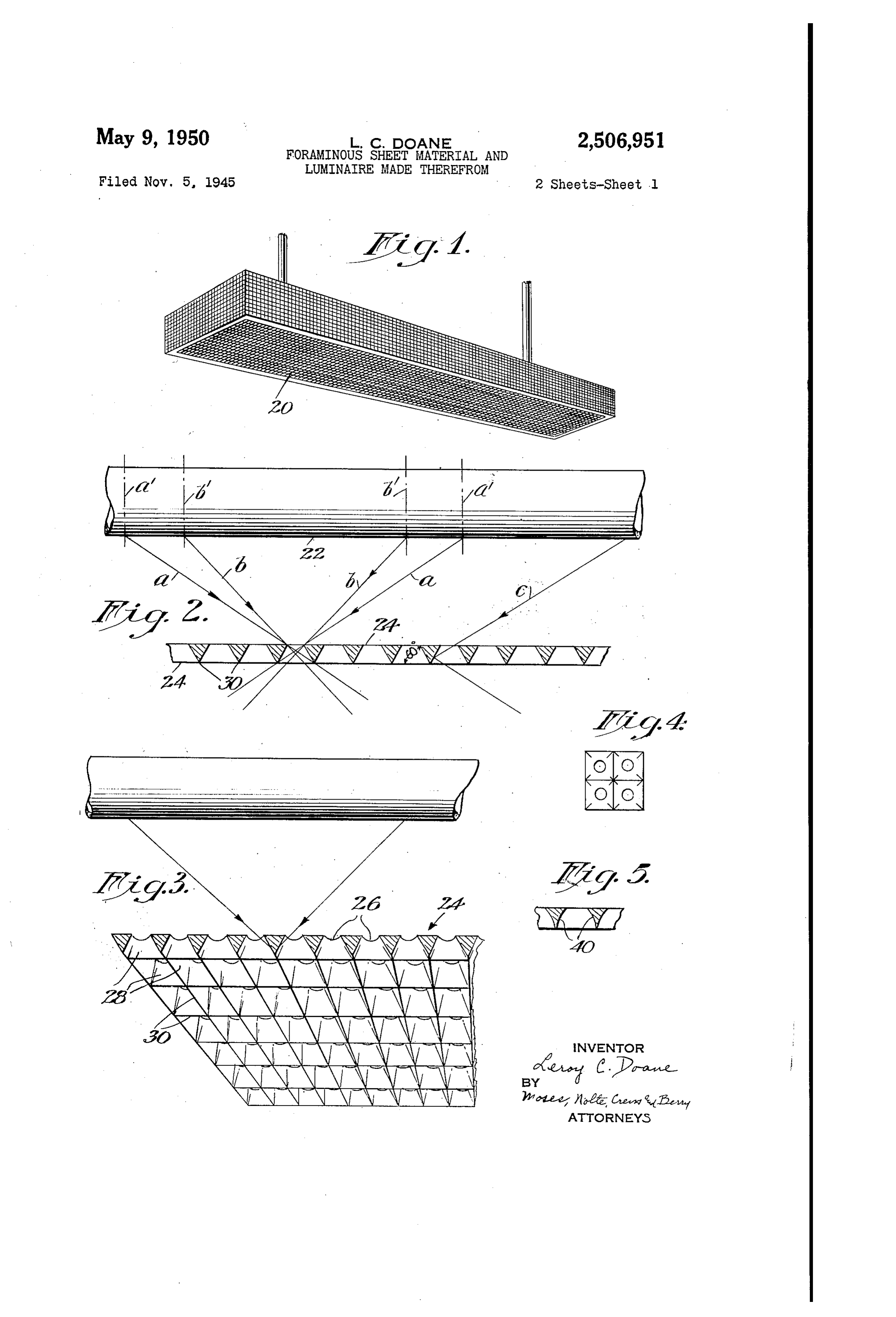
This invention relates to foraminous or per tain preferred embodinents of the invention, are forated sheet material which will transmit a Sub illustrative of the principles thereof. .. stantial annount of light, through the same and Fig. 1 is a perspective view of a conventional which is useful for illuminating devices, Such lighting fixture or inningire made of the in aS lighting fixtures or luminaries, electric signs, proved foraminous laterial. • and Signiar uses. The invention also relates to Fig. 2 is a diagraminatic view in longitudinal lighting devices made from the novel material. Section showing a portion of a fluorescent tube It has heretofore been proposed to use per and a sheet, of the improved material below the forated Sheet metal for making lighting fixtures Sane, illustrating the paths of light rays. and signs. While such perforated sheet metal Fig. 3 is a VieW ShoWing a sheet of the nate transmits a fair percentage of the light and is rial in pairspective as viewed from the underside, capable of prodicing pleasing effects, much of and showing a portion of the fuorescent tube. the light is cut off or is lost by cross reflection in Fig. 4 is a plan view of the outside of a piece the perforations and the sheets have the disad of the materia.
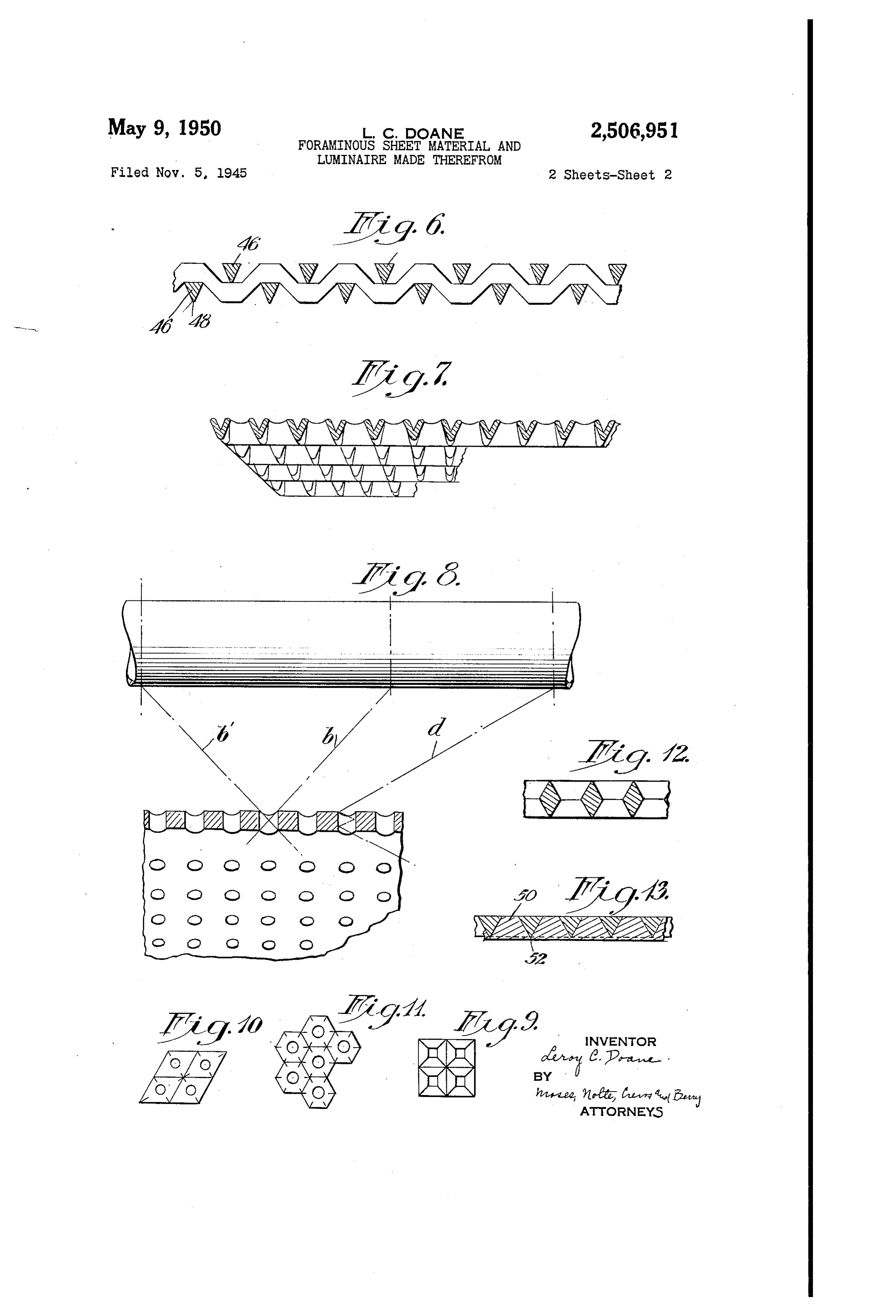
vantage that the outer Surface thereof does not 5 Fig. 5 is a transverse Sectional view of a sheet receive direct rays of light and therefore presents showing a modified form of perforation. a dark appearance, detracting from the desired Fig. 6 is a transverse Sectional view of a Woven trainous effect of the entire fixture or sign. . This Wire nesh fabric having Some of the characteris is due to the fact that the side Walls of the per tics of the perforated sheet shown in Figs. 2 and 3. forations are parallel and therefore do not effec 20 Fig. 7 is a sectional perspective view, showing tively reflect the rays out of the fixture. Also, the underside of a modified form of perforated the outer surface of the imperforate part of the Sheet.
sheet which constitutes the greater: part of the Fig. 3 is a diagrammatic view similar to Fig. 2, area, is not directly illuminated and therefore 25 showing the action of the light rays in connec presents a dark appearance. It is the object of tion with the conventional perforated sheet of the present invention: to overcome these defects the prior art.
and this is accomplished by inclining the side Figs. 9, 10, and 1 are plan views of sheets hav walls of the holes or perforations so that they ing ?odified forms of perforations. will reflect any rays falling on the walls down Fig. 2 is a transverse Sectional view of a nodi wardly or outwardly, the side walls preferably 30 fied form of perforated sheet, and being brought to an edge so that the exposed having Fig. 3 is a transverse Sectional view of a sheet side of the sheet consists essentially of numerous a transparent filling in the perforations. Referring to the drawings in detail, and par-, intersecting edges, there being no substantial flat ticularly areas presenting a dark appearance. Preferably 35 ventionaltoform
Figs. 1, 2, and 3: Fig. 1 shows a con the material used is of a reflecting nature, usu of light Such asofa luminaire containing a source plurality of fluorescent tubes.
ally sheet metal, which may be brightly finished. (not shown) enclosed in a casing partly or Wholly In some instances brightly finished piastic might made of the foraminous sheet material of the be used, but metal is usually the cheapest and present invention. As illustrated, bottom, sides most satisfactory material. The bright inclined 40 and ends of the casing 28 are all made of per Surfaces forming the side walls of the perfora forated material.
tions thus will reflect the maximum amount of Fig. 2 shows a portion of a fluorescent tube 22 light and the entire exposed face of the sheet and a seat of the material 25, below the same. will present a continuous bright appearance, In the form shown the sheet has holes there without any shadows or dark spots. A very bril 45 through. Which are round at the top or inside as liant and pleasing effect is thus produced. The Shown at 28, and the Side Walls of which fare novel material of this invention is particularly outwardly meeting in edges 3 at the outside of useful in connection with illuminating devices the sheet. These edges intersect so that at the presenting a more or less extended area of illu outside of the sheet the openings are rectangular. mination, such as fluorescent tubes. With such There are thus no flat surfaces on the outside of a Scurce of illumination the light is well distrib the sheet but only on the intersecting edges, as uted back of the perforations so that a spotty clearly shown in Fig. 3.
effect is avoided and a very effective, completely The angle of inclination of the side walls 28. lutilinois fixture is produced. depends upan the closeness of spacing of the The accompanying drawings, which show cer-55 perforations. A convenient spacing is such that.
Page 4
the side walls when brought to an intersection much larger percentage of light and present a so as to form the edges 30 have an angle in the brighter appearance than a mesh made of round neighborhood of 60 degrees more or less to the wires. The angular wire mesh will permit the plane of the sheet. The section between the passage of additional light rays in a manner perforations is thus that of an equilateral tri clear from what has already been said. angle. If the holes are spaced a little farther Fig. 12 shows a form of perforated sheet in apart the angle would be nearer 45 degrees, and which the walls of the perforations diverge from if the spacing is closer the angle would be more the center of the sheet to both the upper and than 60 degrees. 60 degrees, however, is a de lower surfaces thereof. This form of perfora sirable angle. With Such an angle it will be seen O tion will permit the passage of rays in a manner that light passing through the perforations from similar to that indicated in Fig. 2, but permits an extended source of light such as a fluorescent the sheet to be made twice the thickness So that tube will strike the side walls as indicated by the it Will have increased strength. ray c in Fig. 2, and be refected outwardly. This In Fig. 13 a perforated sheet is shown in which light will illuminate the inclined surfaces so that 5 the perforations are filled with transparent ma they will appear bright from below the sheet. As terial such as plastic or glass. The sheet can there are no exposed Surfaces in the plane of the conveniently be made by pressing or rolling a sheet but only edges the entire sheet will appear sheet of plastic, while in Softened condition, luminous and there will be no shadows or dark against the bottom surface of the sheet so that spots. The form of perforations shown also per 20 the plastic will be forced into the perforations. mits substantial increase in the emission of light The plastic filling the perforations is indicated from the luminaire. This is apparent by Con at 5. Preferably a thin layer of the plastic is paring the path of the rays in Fig. 2 with the permitted to extend across the under side of the path of the rays in the case of an ordinary perfo sheet, so as to cover the meeting edges between rated sheet as shown in Fig. 8. The maximum 25 the perforations, such thin layer of plastic being emission of light in the case of a parallel side indicated at 52. By providing a thin layer of perforation is that emitted between the rays bb plastic over the edges, the lower surface of the of maximum inclination capable of passing sheet can be made perfectly Smooth. The trans through the perforations, these being emitted parent plastic permits the rays to pass through from the length of the fluorescent tube between 30 as described in connection with Fig. 2, but ex the lines b' and b'. On the other hand with the cludes dust. The outer surface of the plastic inclined wall perforations light is emitted be nay also be given any desired ornamental for tween the limiting rays dia, this light coining imation or effect. Also the plastic may, if de from the length of the tube included between lines Sired, be colored. So that a luminaire made With d' and a' (Fig.2). Thus it will be seen that there 35 this sheet will emit a colored or tinted light. is a substantial increase in the amount of ill While I have illustrated and described in detail lumination obtained by the use of the improved certain preferred forms of my invention, it is to be form of sheet. understood that changes may be made therein With the parallel wall perforations as shown and the invention embodied in other structures. in Fig. 8 there is much light absorbed in cross re 40 I claim:
flection, as shown by ray d in that figure. 1. A luminaire comprising a source of diffused Sheets 24 are made of metal although they illumination of large area, with a light transmit may be made of other suitable naterial Such as ting screen in front of the source of illumination; plastic capable of taking bright finish SO as to Said screen comprising a sheet having holes there provide a reflecting surface. The perforations 45 through, said holes having wall portions which may be formed in any suitable manner, as by diverge outwardly towards the side of the screen means of a proper punch or die, or combined furthest from the source of illumination, said punch and die. The sheet nay also be formed wall portions of adjacent holes merging to form by die casting or by use of bent, stamped or ex Substantially sharp edges on the side of the screen truded strips or sheets, as indicated in Fig. . 50 furthest from the source of illumination, said wall 'The side Walls of the perforations Geed not be portions being of such angularity with reference plane surfaces but may be concavely curved, as to the plane of the sheet as to receive rays from shown at 40 in Fig. 5. Also, the perforations need the source of light and reflect them to the out not be circular but may be rectangular, aS shown side of the sheet.
in Fig. 9. The edges 3 do not necessarily cross 2. A light transmitting screen for use with fluo each other at right angles but may be arranged rescent tubes and the like, comprising a wire in any suitable manner, as for instance in a mesh formed of woven wires of triangular cross diagonal direction, as shown in Fig. G. Further Section, the bases of the triangles facing the in more they might be arranged in a hexagonal pat side of the Screen and the apices of the triangles tern, as shown in Fig. 11. 60 facing the outside of the screen. The thickness of the sheet and size and Spac 3. A light transmitting screen for use with ing of the perforations may be Varied to Suit fluorescent tubes and the like, comprising a sheet conditions. As a typical example, but Without of metal having closely spaced small perforations intending any limitation of the scope of the therein, the Walls of the perforations flaring out invention, a convenient thickness of sheet is 65 Wardly and merging to form intersecting edges about as of an inch, with the holes about s of arranged in a regular pattern over the outer an inch diameter at the inner Surface of the Sheet. surface of the screen, and transparent plastic Another form of sheet or Screen embodying material filling the perforations and extending in some of the characteristics of the present inven a thin layer over the intersecting edges between tion is shown in Fig. 6. In this case the light 70 the perforations.
transmitting sheet or screen is formed of wire 4. A light transmitting screen for use with mesh composed of triangular Wires 45 WOWen in fluorescent tubes and the like, comprising a sheet the manner of an ordinary screen and present of metal having closely spaced perforations there ing edges 48 on the outside or side away from the in, the Walls of the perforations flaring from the source of light. Such a wire mesh will emit a 5 center of the sheet towards the inner and outer
Page 5
surfaces of the sheet, and merging to form inter form thickness having a plurality of closely Secting edges arranged in regular patterns over spaced, small perforations therein, the thickness the surfaces of the sheet. of the sheet being not more than double the mini 5. A light transmitting screen for use with mum diameter of the perforations, Said perfora fluorescent tubes and the like comprising a sheet 5 tions including flaring wall portions merging to of metal having closely spaced small perfora form intersecting edges on a side of the sheet, tions therein, the Walls of the perforations flaring said flaring wall portions having light reflecting outwardly and merging to form intersecting edges surfaces.
arranged in a regular pattern over the outer sur 10. A light transmitting screen comprising a face of the screen, the inner surface of the screen thin metal sheet of substantially uniform thick being substantially smooth throughout. ness having a plurality of closely spaced small 6. A luminaire adapted to hold a fluorescent perforations therein, said perforations having tube and having a light transmitting screen in Wall portions flaring at angles of not more than front of the tube position comprising a sheet of about 60 from the plane of the sheet, said per opaque material having closely spaced, small per forations being spaced close enough together so forations therein, the walls of the perforations that the edges of the flared wall pertions of ad flaring outwardly and merging to form intersect jacent perforations substantially merge, said ing edges arranged to form a series of polygons flared wall portions having light reflecting sur constituting substantially the entire outer sur faces, whereby, when light is transmitted through face of the screen, said flaring Wall portions hav the Screen from the back thereof, the face of the ing light reflecting surfaces. Screen presents a substantially continuous series 7. A luminaire adapted to hold a fluorescent of flaring light reflecting portions producing an tube and having a light transmitting screen in effect of a substantially continuous luminous sur front of the tube position comprising a sheet of face.
opaque material having closely spaced, small per- : 11. A luminaire adapted to hold a fluorescent forations therein, the Walls of the perforations tube having a light transmitting screen in front flaring outwardly and merging to form intersect of the tube position formed as set forth in claim ing edges arranged to form a series of polygons 10.
constituting substantially the entire outer sur LEROY C. DOANE. face of the Screen, Said flaring Wall portions hav 30 ing light reflecting surfaces, the minimum diam REFERENCES CTED eter of the perforations being about equal to the The following references are of record in the thickness of the sheet. file of this patent:
8. A light transmitting screen comprising a sheet of opaque material of uniform thickness 35 UNITED STATES PATENTS having closely spaced, small perforations there Number Nanne Date in, the perforations being of a minimum diameter 1,236,137 Bastow ------------ Aug. 7, 1917 approximately equal to the thickness of the sheet 1,241,886 Rowe -------------- Oct. 2, 1917 and having their centers spaced apart at dis 1,309,644 Lohnes ------------ July 15, 1919 tances approximately equal to twice the thickness 40 1,589,018 Ludwig ------------ June 15, 1926 of the sheet, the walls of the perforations flaring 1,625,407 Bir ---------------- Apr. 19, 1927 outwardly and merging to form intersecting edges, 1,686,525 House -------------- Oct. 9, 1928 the flaring walls of the perforations having light 2,161,957 Giese ------------- June 3, 1939 reflecting surfaces. 2,223,841 Biller -------------- Dec. 3, 1940 9. A light transmitting screen comprising a 2,341,895 Beck -------------- Feb. 15, 1944 sheet of opaque material of substantially uni 2,398,624 Decker ------------ Apr. 16, 1946
Provenance
- Collection
- Cited prior art
- Original PDF
- patentimages.storage.googleapis.com →
- Filed
- 1945-11-05
- Pages
- 5
- Method
- pdftotext (the PDF's own text layer) + pdftoppm 300dpi page scans
- Source
- Google Patents bibliographic record
- Granted
- 1950-05-09
- Inventors
- Leroy C Doane
- Transcribed from
- patentimages.storage.googleapis.com →