patent · US3902794
Fresnell lens
2 September 1975
Page 1 — bibliographic record
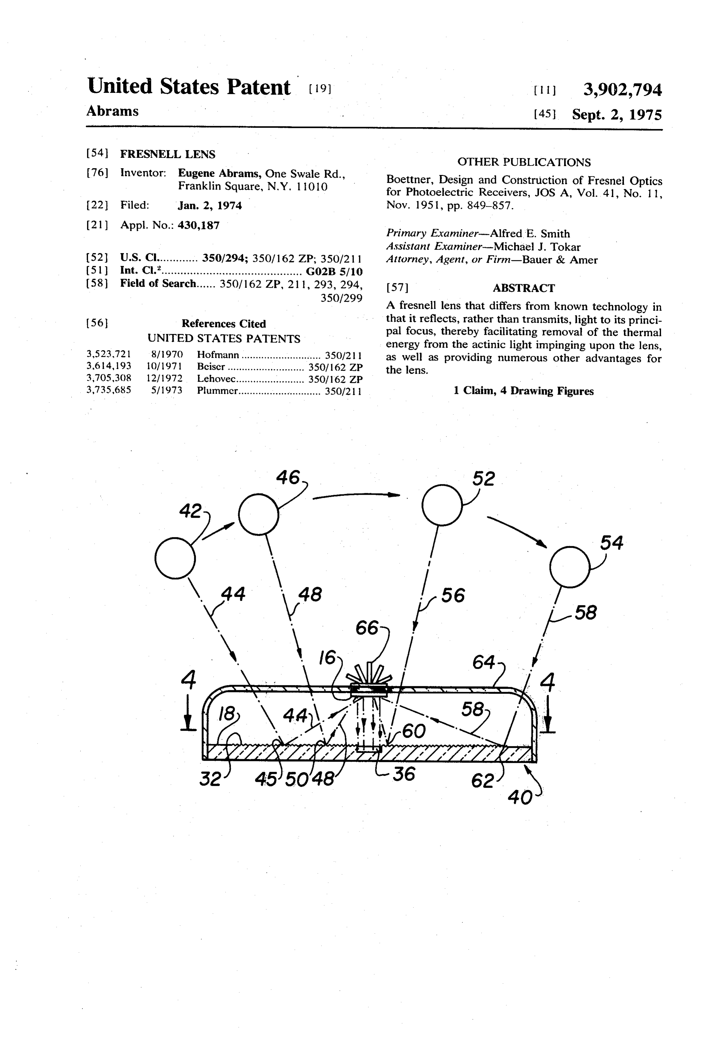
United States Patent (19) 11 3,902,794 Abrams (45) Sept. 2, 1975
54 FRESNELL LENS OTHER PUBLICATIONS (76) Inventor. Eugene Abrams, One Swale Rd., Boettner, Design and Construction of Fresnel Optics Franklin Square, N.Y. 1 OO for Photoelectric Receivers, JOS A, Vol. 41, No. 1 1, 22 Filed: Jan. 2, 1974 Nov. 1951, pp. 849-857.
(21) Appl. No.: 430,187 Primary Examiner-Alfred E. Smith Assistant Examiner-Michael J. Tokar (52) U.S. Cl............. 350/294; 350/162 ZP; 350/21 1 Attorney, Agent, or Firm-Bauer & Amer (5ll Int. Cl.’............................................ G02B 5/10 58 Field of Search...... 350/162 ZP, 21 1, 293, 294, 57 ABSTRACT 350/299 A fresnell lens that differs from known technology in
O that it reflects, rather than transmits, light to its princi 56 References Cited pal focus, thereby facilitating removal of the thermal UNITED STATES PATENTS energy from the actinic light impinging upon the lens, 3,523,721 8/1970 Hofmann ............................ 350/21 1 as well as providing numerous other advantages for 3,614, 193 l ()/ 1971 Beiser ......... ... 350/162 ZP the lens.
3,705.308 12/1972 Lehovec...... ... 350/162 ZP 3,735,685 5/1973 Plummer............................. 350/21 1 1 Claim, 4 Drawing Figures
Page 2
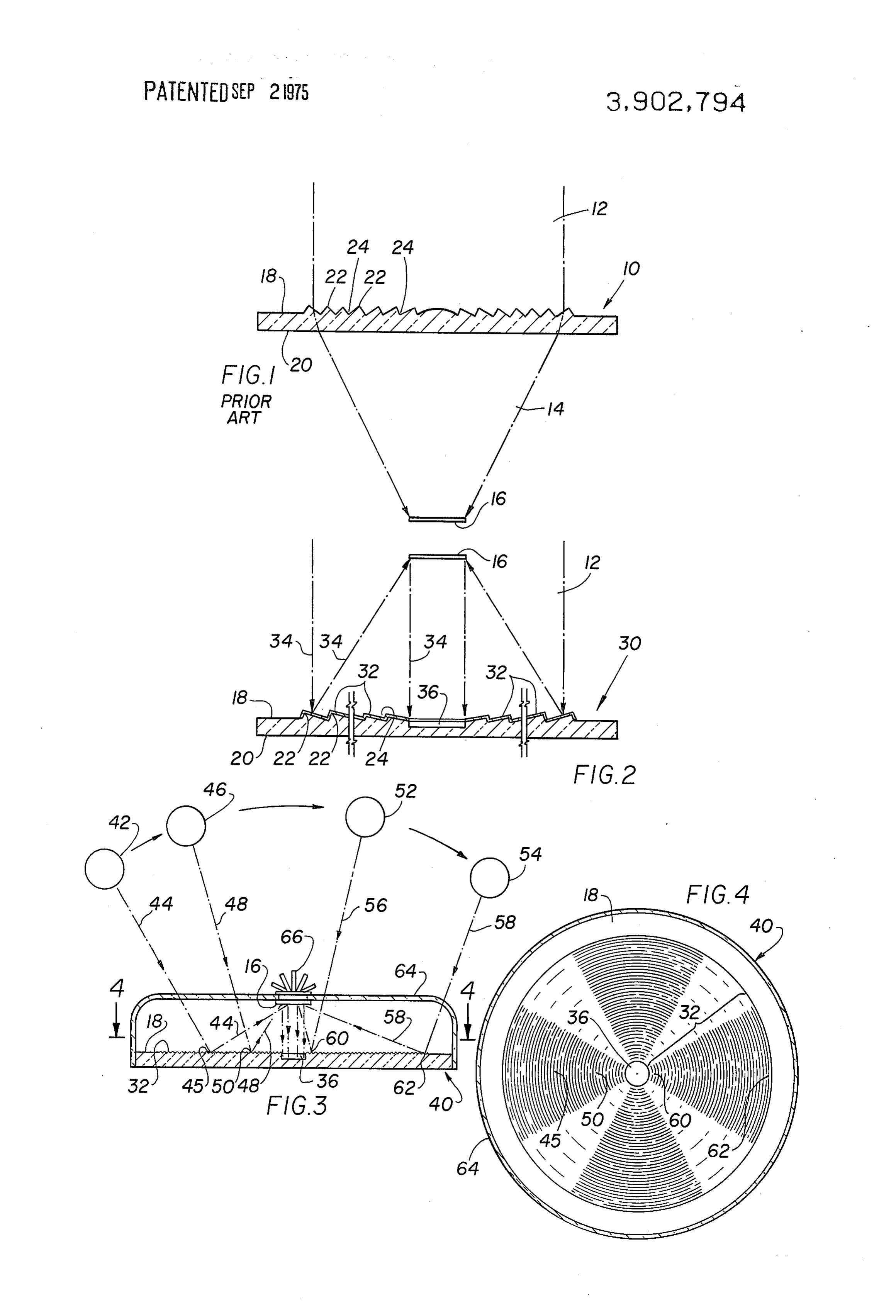
Drawing sheet — no readable text.
Page 3
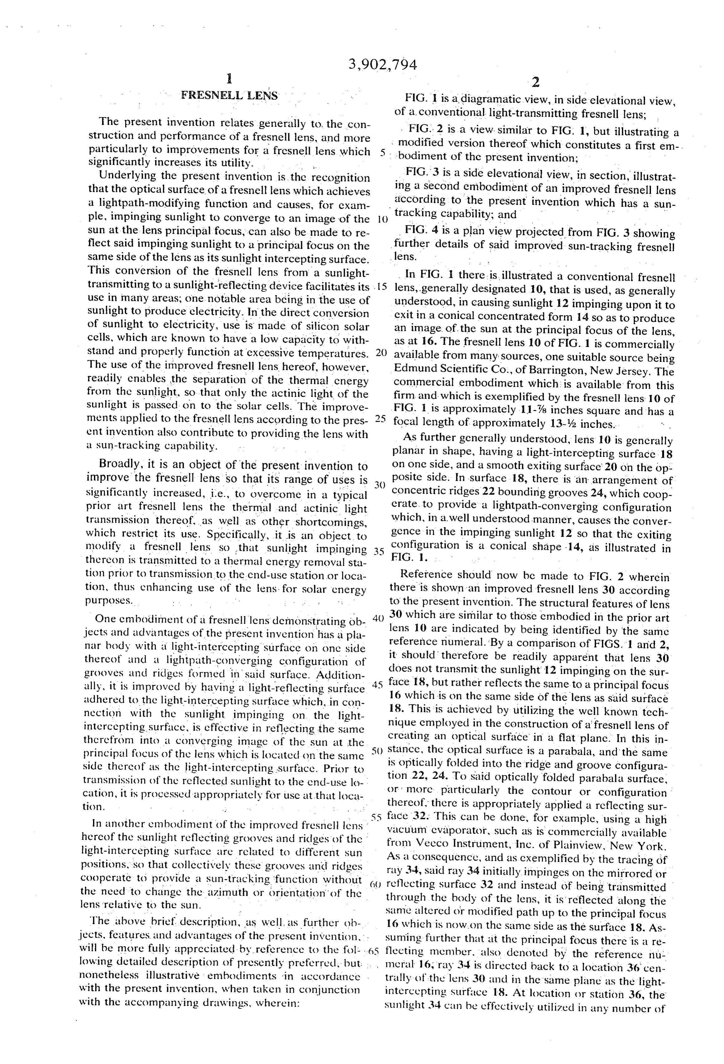
FRESNELL LENS FIG. 1 is a diagramatic view, in side elevational view, of a. conventional light-transmitting fresnell lens;
The present invention relates generally to, the con FIG. 2 is a view, similar to FIG. 1, but illustrating 2 struction and performance of a fresnell lens, and more modified version thereof which constitutes a first em particularly to improvements for a fresnell lens which 5. bodiment of the present invention; - significantly increases its utility.
Underlying the present invention is the recognition FIG. 3 is a side elevational view, in section, illustrat that the optical surface of a fresnell lens which achieves ing a second embodiment of an improved fresnell lens accordingcapability;
a lightpath-modifying function and causes, for exam tracking to the present and invention which has a sun ple, impinging sunlight to converge to an image of the () sun at the lens principal focus, can also be made to re FIG. 4 is a plan view projected from FIG. 3 showing flect said impinging sunlight to a principal focus on the further details of said improved sun-tracking fresnell same side of the lens as its sunlight intercepting surface. lens.
This conversion of the fresnell lens from a sunlight In FIG. there is illustrated a conventional fresnell transmitting to a sunlight-reflecting device facilitates its .
lens, generally designated 10, that is used, as generally use in many areas; one notable area being in the use of understood, in causing sunlight 12 impinging upon it to sunlight to produce electricity. In the direct conversion exit in a conical concentrated form 14 so as to produce of sunlight to electricity, use is made of silicon solar an image of the sun at the principal focus of the lens, cells, which are known to have a low capacity to with as at 16. The fresnell lens 10 of FIG. 1 is commercially stand and properly function at excessive temperatures. 20 available from many sources, one suitable source being The use of the improved fresnell lens hereof, however, Edmund Scientific Co., of Barrington, New Jersey. The readily enables the separation of the thermal energy commercial embodiment which is available from this from the sunlight, so that only the actinic light of the firm sunlight is passed on to the solar cells. The improve FIG. and 1 is which is exemplified by the fresnell lens 10 of approximately 11-78 inches square and has a ments applied to the fresnell lens according to the pres 2 5 focal length of approximately 13-y2 inches. ent invention also contribute to providing the lens with As further generally understood, lens 10 is generally a sun-tracking capability. planar in shape, having a light-intercepting surface 18 Broadly, it is an object of the present invention to on one side, and a smooth exiting surface 20 on the op improve the fresnell lens so that its range of uses is posite side. In surface 18, there is an arrangement of significantly increased, i.e., to overcome in a typical concentric ridges 22 bounding grooves 24, which coop prior art fresnell lens the thermal and actinic light erate, to provide a lightpath-converging configuration transmission thereof. as well as other shortcomings, which, in a well understood manner, causes the conver which restrict its use. Specifically, it is an object to gence in the impinging sunlight 12 so that the exiting modify a fresnell lens so that sunlight impinging configuration is a conical shape 14, as illustrated in thereon is transmitted to a thermal energy removal sta FIG. I.
tion prior to transmission to the cind-use station or loca Reference should now be made to FIG. 2 wherein tion, thus enhancing use of the lens for solar energy there is shown an improved fresnell lens 30 according
to the present invention. The structural features of lens
One embodiment of a fresnell lens demonstrating ob 30 which are similar to those embodied in the prior art jects and advantages of the present invention has a pla lens 10 are indicated by being identified by the same nar body with a light-intercepting surface on one side reference numeral. By a comparison of FIGS. 1 and 2, thereof and a lightpath-converging configuration of it should therefore be readily apparent that lens 30 does not transmit the sunlight 12 impinging on the sur grooves and ridges formed in said surface. Addition 45 face i8, but rather reflects the same to a principal focus ally, it is improved by having a light-reflecting surface adhered to the light-intercepting surface which, in con 16 which is on the same side of the lens as said surface nection with the sunlight impinging on the light 18. This is achieved by utilizing the well known tech intercepting surface, is effective in reflecting the same nique employed in the construction of a fresnell lens of therefrom into a converging image of the sun at the creating an optical surface in a flat plane. In this in stance, the optical surface is a parabala, and the same principal focus of the lens which is located on the same is optically folded into the ridge and groove configura side thereof as the light-intercepting surface. Prior to transmission of the reflected sunlight to the end-use lo tion 22, 24. To said optically folded parabala surface, cation, it is processed appropriately for use at that loca or more particularly the contour or configuration tion. thereof, there is appropriately applied a reflecting sur 55 face 32. This can be done, for example, using a high
In another embodiment of the improved fresnell lens vacuum evaporator, such as is commercially available hereof the sunlight reflecting grooves and ridges of the from Veeco Instrument, Inc. of Plainview, New York. light-intercepting surface are related to different Sun As a consequence, and as cxemplified by the tracing of positions, so that collectively these grooves and ridges ray 34, said ray 34 initially impinges on the mirrored or cooperate to provide a sun-tracking function without reflecting surface 32 and instead of being transmitted the need to change the azimuth or orientation of the through the body of the lens, it is reflected along the lens relative to the sun. same altered or modified path up to the principal focus The above brief description, as well, as further ob 16 which is now on the same side as the surface 18. As jects, features and advantages of the present invention, suming further that at the principal focus there is a re will be more fully appreciated by reference to the fol 6S flecting menber, also denoted by the reference nu lowing detailed description of presently preferred, but meral 16, ray 34 is directed back to a location 36 cen nonetheless illustrative embodiments in accordance trally of the lens 30 and in the same plane as the light with the present invention, when taken in conjunction intercepting Surface 18. At location or station 36, the with the accompanying drawings, wherein: Sunlight 34 can be effectively utilized in any number of
Page 4
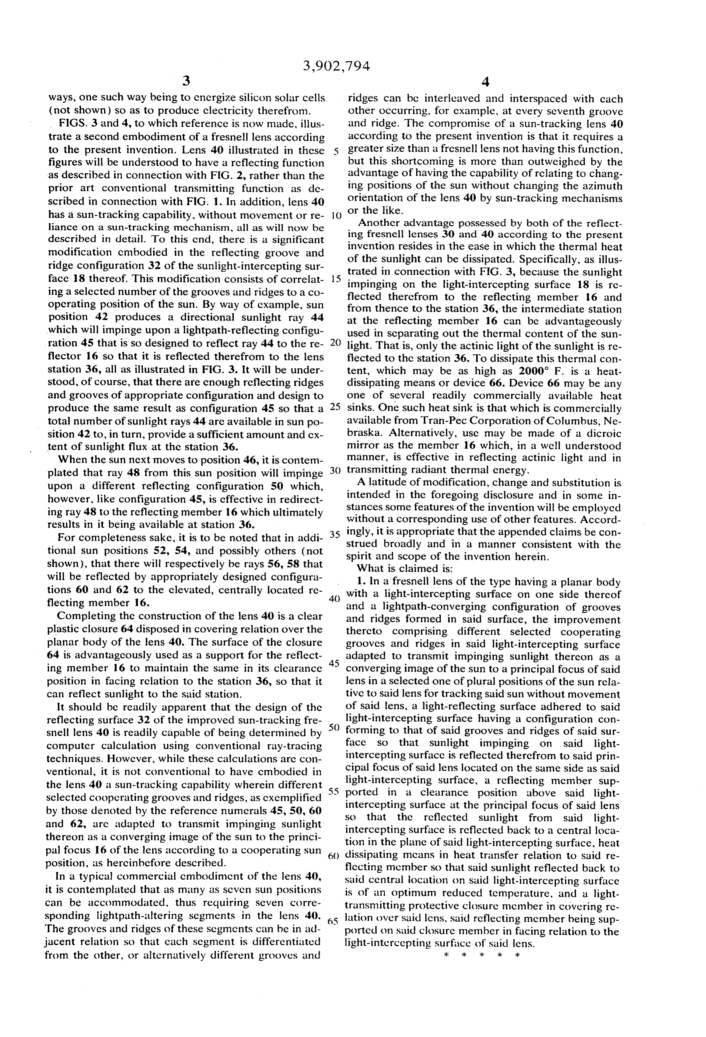
ways, one such way being to energize silicon solar cells ridges can bc interleaved and interspaced with each (not shown) so as to produce electricity therefrom. other occurring, for example, at every seventh groove FGS. 3 and 4, to which reference is now made, illus and ridge. The compromise of a sun-tracking lens 40 trate a second embodiment of a fresnell lens according according to the present invention is that it requires a to the present invention. Lens 40 illustrated in these 5 greater size than a fresnell lens not having this function, figures will be understood to have a reflecting function but this shortcoming is more than outweighed by the as described in connection with FIG. 2, rather than the advantage of having the capability of relating to chang prior art conventional transmitting function as de ing positions of the sun without changing the azimuth scribed in connection with FIG. 1. In addition, lens 40 orientation of the lens 40 by sun-tracking mechanisms has a sun-tracking capability, without movement or re () or the like.
liance on a sun-tracking mechanism, all as will now be Another advantage possessed by both of the reflect described in detail. To this cnd, there is a significant ing fresnell lenses 30 and 40 according to the present invention resides in the ease in which the thermal heat modification embodied in the reflecting groove and of the sunlight can be dissipated. Specifically, as illus ridge configuration 32 of the sunlight-intercepting sur trated in connection with FIG. 3, because the sunlight face 18 thereof. This modification consists of correlat impinging on the light-intercepting surface 18 is re ing a selected number of the grooves and ridges to a co flected therefrom to the reflecting member 16 and operating position of the sun. By way of cxample, sun from position 42 produces a directional sunlight ray 44 at thethence to the station 36, the intermediate station reflecting member 16 can be advantageously which will impinge upon a lightpath-reflecting configu used in separating out the thermal content of the sun ration 45 that is so designed to reflect ray 44 to the re 20 light. That is, only the actinic light of the sunlight is re flector 16 so that it is reflected therefrom to the lens flected to the station 36. To dissipate this thermal con station 36, all as illustrated in FIG. 3. It will be under tent, which may be as high as 2000 F. is a heat stood, of course, that there are enough reflecting ridges dissipating means or device 66. Device 66 may be any and grooves of appropriate configuration and design to one of several readily commercially available heat produce the same result as configuration 45 so that a sinks. One such heat sink is that which is commercially total number of sunlight rays 44 are available in sun po available from Tran-Pec Corporation of Columbus, Ne sition 42 to, in turn, provide a sufficient amount and cx braska. Alternatively, use may be made of a dicroic tent of sunlight flux at the station 36. mirror as the member 16 which, in a well understood When the sun next moves to position 46, it is contem manner, is effective in reflecting actinic light and in plated that ray 48 from this sun position will impinge 30 transmitting radiant thermal energy. upon a different reflecting configuration 50 which, A latitude of modification, change and substitution is however, like configuration 45, is effective in redirect intended in the foregoing disclosure and in some in ingray 48 to the reflecting member 16 which ultimately stances some features of the invention will be employed without a corresponding use of other features. Accord results in it being available at station 36. ingly, it is appropriate that the appended claims be con For completeness sake, it is to be noted that in addi 35 strued broadly and in a manner consistent with the tional sun positions 52, 54, and possibly others (not spirit and scope of the invention herein. shown), that there will respectively be rays 56, 58 that What is claimed is:
will be reflected by appropriately designed configura 1. In a fresnell lens of the type having a planar body tions 60 and 62 to the clevated, centrally located re 40 with a light-intercepting surface on one side thereof flecting member 16. and a lightpath-converging configuration of grooves Completing the construction of the lens 40 is a clear and ridges formed in said surface, the improvement plastic closure 64 disposed in covering relation over the thereto comprising different selected cooperating planar body of the lens 40. The surface of the closure grooves and ridges in said light-intercepting surface 64 is advantageously used as a support for the reflect 45 adapted to transmit impinging sunlight thereon as a ing member 16 to maintain the same in its clearance converging image of the sun to a principal focus of said position in facing relation to the station 36, so that it lens in a selected one of plural positions of the sun rcia can reflect sunlight to the said station. tive to said lens for tracking said sun without movement It should be readily apparent that the design of the of said lens, a light-reflecting surface adhered to said reflecting surface 32 of the improved sun-tracking fre light-intercepting surface having a configuration con snell lens 40 is readily capable of being determined by 50. forming to that of said grooves and ridges of said sur computer calculation using conventional ray-tracing face so that sunlight impinging on said light techniques. However, while these calculations are con cipal intercepting surface is reflected therefrom to said prin ventional, it is not conventional to have embodied in focus of said lens located on the same side as said light-intercepting surface, a reflecting member sup the lens 40 a sun-tracking capability wherein different 5 5 ported sclected cooperating grooves and ridges, as exemplified in a clearance position above said light by those denoted by the reference numerals 45, 50, 60 so that thesurface intercepting at the principal focus of said lens reflected sunlight from said light and 62, are adapted to transmit impinging sunlight intercepting surface is reflected back to a central loca thereon as a converging image of the sun to the princi tion in the plane of said light-intercepting pal focus 16 of the lens according to a cooperating sun dissipating mcans in heat transfer relationsurface, heat to said re position, as hereinbefore described. flecting member so that said sunlight reflected back to In a typical commercial cmbodiment of the lens 40, said central location on said light-intercepting surface it is contemplated that as many as seven sun positions is of an optimum reduced temperature, and a light can be accommodated, thus requiring seven corre transmitting protective closure member in covering re sponding lightpath-altering segments in the lens 40. 65 lation over said lens, said reflecting member being sup The grooves and ridges of these segments can be in ad ported on said closure member in facing relation to the jacent relation so that cach segment is differentiated light-intercepting surface of said lens. from the other, or alternatively different grooves and sk sk sk ck ck
Provenance
- Collection
- Cited prior art
- Original PDF
- patentimages.storage.googleapis.com →
- Filed
- 1974-01-02
- Pages
- 4
- Method
- pdftotext (the PDF's own text layer) + pdftoppm 300dpi page scans
- Source
- Google Patents bibliographic record
- Granted
- 1975-09-02
- Inventors
- Eugene Abrams
- Transcribed from
- patentimages.storage.googleapis.com →