patent · US3844270
Energy conversion system
29 October 1974
Page 1 — bibliographic record
United States Patent 19 [11] 3,844,270 Black (45) Oct. 29, 1974
54 ENERGY CONVERSION SYSTEM 3,525,325 8/1970 Perl................................. 431/25 X 3,538,908 11/1970 Weil.... ... 126/39 J 76) inventor: Robert B. Black, 2925 Denver St., 3,547,592 12/1970 Glado et al. ... 126/91 A Corpus Christi,Tex. 3,669,079 6/1972 Black.............................. 122/136 R 22 Filed: Oct. 26, 1971 Primary Examiner-William E. Wayner (21) Appl. No.: 192,262 Assistant Examiner-Peter D. Ferguson Related U.S. Application Data Attorney, Agent, or Firm-Synnestvedt & Lechner 63 Continuation-in-part of Ser. No. 61,775, Aug. 6, 1970, Pat. No. 3,669,079. 57 ABSTRACT 52 U.S. Cl........... 126/110 R, 48/180 C, 126/39 J, A system for the transmission and conversion of the 126/91 A, 431/215, 431/346, 431/353 potential energy of hydrocarbon fuels to available I51) int. Cl............................................... F24h 3/02 heat, power and light. The system is particularly 58) Field of Search............... 126/39 J, 39 H, 91 A; adapted for use with natural gas, artificial gases or any 431/1 16, 215, 353, 346; 122/24; 431/210; of the LPG fuels such as propane, butane, etc. Ac 48/180 C, 180 R cording to the system of the invention, the fuel gas is mixed with air preferably in the amount providing the 56) References Cited stoichiometric ratio of oxygen and is stored under UNITED STATES PATENTS pressure and ultimately transmitted to burner ele ments which are hermetically sealed except for the 1,017,180 2/1912 Shearman et al................... 4311210 inlet and discharge ports, such as tubes, power 1,039,297 9/1912 Kunkel................................ 4311210 sources, such as captive and free piston devices and 1,264,005 4/1918 Buchanan......................... 126/91 A gas turbines and light sources. The system includes 1488,238 3/1929 Good................................ 126/91 A special forms of equipment for mixing the gas and air 1993,748 3/1935 Noack................................... 122124 2,362,972 l l 1944 Browaback........................ 126/39 J and special forms of equipment for establishing and 2,602,440 7/1952 Corns................................ 12619. A controlling the combustion processes. 2,643,944 6/1953 Malir, Jr........................... 481180 R 22 Claims, 12 Drawing Figures
Page 2
Drawing sheet — no readable text.
Page 3
Drawing sheet — no readable text.
Page 4
Drawing sheet — no readable text.
Page 5
Drawing sheet — no readable text.
Page 6
Drawing sheet — no readable text.
Page 7
ENERGY CONVERSION SYSTEM which receives the fuel-air mixture and the other end of which discharges the products of combustion. The
The present application is a continuation-in-part of system further includes numerous features relating to my application Ser. No. 61,775 filed Aug. 6, 1970, and control or regulation of the burning or combustion ac issued as U.S. Pat. No. 3,669,079 on June 13, 1972. tion, all of which will be described fully hereinafter. Although certain features of the system of the pres It is a major general objective of the invention to pro ent invention are applicable for a wide variety of pur vide a heating system, for instance for a kitchen range, poses, including power production and lighting, most which system retains most of the economy of the prior aspects of the invention are of especial utility in the known open flame gas burners and also offers the prin production of heat, the burner element in which the 10 cipal advantages of the prior known electrical resis fuel is burned being adapted for heat transfer to solid, tance heating elements, while at the same time elimi liquid or gaseous materials. Because of the special nating the disadvantages of both of those prior types of adaptability of the system of the invention for heating heating systems.
purposes, most of the following description is related to Thus, the present invention contemplates a heating that general use of the system. 15 system of much lower operating cost than with electric
BACKGROUND
systems and in which much faster heating may be achieved than with either electric or open flame gas
Heating systems and elements of a wide variety of burners. The noxious fumes and soot which are charac types are already known. For domestic and industrial 20 teristic of open flame burners are eliminated, and the heating purposes, most of the systems in wide usage ei combustion products are not pollutants. The burner el ther employ open flame gas burners or electrical resis ement does not consume oxygen in the work area. Ex tance heating elements. For example, kitchen ranges plosion hazard is eliminated. Open pilot lights and are customarily provided either with a group of open matches are not needed. The system of the present in flame gas burners, or with a group of flat coil electrical 25 vention, however, retains the economy of gas use. In heating elements. comparison with the open flame gas burners, the sys Open flame gas burners have certain advantages in tem of the present invention is characterized by a much cluding the fact that the burner may readily be incre higher heat transfer rate or thermal efficiency. mentally adjusted to the flame or heat desired, but To illustrate the effectiveness and rapidity of heating, open flame burners have serious disadvantages includ 30 a comparative test was made in which a quart of room ing the release of noxious fumes and the tendency to temperature water was heated to a full boil on a con accumulate soot in surrounding areas. Open flame ventional open flame gas burner, a conventional elec burners also present an explosion hazard. In addition, trical resistance element, and on a pancake coil tubular they tend to produce excessive heat in the working area heating element conforming with the system of the and result also in burning up of the oxygen in the work 35 present invention. The burners were all turned on until ing area. Still further the open flame burners are disad their maximum heat output was reached before the test vantageous as they require either matches or a con was begun. In the case of the electrical heater the time stantly burning pilot light for ignition. Moreover, in required to reach a full boil was 11% minutes. In the spite of the fact that the common gas supply systems case of the open flame gas burner, the time was 10 min operate at a pressure of only a minor fraction of 1 psi, 40 utes, and in the case of the tubular heating element de any leak in the system is a potential fire hazard because scribed herein, the time was 4 minutes. The same kettle the leakage gas may readily be ignited in the presence was used in each test so as to eliminate possible vari of the oxygen in the ambient air. ables which might result from using different kettles. On the other hand the common electrical resistance Various other advantages and operational character heating elements are advantageous in that they elimi 45 istics will be described hereinafter following the de nate some of the deficiencies just referred to of open scription of the system as illustrated in the accompany flame gas burners. However, the electrical heating re ing drawings.
sistance elements are in general more expensive to op BRIEF DESCRIPTION OF DRAWINGS erate than those operating with gas, this differential being very pronounced in certain areas of the United In the drawings:
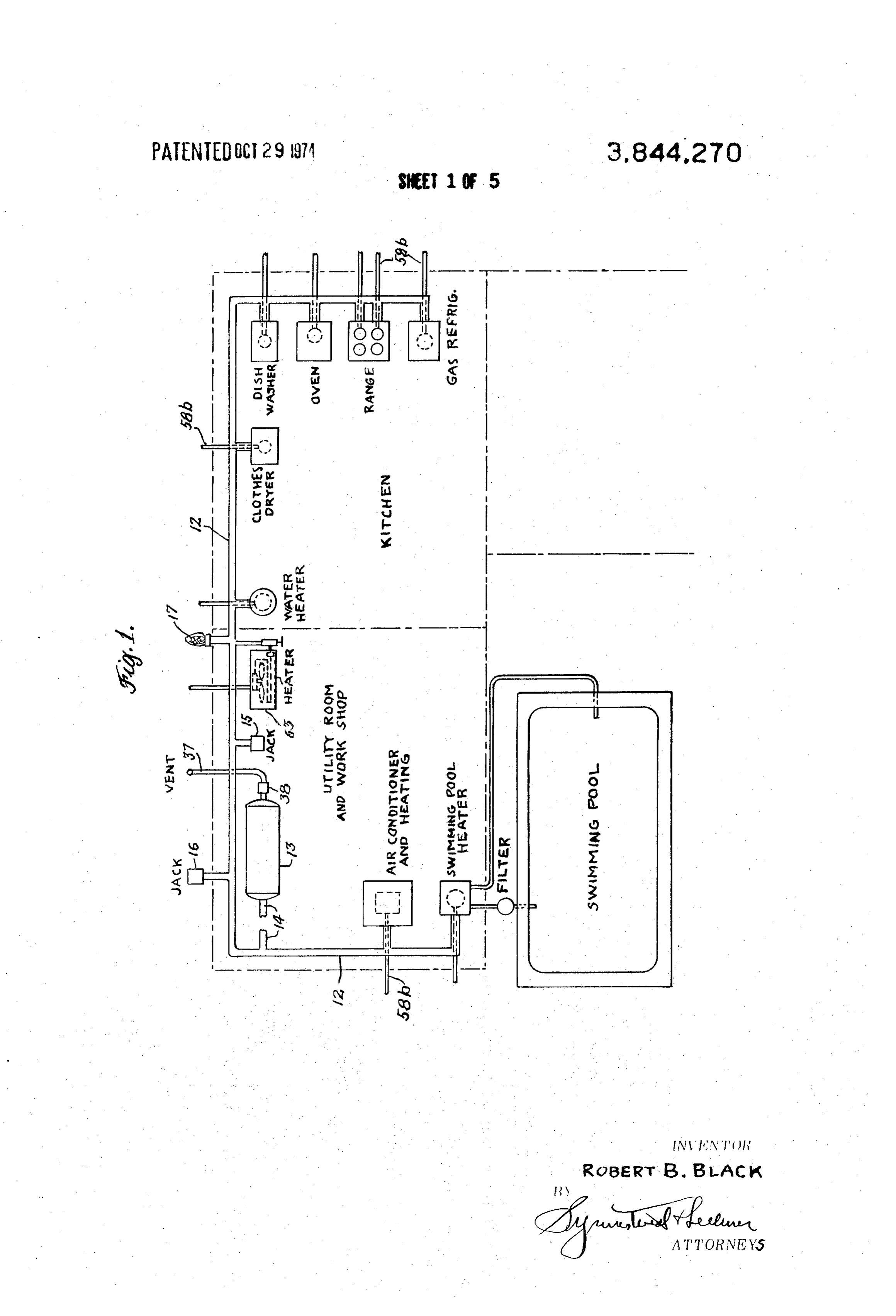
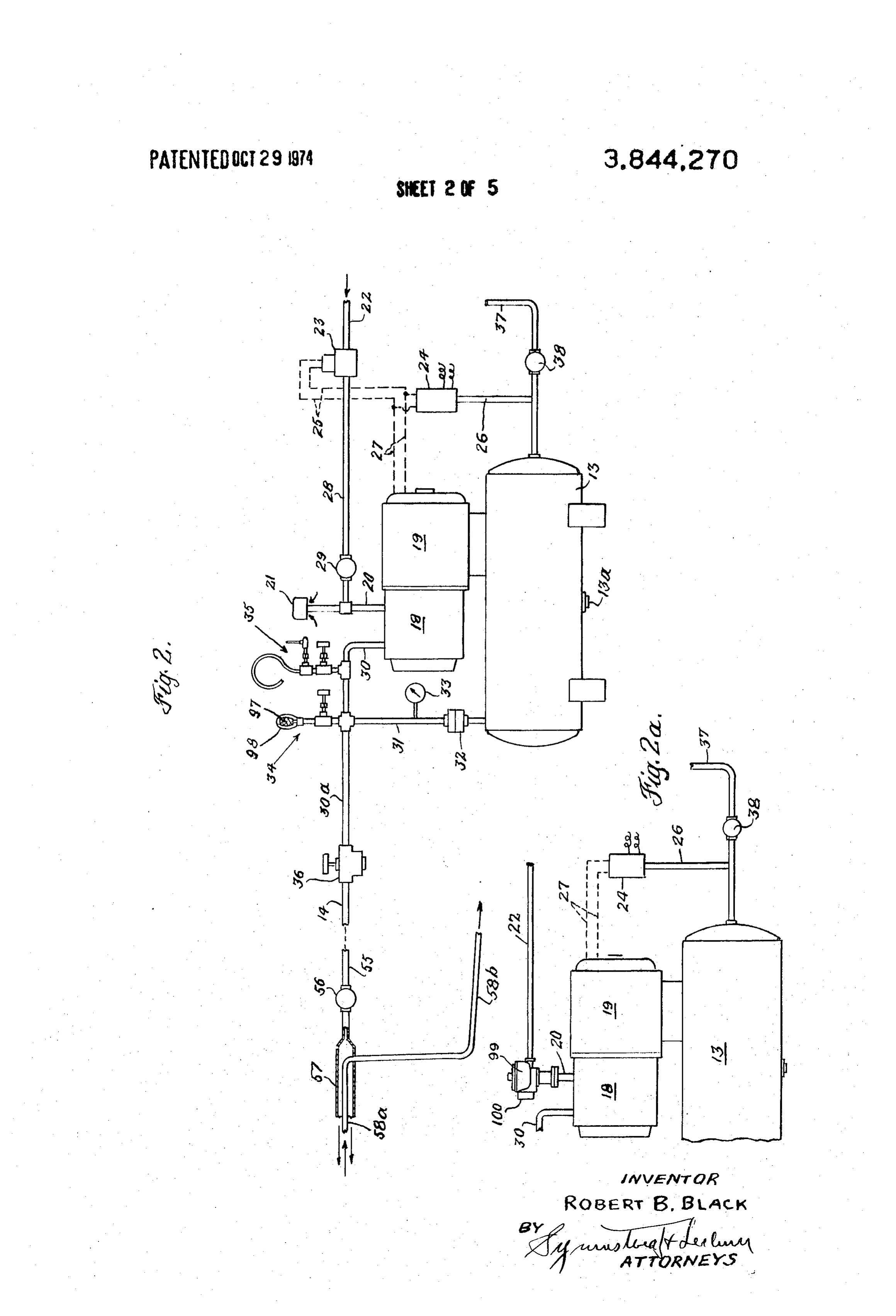
States and many other countries, notably those areas 50 FIG. 1 is a schematic layout of some of the principal which are relatively accessible to sources of natural gas components of an energy conversion system according in which one cent will buy about four times as many to the present invention as applied to various appli Btu with gas as with electricity. ances commonly used in a home; Both electric and open flame gas burners also have 55 FIG. 2 is a schematic view of the major components the disadvantage that the heating rate with such burn of one form of gas and air mixing and storing equip ers is relatively low. ment according to the invention, this system being ap THE SYSTEM OF THE INVENTION AND plicable to an installation of the kind diagrammed in
OBJECTIVES THEREOF
60 FIG. 2a is a fragmentary view of certain parts of the
Briefly described, the system of the present invention system of FIG. 2 but illustrating the use of a carburetor as applied for the purposes of heating, for instance in for mixing the gas and air;
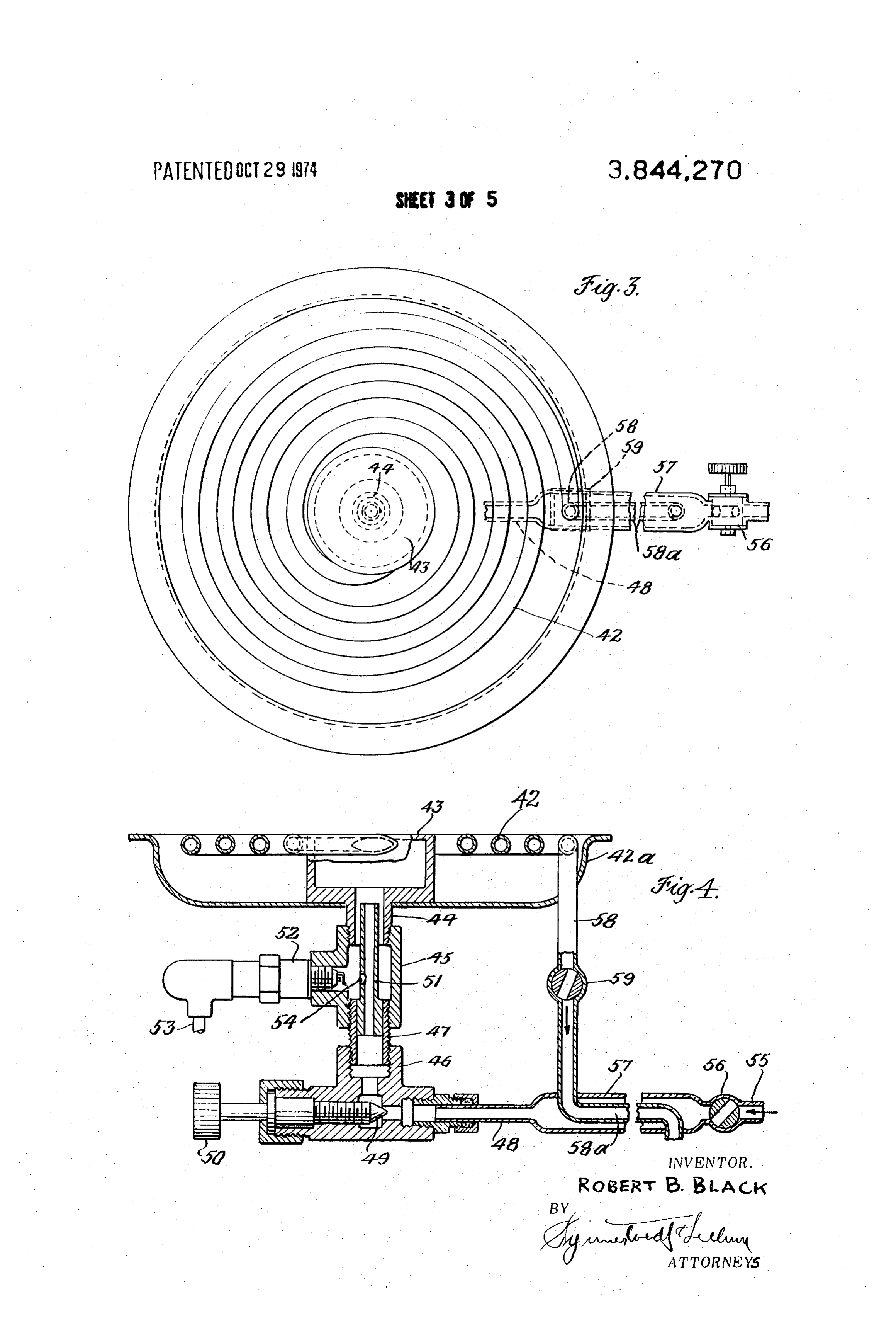
a kitchen range burner, preferably comprises a means FIG. 3 is a plan view of a heating element and associ for mixing fuel gas with air in the correct ratio and for ated parts adapted for use as a heater on a kitchen building up a substantial pressure in the mixture, to 65 range;
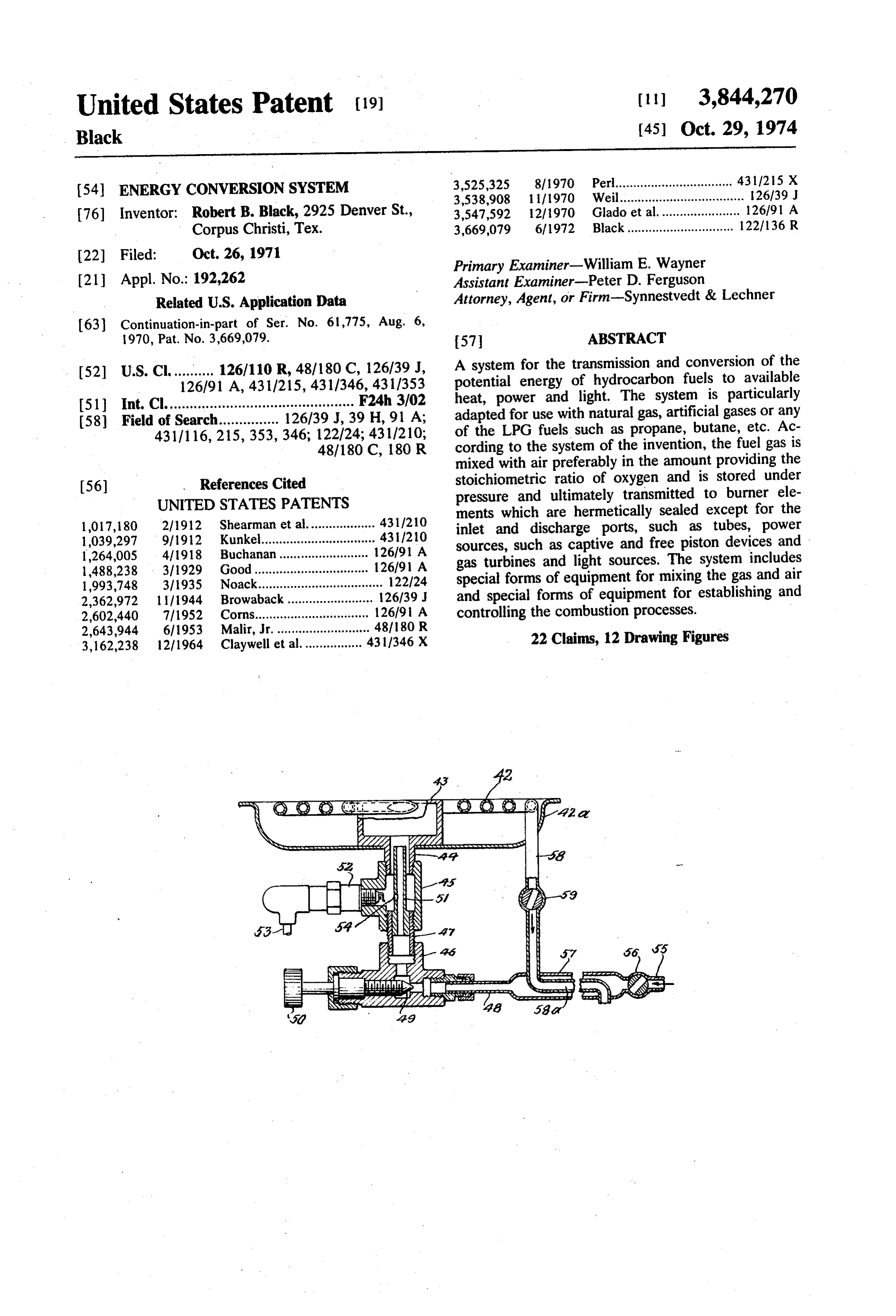
gether with a storage means for a supply of the pressur FIG. 4 is a sectional view of the heating element ized gas-air mixture. A burner is provided, for example shown in FIG. 3 and associated inlet and discharge in the form of a flat spiral coil of a tube one end of equipment;
Page 8
FIG. S is a somewhat diagrammatic horizontal sec As shown in FIG. 1 the supply line 12 is also indi tional view through a space heater constructed for use cated as connected with a gas lamp, comprising a man in accordance with the system of the present invention; tle 17 which may serve for outdoor lighting. Turning now to the equipment shown in FIG. 2, it is
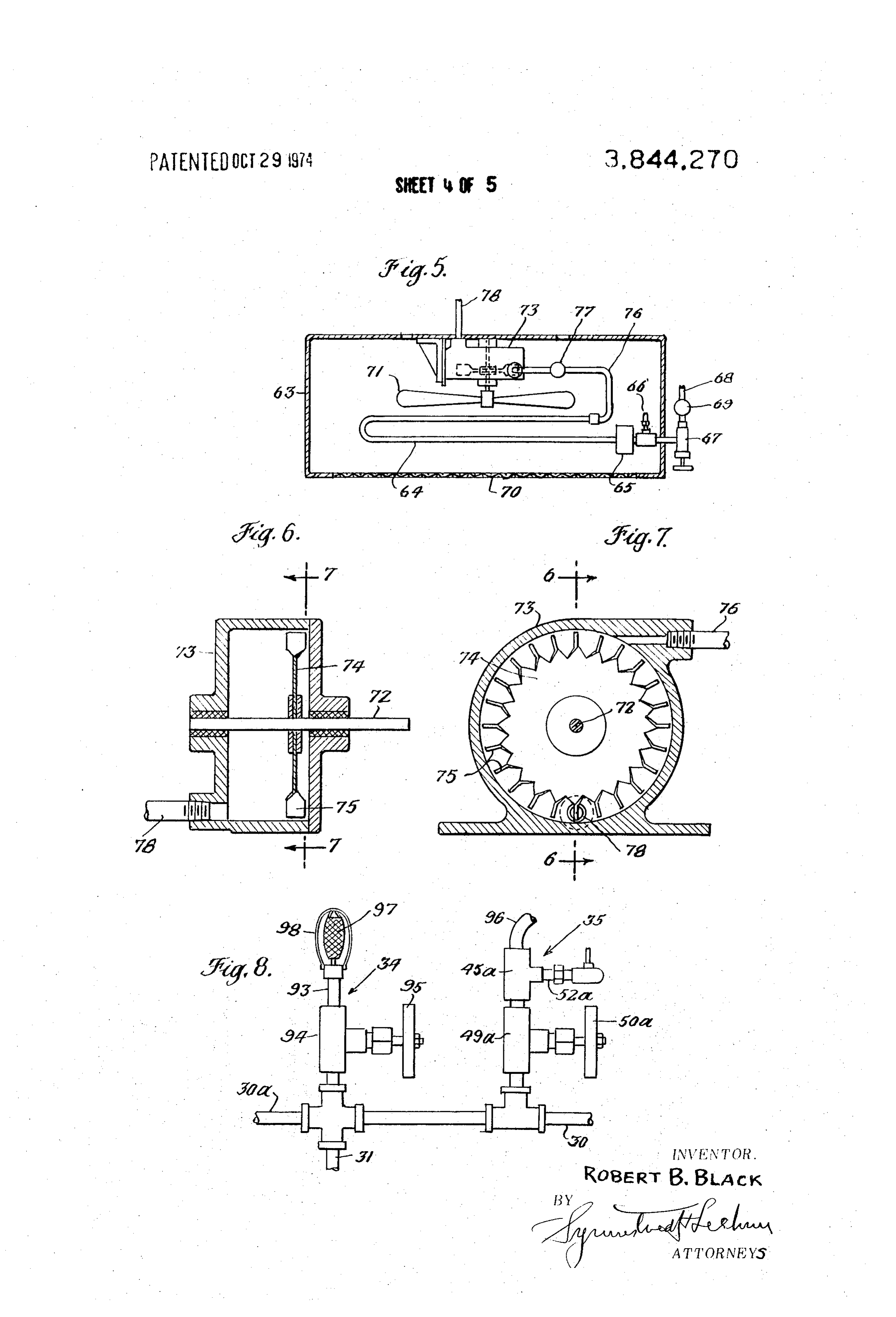
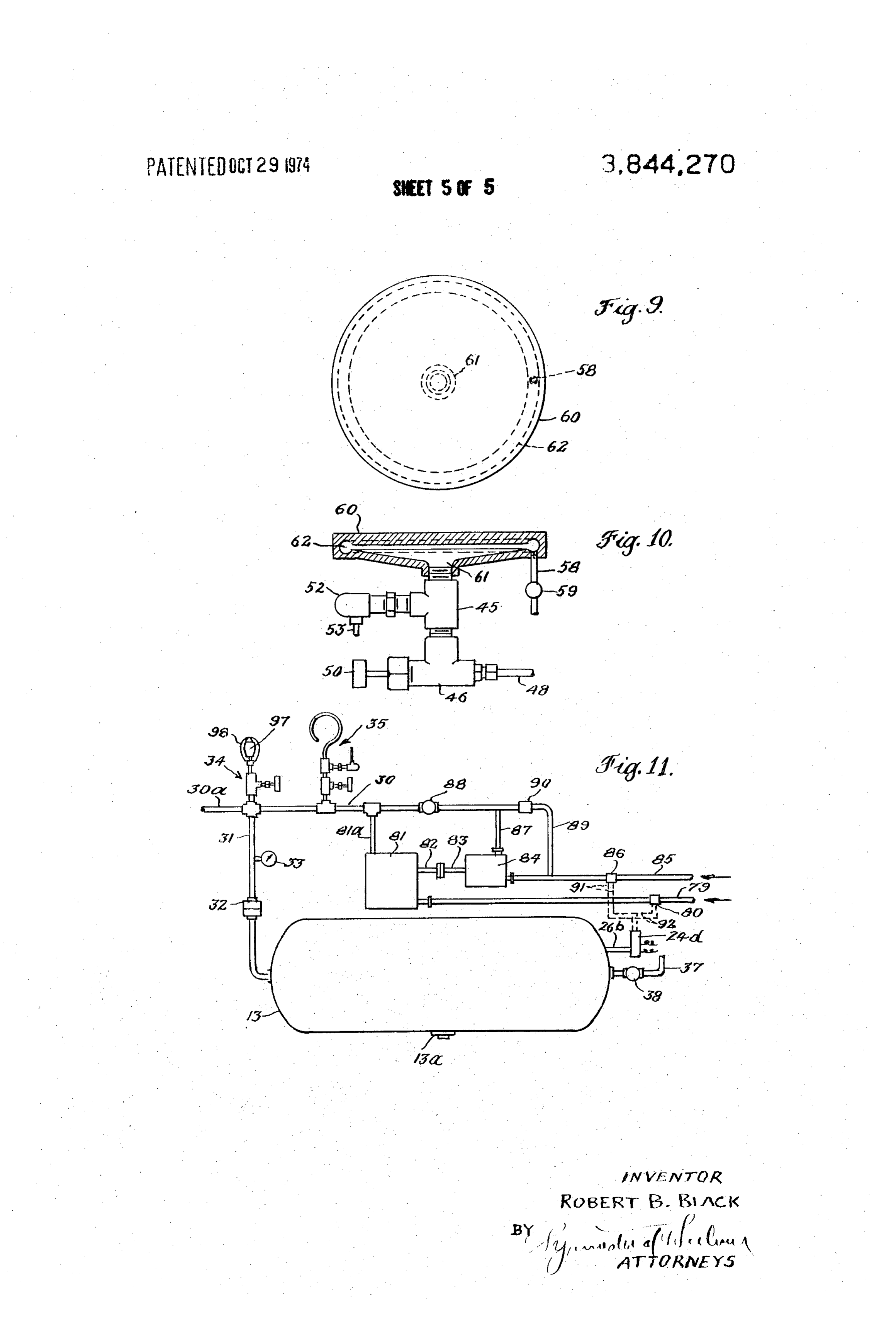
FIG. 6 is an axial sectional view through a turbine to be understood that this represents one form of adapted to be employed to drive a fan, for instance in equipment which may be employed for charging the a space heater such as illustrated in FIG. 5, FIG. 6 storage tank 13 with the pressurized gas-air mixture. being taken as indicated by the section line 6-6 on As shown in FIG. 2 a pressurizer or compressor 18 FIG. 7; having a driving motor 19 is mounted upon the tank 13 FIG. 7 is a sectional view of the turbine of FIG. 6 the pressurizer having an intake line 20 with an air in taken as indicated by the line 7-7 on FIG. 6; take associated with the filter and silencer indicated at FIG. 8 is a fragmentary enlarged view illustrating cer tain portions of the equipment shown in FIG. 2, espe 21. The gas supply line is shown at 22, this line being cially the gas-air ratio testing equipment preferably em operated with provided a master control valve 23 adapted to be by the pressure response of switch device 24
through the electrical circuit 25. The pipe 26 serves to
FIG. 9 is a plan view of an alternative non-tubular, communicate the pressure in the storage tank 13 to the flat form of burner element adapted for use in a kitchen pressure switch 24 and provide for the opening and range;
FIG. 10 is a sectional view of the burner element of closing of the valve 23 in accordance with the pressure FIG.9 and showing also in outline certain of the appur and in the supply tank. Typical pressure values for opening tenant equipment to be used in connection with such hereafter. closing the switch will be referred to more fully a burner element, The switch 24 also has a circuit 27 for oper and ating the motor 19 which drives the pressurizer 18. FIG. 11 is a diagrammatic view illustrating an alter When the valve 23 is open, gas will pass through the native arrangement for mixing, pressurizing and storing 25 pipe 28 through the valve 29 and into the inlet line 20 the gas and air in stoichiometric ratio, this alternative comprisestoa needle extended the pressurizer 18. The valve 29 desirably control valve for purposes to be ex arrangement being adapted for use, for instance in an plained more fully hereinafter.
installation such as shown in FIG. 1 in place of the The outlet from the pressurizer 18 is indicated at 30 equipment of FIG. 2.
30 and this line is extended for connection with pipe 31
DETAILED DESCRIPTION OF THE which delivers into the storage tank 13. A flame arres EMBODIMENTS ILLUSTRATED tor 32 is introduced in the line 31 and this line 3 also desirably has a pressure gauge 33 for indicating the
Although the system of the invention is adapted for pressure use in a wide variety of situations or installations, in in the supply tank. The flame arrestor 32 may cluding industrial plants, motels and residences, for 35 be of any desired known type, including a simple pipe purposes of illustration herein, the system is shown and union or fitting stuffed with stainless steel wool. For the purpose of testing and establishing the de described as employed in a residence or home.
In FIG. 1 a portion of a home is indicated in plan by sired gas-air ratio, the system preferably includes two dot and dash lines, including a kitchen, a utility room 40 devices one of which is indicated generally at 34 and and an adjoining outdoor swimming pool. Various ap the other is indicated generally at 35, these devices pliances with which the system of the invention may be being shown in greater detail in FIG. 8 and being de employed are shown in the kitchen, including a water scribed more fully hereinafter in connection with the description of the operation of the system.
heater, a clothes dryer, a dishwasher, a kitchen range and a kitchen oven, and a refrigerator of the type The pipe 30 is not only connected with the storage adapted for operation by gas heating. In the utility 45 tank 13 (through the pipe 31), but is also extended as room there are also shown certain appliances adapted indicated at 30a for delivery of the stored pressurized to be used with the system of the present invention, in gas-air mixture to the various appliances or other cluding a space heater, a unit adapted for alternative points of use. As shown in FIG. 2, this supply line 30a use for air conditioning and for heating, and a heater desirably includes an adjustable pressure regulator 36, for water used in the swimming pool. ensuring uniformity of pressure in the connection 14 All of the appliances mentioned in both the kitchen (see also FIG. 1) on the downstream side of the regula and utility room are adapted to be fed with the pressur tor, i.e., in the supply line 12 and in various connec ized gas-air mixture through the supply line indicated tions which would be extended from the supply line to at 12. This supply line receives the pressurized gas-air 55 the various appliances and devices to be operated. At mixture from a storage tank or reservoir 13 through the the left end of FIG. 2 there is fragmentarily shown por line indicated at 41. tions of one such appliance to which the pressurized The system of the invention also desirably includes mixture is being fed.
one or more jacks such as indicated at 15 and 16 pro The supply tank is also desirably provided with a vent viding for the "plug-in' of gas operated appliances, for 60 pipe 37 (see also FIG. 1) which is extended to a point example a gas operated torch or soldering iron or a de exterior of the house and through which air may be dis vice embodying a motor of some type operated by com charged from the storage tank 13 when the tank is ini bustion of the gas. As will be seen from FIG. 1 one of tially charged with the gas-air mixture, as will be fur these jacks (15) is located in the utility room where it ther explained. The vent is provided with a shut off may serve for attachment of devices to be used in a valve 38.
work shop, and the other jack (16) is located outside 65 The storage tank 13 has a discharge valve device 13a of the house to facilitate use of appliances in the sur in the bottom, of a known type adapted to automati rounding area. cally discharge any condensate or accumulated liquid,
Page 9
without, however, discharging the stored pressurized to a point exterior of the building in which the appli gas-air mixture. ance is located in order to discharge the products of Turning now to FIGS. 3 and 4, the burner element combustion outside of the building. Such discharge there shown comprises a tube 42, made for instance of pipes 58b are shown in FIG. 1 for various of the appli a stainless steel or high nickel content metal, such as 5 ances there illustrated. The extension of the exhaust or the metal known under the Trade Mark Inconel. This discharge connection downwardly (either vertically or tube is spirally wound in a flat coil and has its inner or at an incline) is of importance because water comprises inlet end connected with a small combustion chamber a component of the products of combustion and gravity formed within the central fitting 43. A polished reflec will thereby discharge such water and avoid trapping or tor 42a is desirably located below the tubular burner () clogging of the outlet line.
element 42 in order to reflect heat upwardly and to in the burner arrangement of FIGS. 3 and 4 it is to serve also as a drip pan. be noted that the output choke valve 59 is desirably The fitting 43 has a threaded nipple 44 cooperating employed only for "factory adjustment' and does not with the T-fitting 45 which is connected in turn with the constitute an everyday control in the hands of the user. casing 46 of a valve structure by means of the threaded 15 Similarly, the needle valve 49 is intended for only fac tube 47. The casing 46 is also connected to the supply tory or occasional adjustment, the normal manual con line 48 and the communication from the supply line to trol for the burner being provided by the adjustable the tube 47 and thus to the burner element is regulated plug 56 which is preferably located on the upstream or controlled by means of a needle valve 49 having an side of the heat exchanger 57-58a.
external operating handle 50 providing for adjustment Attention is now called to the fact that in the supply as will further be described. The gas-air mixture which system as illustrated in FIG. 2 the flame arrestor 32 is passes the needle valve 49 enters the tube 47 and then so located as to preclude "flame-back' either from any passes upwardly through the inner tube 51 mounted of the individual appliances fed by the system or from within the T-fitting 45 and is delivered from the upper 25 the compressor-motor unit. However even without end of the tube 51 into the combustion chamber at the such a flame arrestor, the arrangement of spark plug center of the burner element. It will be noted that there ignition and needle control valve (52 and 49) shown in is an annular space between the inner tube 51 and the FIG. 4 is also effective in preventing combustion at any threaded nipple 44 communicating both with the com point except beyond the delivery end of the inner feed bustion chamber at its upper end and also with the inte 30 tube 51 shown in FIG. 4. As will be explained hereinaf. rior of the T-fitting 45. The T-fitting 45 also receives an ter, it is contemplated to have a pressure drop across electrical igniter such as the spark plug 52, this device needle valve 49, and this also serves to prevent flame being supplied with current by a cable indicated at 53. back. The amount of pressure drop across the needle I prefer to provide some apertures such as indicated at valve 49 may readily be controlled by adjustment of the 54 in the inner tube 51 in the region of the spark plug 35 needle valve and of the choke 59 as is explained herein 52. I have found that this needle valve and spark plug after.
system closely connected with the inlet end of the An alternative form of range burner is shown in burner results in reliable ignition and stable operation FIGS. 9 and 10. Instead of employing the spirally without tendency for the combustion to creep back wound tubular burner element of FIG. 4, the embodi into the T-fitting 45, which is desirable in order to 40 ment of FIG. 9 employs a circular plate-like element avoid excessive heating of the spark plug and also of 60, preferably formed of a metal having a low coeffi the needle control valve, cient of thermal expansion and high heat resistance. In a typical installation the electrical igniter 52 may The element 60 has a central boss 61 on the underside conveniently be left in operation throughout the use of providing a combustion chamber which communicates the burner. with a thin circular cavity through which the combus The gas-air mixture is supplied to the equipment 45 tion products travel radially outwardly into the periph shown in FIGS. 3 and 4 through the connection 55 hav eral groove 62 which is provided with a discharge pipe ing a manually adjustable plug valve 56 delivering the 58 as above described for discharge of the products of gas-air mixture into an enlarged tube 57 which in turn combustion. From FIG. 10 it will be seen that this is connected with the pipe 48. The enlarged tube 57 50 burner is also provided with the electrical igniter 52 serves as a part of a heat exchange device by means of and needle control valve having a handle 50 and valve which the incoming gas-air mixture is preheated before casing 46, as in FIG. 4.
reaching the needle valve 49. This preheating is ef From FIGS. 9 and 10 it will be seen that the combus fected by utilizing heat from the products of combus tion or burner element need not necessarily be in tubu tion delivered from the discharge end of the heater ele 55 lar form. Such burner elements may in fact be of a wide ment 42. For this purpose the discharge end of the variety of shapes and sizes, depending upon the uses heater element is connected with a pipe 58 having an and purposes to be served. Tubular elements in U adjustable choke valve 59 therein, the pipe 58 having shape or hairpin configuration may be used for various a portion 58a extended through the enlarged gas supply purposes such as for air or water heating. In general, pipe 57 so that the heat of the products of combustion 60 however, it is contemplated that the electrical igniter is transferred to the incoming gas-air mixture. This heat and needle valve control arrangements as described exchange arrangement and also the valve 56 and supply above in connection with FIG. 4 should be employed, line 55 are indicated at the left end of FIG. 2 in order and should be associated with the burner element as to illustrate one appliance as coupled with the gas-air closely as practical.
supply system shown in FIG. 2. From FIG. 2 it will fur 65 The appliance illustrated in FIGS. 5, 6 and 7 com ther be seen that the discharge pipe 58a for the burner prises a space heater of a type adapted for use in shops, element is extended downwardly and has a downwardly garages, etc. As seen in FIG. 5 this heater comprises a inclined terminal portion 58b adapted to be extended casing 63 in which is mounted a heater element such as
Page 10
the U-shaped tubular element 64 the inlet end of which with a vent pipe 37 having a control valve 38 therein. is provided with a combustion chamber indicated at 65, a spark ignition 66 and a needle control valve 67, pref. In the embodiment of FIG. 11 it is further contem erably of the general type described above with refer plated that the valves 80 and 86 be responsive to the ence to FIG. 4. Here the gas-air supply line 68 is further pressure in the storage tank 13, and for this purpose a provided with a manual control valve 69 which serves pressure responsive switch 24d is provided with a con as the normal On-Off or adjustment valve. The heater nection 26b communicating with the interior of the casing is provided with a grill or grating 70 at the front, storage tank 13. The electrical connections 91 and 92 and behind the heater element 64 a fan 71 is mounted, serve to connect the pressure responsive switch 24d this fan being secured to a shaft 72 (see FIGS. 6 and 7) O with the gas valve 86 and the air valve 80. It is contem mounted in the casing 73 of a low power turbine com plated that the system of FIG. 11 by adjusted so that the prising a rotor 74 having peripheral buckets or blades valves 80 and 86 will be opened at a storage tank pres 75. The gas discharge pipe 76 which is connected with sure of for example 50 psi and that the valve 80 and 86 the discharge port or end of the tube 64 is provided be closed upon attaining a predetermined higher pres with a choke valve 77 of the kind described above in 5 sure, for instance 60 psi. It will be understood that with connection with FIG. 4 and this discharge pipe 76 is a system as shown in FIG. 11, the operating air pres connected with a passage entering the casing 73 tan sure, typically about 90-100 psi, will of course drop gentially with reference to the path of movement of the considerably as a result of actuation of the air motor, blades 75 in order to serve as a jet or propelling gas so that the air discharged through the connection 90 stream for the rotor 74. An outlet connection 78 ex 20 into the gas-air supply line 30 will be at an appropriate tends from the casing 73 to a point exterior of the psi corresponding in general to the gas pressure devel building in order to discharge the products of combus oped by the gas pump 84. For certain installations a tion. venturi system may be used for the purpose, instead of From the foregoing it will be seen that the space the air motor referred to.
heater of FIGS. 5, 6 and 7 not only utilizes the heat of 25 The devices 34 and 35, shown in FIGS. 2, 11 and 8, the burner tube 64 but also utilizes the combustion are adapted for use in establishing the desired gas to air products discharge to actuate the fan 71 for circulation ratio in the mixture to be stored in the tank 13 and to of air over the burner tube 64. be used in the various burners connected with the sys FIG. illustrates a modification or alternative ar te.
rangement of certain of the parts shown in FIG. 2. The 30 Referring to FIG. 8, the device 34 comprises a nipple equipment of FIG. 11 is particularly adapted for use in 93 receiving the gaseous mixture through the needle an installation where there is already available a supply valve 94 which is adjustable by means of the handle 95. of compressed air, for instance the commonly available At top of nipple 93 is elongated gas mantle 97 having compressed air system found in factories, laboratories an opening of about 2 inch at its upper end. Such an and the like, usually at a pressure of from about 80–150 35 opening may be defined by a ceramic ring to which the psi. supporting wires 98 are connected. The device 35 com The system of FIG. 11 is adapted to make use of the prises a tubular burner element 96 of the general type already available source of compressed air, the supply described above having an open discharge end and hav pipe from such source being indicated in FIG. 11 at 79. 40 ing a needle valve and electrical igniter associated with The supply pipe 79 has a valve 80 therein for control the input end. Thus as seen in FIG. 8, a needle valve ling the flow from the source of supply to the air motor 49a serves to deliver the gaseous mixture through the indicated diagrammatically at 81. The power shaft 82 ignition T-fitting 45a having an electrical igniter 52a, of the air motor is connected with the operating shaft these parts being arranged in the manner described 83 of the compressor or gas pump 84 which latter is 45 above with reference to FIG. 4.
provided with a gas supply connection 85 having a con The unit 35 thus constitutes an actual typical com trol valve 86 therein for turning the gas supply on and bustion element or burner closely associated with the off. storage tank, pressurizing mechanism and the controls The gas pump 84 has an output connection 87 con therefor, and this burner device may be employed as a nected through a needle control valve 88 with the gas double check on the gas ratio established by the use of air supply line 30 described above in connection with 50 the gas mantle ratio testing device 34. FIG. 2. The gas pump 84 is provided with a recirculat FIG. 2a illustrates an alternative arrangement for ing loop 89 having a relief valve 90 therein so that the mixing the gas and air in a system of the general type excess gas will be recirculated, thus avoiding undue shown in FIG. 2. In this embodiment the gas supply line build up of pressure in the output line 87. 22 is extended to directly deliver gas to the carburetor The air motor 81 has an air discharge connection 8 a 55 99, the carburetor also having an air inlet at 100. As is connected with the gas-air supply line 30 for the gas-air well known carburetors of this type have a venturi pas mixture, so that the air which is used to operate the air sage for the air, with a gas inlet port in the restriction motor and thus the gas pump is also utilized in the mix of the venturi passage and this arrangement provides ture.
As in the embodiment of FIG. 2 the supply line 30 is 60 for mixture of gas and air in stoichiometric ratio, in view of which such a carburetor may be employed in connected through a line 31 and flame arrestor 32 with place of the needle valve 29 and the air inlet 21 of FIG. the storage tank 13. Moreover, the arrangement of 2.
FIG. 11 also includes the flame test device 34 and the In the embodiment of FIG. 2a, moreover, it is not burner element test device 35, to be described more 65 necessary to employ a solenoid operated shut off valve fully hereinafter, such as indicated at 23 in FIG. 2, because carburetors The tank 13 in FIG. 11 is also desirably equipped of the type referred to are also arranged to provide for with the automatic condensate drain valve 13a and also closure of the supply line when the demand terminates,
Page 11
and in view of this when the pressure operated valve 24 The pressure regulator 36 in the supply line 30a is ad shuts off the motor 19 for the pressurizer 18 the carbu justed to some appropriate value sufficiently above the retor itself will close the gas supply line. Although there maximum pressure required by any of the appliances are a number of well known carburetors of the kind such as 50 psi, for example, to ensure adequate flow above referred to, it may be mentioned that one suit through the line (line 12 shown in FIG. 1) when all ap able carburetor for this purpose is identified as pliances are in operation. The pressure differential be “IMPCO 100 Carburetor,' manufactured by IMPCO A tween pressure regulator setting and the pressure re Division Of A. J. Industries, Inc., Cerritos, California, quired by the various appliances will be influenced by U.S.A. such factors as the distance of appliances from pressure O regulator, the cross-sectional area of the various pipes
OPERATION AND OPERATIONAL and connections in the supply system delivering the CHARACTERISTICS AND VARATIONS pressurized gas-air mixture to the appliances, etc. In a typical start up procedure, the following steps For initiation of operation of any of the appliances are desirably employed. These steps may be followed 15 referred to, for instance the range burner of FIGS. 3 using any suitable gas. and 4, it is contemplated that the electrical igniter first First note that for purposes of start up, all of the be turned on and that the manual control valve 56 be heater elements of the appliances associated with the opened the heat so that the gas mixture will be supplied through exchanger 57-58a and through the needle system will be turned off and they will only be started after the appropriate gas-air mixture is determined and valve 49 to the ignition zone and combustion chamber and ultimately through the burner tube such as indi built up under pressure in the storage tank 13. cated at 42. As already mentioned, the adjustment of With needle gas control valve 29 closed and with the needle valve 49 and of the choke 59 are not in valve 38 and vent line 37 open, the power circuit for tended for normal the pressure responsive switch 24 is closed or ener initial presetting, operation but rather are intended for possibly in the factory. The needle gized. This will result in opening of the main gas control 25 valve 49 and the choke 59 may of course be adjusted valve 23 and also in start of the motor 19 which drives the compressor 18 thereby drawing air into the intake in Further the field by a competent serviceman. with respect to the needle valves associated 21 and commencing the pressurization of the gas-air with the burners, such as the valve indicated at 49 in mixture being delivered from the compressor discharge FIG. 4, it is to be understood that this device has been line 30 to the storage tank 13. found to be an important component in the system. It The needle control valve 29 for the compressor 18 is is not provided for use for ordinary manual control or then opened, preferably wider than the ultimate setting for turning a burner on and off, but it has a unique ac to be established by the test and the mixture of gas and tion, as compared with other forms of valves. It ensures air in the intake pipe 20 for the compressor 18 will be pressurized by the compressor and delivered into the 35 smooth functioning of the burners, which is in contrast storage tank and the supply line 30. As the mixture is been tried.operation with the where other forms of valves have
With other forms of valves the operation fed into the storage tank 13 air will of course be ex has been found to be erratic at best.
pelled through the vent 37. It is also important that this needle valve be arranged The needle valve 94 connected to the testing mantle closely adjacent to the inlet end of a burner element, 97 is now slightly opened and the gas-air blend escap and preferably immediately adjacent to the T-fitting ing from the testing mantle 97 is ignited. If the ratio of containing the ignition device. Both the electrical ig gas to air is greater than the stoichiometric ratio a niter and the needle valve are thus important compo flame will be visible above opening at the top of the nents associated with all of the burners, regardless of testing mantle. If there is no flame, the needle valve 29 45 the form or purpose for which they are employed. for the compressor 18 is gradually opened until flame It is also important to maintain some substantial pres appears. While carefully observing the flame this nee sure differential between the upstream and the down dle valve 29 is very slowly closed until flame virtually stream side of the needle valve, for instance the needle disappears while mantle glows brightly. Now, the sec valve 49 of FIG. 4. This assures combustion occurring ond gas-air ratio tester 35 with electric igniter on is 50 in the desired region downstream of the needle valve turned on by opening its needle valve 49a by means of and especially in the combustion chamber and burner handle 50a. If gas-air ratio is stoichiometrically correct element. A pressure differential of at least 5 psi should or very nearly so, the test heating element 96 will be used, a differential of 20-40 psi being preferred. The readily commence to glow identically to one of the op pressure differential may be controlled not only by ad erational burners such as that illustrated in FIGS. 3 and 55 justment of the needle valve but also by the adjustment 4. It should be emphasized that in contrast to open of the choke 59 in the discharge connection for the flame gas burners, the hermetically sealed flameless burner.
burners of the Energy Conversion System of the inven It is further to be emphasized that the system of the tion do not use excess air. In fact, it will not function present invention is a pressurized system, operating at unless gas-air ratio is stoichiometrically corrector very 60 a pressure considerably higher than those ordinarily es nearly so. tablished where gas is to be burned. For instance in a When the air and initial gas rich mixture has been typical open flame gas burner system, the supply pres flushed from the storage tank 13 and discharged sure is customarily of the order of a small fraction of through the vent pipe 37, the vent valve 38 is closed, psi. In the system of the present invention the pressure and the desired pressure is now established in the stor 65 should be at least 30 psi, and most advantageously age tank. The motor 19 of the compressor 18 will be above 40 psi, for instance from 50 to 70 or 80 psi. I turned off by the switch 24 upon attaining the predeter have operated burners of the kind disclosed at pres mined set shut off pressure, for instance 60 psi. Sures ranging upwards to several hundred psi, but these
Page 12
very high pressures are not necessary and progressively quire extension of the gas discharge line through floor increase the power required for compression. I have and/or walls. In such situations, the positioning of the found that when employing a pressurized mixture of gas carrying tube of the heat exchanger inside of the the gas with the quantity of air required for its combus conduit or pipe carrying the gas-air mixture results in tion, the burning action within the closed burner ele insulation of the hot inner tube from floors or walls ments will not be smooth and reliable unless pressures through which the pipe may have to extend. of the order of magnitude indicated are employed. It is also of great importance that by mixing and burn Moreover, the pressure differential desired upstream ing the gas in a closed burner element and with pre and downstream of the burner needle valve can only be cisely that quantity of air needed to oxidize the hydro achieved by pressurizing the system in the range indi 10 carbon content of the gas used, the products of com cated. Finally, with regard to the pressure, it is to be un bustion are clear, odorless and non-toxic, consisting derstood that in the event gas from the LPG fuels is solely of nitrogen, carbon dioxide, water vapor, and the used, the pressure should not be so high as to liquify the rare gases of air. Such products thus cannot be consid gas. ered as pollutants.
With the system of the invention it is to be noted that 15 Although the drawings illustrate burner elements for danger of explosion and fire hazard are minimal as compared with many gas systems, because in the event kitchen understood ranges and for purposes of air heating, it will be that the burner elements may be employed of a leak the mixture is already diluted with air, so that for a wide variety of other purposes, such as, for duct almost immediately upon release into the atmosphere type air heaters, oven heaters, immersion heaters, im at the point of leakage the resultant further dilution 20 mersion heaters for heating water and other fluids, with air diminishes the gas concentration to the point melting pots, circulation heaters, where it is no longer even able to support combustion. cous material, fluid heat transfer,forhotliquids water and vis boilers,
This is a safety factor not present in systems where un steam boilers, hot plates, radiant heaters, comfortheat diluted gas is conveyed to the site of a burner and then ers, etc. The burner elements also make possible "easy discharged through the burner and mixed with air only 25 to clean' flat surface range burners and a wide variety at the burner itself. Gas leakage in such systems pres ents a serious fire hazard because at the point of leak of yond self heating cooking utensils which are entirely be the scope of conventional open flame gas burners.
age the gas is readily ignitible, as is well known.
A typical example of a methane gas adapted to be used is known to have a composition as follows: 30 In connection with power, although the drawings il lustrate the use of turbines which operate from the combustion gases discharged from burner elements, it
Component Mo Per Cent should be mentioned that the pressurized stoichiomet Methane 93.66 ric gas-air blend may also be readily used for operating Propane 0.89 35 more sophisticated types of gas turbines than those N-Butane ().20 shown, captive and free piston power devices similar to
Ethane 4.38 those now being actuated by compressed air and as a
().09 brilliant light source if combusted in a correctly de
Hexanes & Heavier (), 6 signed appliance. An example is a suitably designed Carbon Dioxide () .33 40 mat of boron nitride fibers encased in a suitably de
signed quartz globe. These fibers may be made to achieve temperatures and light intensities approaching
With such a gas the ratio of gas to air should closely those of tungsten filaments when the combustion approximate 1 to 9.52. With a typical propane gas the 45 within fibers takes place at elevated pressures as herein ratio of gas to air is l to 23.8 and with butane it is l to contemplated.
I claim:
30.9. While methane has 1011 Btu?per cubic foot, pro pane 2,522 Btu/per cubic foot and butane 3,270 1. Equipment for use in heating solid, liquid or gase Btu?per cubic foot, it will be noted that the Btu con ous materials, comprising a tubular burner element tained in each cubic foot of gas-air blend discharged having inlet and discharge ends and having its outside from the compressor does not vary significantly, re surface directly exposed to the material to be heated, gardless of which gas is used. It is always approximately a supply line of a pressurized gaseous mixture of fuel 100 Btu/per cubic foot. In other words if the compres and air connected with the inlet end of the tubular sor has a free air intake capacity of 30 cfm, its Btu out burner element, an adjustable pressure reducing valve put per minute is approximately 3,000 or 180,000 Btu 55 in the supply line, fuel ignition means between the said per hour. This is sufficient heat to not only meet the valve and the inlet end of the tubular burner element, heating requirements of a large home in l l F. weather, an exhaust pipe for delivering products of combustion but also to meet all requirements of its major appli from the discharge end of the tubular burner element, ances such as kitchen range, oven, water heater, and an adjustable choke valve in the exhaust pipe, the clothes dryer, etc. exhaust pipe being in heat exchange relation with the The use of the heat exchanger for transferring heat 60 supply line.
from the products of combustion to the incoming gas 2. Equipment as defined in claim 1 in which the tubu air mixture, as with the heat exchanger 57-58a shown lar burner element has a plurality of turns, lying in a in FIG. 4, not only recovers heat from the products of common horizontal plane and mounted to support a re combustion but in addition has a further advantage in 65 ceptacle thereon and thereby effect heating of the re an installation of the kind diagrammed in FIG. 1 where ceptacle.
various appliances in a house are provided with burners 3. Equipment as defined in claim 1 in which the tubu according to the system of the invention and will re lar burner element is adapted to be exposed to ambient
Page 13
air, and further including a fan for circulating air over haust pipe for delivering products of combustion from said element. the discharge port, the exhaust pipe being in heat ex 4. Equipment as defined in claim 3 and further in change relation with the supply line in the region of the cluding a fluid operated motor driving the fan, and supply line between the needle and control valves. means for delivering the discharged products of com 13. Equipment as defined in claim 12 and further in bustion from said exhaust pipe to said motor for actuat cluding an adjustable choke valve in the exhaust pipe. ing the motor.
5. An energy conversion system comprising a hollow 14. Equipment for use in heating solid, liquid, or gas enclosed burner element having inlet and discharge eous materials, comprising a hollow enclosed burner ports, a storage tank of a pressurized stoichiometric element having an inlet port and a discharge port with mixture of a fuel gas and air, a supply line connecting an imperforate burner chamber extended between the said tank with the inlet port of the burner element, an inlet and discharge ports and having its outside surface adjustable needle control valve in the supply line, and directly exposed to the material to be heated, a supply an exhaust pipe connected with and delivering prod line of a pressurized gaseous stoichiometric mixture of ucts of combustion from the discharge port of the tubu 5 hydrocarbon fuel and air connected with the inlet port lar burner element, the exhaust pipe being in heat ex of the burner element, an adjustable pressure reducing change relation with the supply line. valve in the supply line, an exhaust pipe for delivering 6. An energy conversion system comprising a hollow the products of combustion from the discharge port, enclosed burner element having inlet and discharge and an adjustable choke valve in the exhaust pipe. ports, a supply line of a pressurized gaseous mixture of 20 15. An energy conversion system adapted for use in fuel and air connected with the inlet port of the burner a building and comprising a hollow enclosed burner el element, an adjustable needle control valve in the Sup ement having inlet and discharge ports, a supply line of ply line, an exhaust pipe connected with and delivering a pressurized gaseous mixture of fuel and air connected products of combustion from the discharge port of the 25 with the inlet port of the burner element, an adjustable tubular burner element, the exhaust pipe being in heat pressure reducing valve in the supply line, and an ex exchange relation with the supply line, and an adjust haust pipe connected with the discharge port of the tu able choke valve in the exhaust pipe. bular burner element and extended through a building 7. Equipment for use in heating solid, liquid or gase wall for delivery of products of combustion externally ous materials, comprising a hollow enclosed and sub of the building, the exhaust pipe being in heat exchange stantially flat burner element having an inlet and a dis 30 relation with the supply line in advance of the point charge port and having its outside surface directly ex where the exhaust pipe extends through the building posed to the material to be heated, a supply line of a wall thereby providing preheating of said pressurized pressurized gaseous mixture of fuel and air connected gaseous mixture and for cooling of the products of with the inlet port of the burner element, an adjustable 35 combustion before they pass through the building wall. pressure reducing valve in the supply line, fuel ignition means between the said valve and the inlet end of the 16. An energy conversion system comprising a hol burner element, an exhaust pipe for delivering products low enclosed burner element having an inlet port and of combustion from the discharge port of the burner having a discharge port open to atmosphere, a Supply element, and an adjustable choke valve in the exhaust 40 line of a pressurized substantially stoichiometric mix pipe, the exhaust pipe being in heat exchange relation ture of a fuel gas and air connected with the inlet port with the supply line. of the burner element, a manually controllable shut-off 8. Equipment as defined in claim 7 in which the inlet valve in said line providing normal control of the port of the burner element is located generally cen burner element, and an adjustable pressure reducing trally of one side thereof, and in which the discharge 45 valve in the supply line between the manually control port is arranged at the perimeter of the burner element. lable shut-off valve and the inlet port of the burner ele ent.
9. An energy conversion system comprising a burner 17. A system as defined in claim 16 and further in element having inlet and discharge ports, a storage tank cluding an exhaust pipe connected with the discharge of a pressurized gaseous mixture of fuel and air, a Sup port of the burner element, the exhaust pipe being in ply line extended from the tank to the inlet port of the 50 heat exchange relation to the supply line at a point in burner element, an adjustable needle control valve in termediate the manually controllable and pressure re the supply line, and an exhaust pipe connected with ducing valves.
and delivering products of combustion from the dis 18. An energy conversion system comprising a hol charge port of the burner element. 55 low enclosed burner element having an inlet port and 10. A system as defined in claim 9 and further includ having a discharge port open to atmosphere, a supply ing a manually controllable valve in the supply line be line of a pressurized substantially stoichiometric mix tween the needle valve and the storage tank. ture of a fuel gas and air connected with the inlet port 11. A system as defined in claim 9 and further includ of the burner element, an adjustable pressure reducing ing a flame-back arrestor in the supply line between the 60 valve in the supply line, and an adjustable choke valve needle valve and the storage tank. for the exhaust port.
12. Equipment for use in heating solid, liquid or gase 19. An energy conversion system comprising a hol ous materials, comprising a burner element having inlet low enclosed burner element having an inlet port and and discharge ports, a supply line of a pressurized gase having a discharge port open to atmosphere, a supply ous mixture of fuel and air connected with the inlet 65 line of a pressurized substantially stoichiometric mix port of the tubular burner element, an adjustable nee ture of a fuel gas and air connected with the inlet port die valve in the supply line, a burner control valve in of the burner element, a manually controllable shut-off the supply line upstream of the needle valve, and an ex valve in said line providing normal control of the
Page 14
burner element, and a flame-back arrestor in the supply haust pipe extends through the wall of the building line upstream of the manually controllable valve. thereby providing preheating of the pressurized mix 20. An energy conversion system adapted for use ture of fuel gas and air and for cooling of the products within the confines of the walls of a building and com of combustion before they pass through the wall of the prising a hollow enclosed burner element having an 5 building.
inlet port and having a discharge port, a supply line of 21. A system as defined in claim 20 in which at least a pressurized substantially stoichiometric mixture of a the outer terminal portion of the exhaust pipe is in fuel gas and air connected with the inlet port of the clined downwardly, thereby providing for gravity dis burner element, an exhaust pipe connected with the charge of condensate.
discharge port of the burner element, the exhaust pipe () 22. A system as defined in claim 20 and further in being extended through a wall of the building for deliv cluding an adjustable pressure reducing valve in the ery of products of combustion externally of the build supply line upstream of the point where the exhaust ing, the exhaust pipe being in heat exchange relation to pipe is in heat exchange relation with the supply line. the supply line in advance of the point where the ex sk ck x: sk ck
Provenance
- Collection
- Cited prior art
- Original PDF
- patentimages.storage.googleapis.com →
- Filed
- 1971-10-26
- Pages
- 14
- Method
- pdftotext (the PDF's own text layer) + pdftoppm 300dpi page scans
- Source
- Google Patents bibliographic record
- Granted
- 1974-10-29
- Inventors
- R Black
- Transcribed from
- patentimages.storage.googleapis.com →