patent · US5512145
Energy conversion system
30 April 1996
Page 1 — bibliographic record
III IIII
United States Patent (19) 11 Patent Number: 5,512,145 Hollenberg 45 Date of Patent: Apr. 30, 1996
54) ENERGY CONVERSION SYSTEM Systems With Hydrogen Storage for Total Energy Self-Suf ficiency', international Journal of Hydrogen Energy, vol.
(75) Inventor: Joel W. Hollenberg, Suffern, N.Y. 16, No. 1 1, 1991. (Abstract). Steeb, H., et al., "Solar Hydrogen Production: Photovolta (73) Assignee: The Cooper Union for the ic-Electrolyzer-System With Active Power Conditioning", Advancement of Science and Art, Proc. 5th World Hydrogen Energy Conference, Canada, New York, N.Y. 1984, pp. 109-119.
McElroy, J. F., “Recent Advances in SPE Water Electro 21) Appl. No.: 319,610 lyzer", J. of Power Sources, 47, pp. 369-375, 1994.
El-Bassuoni, A-M., et al., "Hydrogen and Fresh Water
Production From Sea Water', International Journal of
I51) Int. Cl." .................................................. C2SB 1/02 Hydrogen Energy, vol. 7, No. 12, pp. 919-923, 1982. 52) U.S. Cl. .......................... 205/628; 136/206; 136/248; Cameron, D. S., "World Developments of Fuel Cells', 136/291; 136/293; 204/228; 204/266; 204/278; International Journal of Hydrogen Energy, vol. 15, No. 9, 204/DIG. 4; 60/641.8; 290/1 R; 205/343 pp. 669-675, 1990.
58) Field of Search ..................................... 136/206, 248, Prater, K. B., “Polymer Electrolyte Fuel Cells: A Review of 136/29, 293; 204/129, 228, 266, 278, Reccnt Developments', Journal of Power Sources, 51, pp.
Petrov, K. M. et al., "Water Post-Treatment. Without 56) References Cited Expandables-Proton Exchange Membrane Based Elec
trolysis System', International Journal of Hydrogen Energy,
4,021,323 5/1977 Kilby et al. ............................. 204/129 Vanhanen, J. P., et al., "Simulation of Solar Hydrogen Energy Systems", Solar Energy, vol. 53, No. 3, 1994.
(List continued on next page.) (Abstract),
FOREIGN PATENT DOCUMENTS Lutfi, N. and Veziroglu, T. N., “A Clean and Permanent Energy Infrastructure for Pakistan: Solar-Hydrogen Energy 28 10913 9/1979 Germany ............................. 36,291 System', International Journal of Hydrogen Energy, vol. 16, 3231366 3/1984 Germany ............................... 20429 No. 3, pp. 169-200, 1991.
OTHER PUBLICATIONS
Primary Examiner-Aaron Weisstuch
"Operation & Installation Guide', Model LCB-20 Linear Attorney, Agent, or Firm-William S. Frommer Current Booster, Bobier Electronics/Sun Selector, Parkers 57 ABSTRACT
Winter, C.-J., "Solar Hydrogen, Energy Carrier for the This invention relates to a method and apparatus for con Future Exemplified by Two Field Programs: Hysolar and verting energy to hydrogen gas using an electrolyzer and a Solar-Wasserstoff Bayern (SWB)", Renewable Energy, vol. metal alloy hydride tank for hydrogen storage, wherein a 5, Part 1, pp. 69-76, 1994. passive load matching device between the energy source and Khouzam, K. Y., "The Load Matching Approach to Sizing the electrolyzer maximizes hydrogen output, and the elec Photovoltaic Systems With Short-Term Energy Storage', trolyzer and the metal alloy hydride tank operatic at mutually Solar Energy, vol. 53, No. 5, pp. 403-409, 1994. low pressure, near ambient, such that pressurization of the Freudenberg, K., "Solar Generator Performance With Load system is not required.
Matching to Water Electrolysis", Applied Phyics, A28, pp.
Lund, P. D., "Optimization of Stand-Alone Photovoltaic 61 Claims, 8 Drawing Sheets
Page 2
Drawing sheet — no readable text.

Page 3
Drawing sheet — no readable text.
Page 4
Drawing sheet — no readable text.
Page 5
Drawing sheet — no readable text.
Page 6
Drawing sheet — no readable text.
Page 7
Drawing sheet — no readable text.
Page 8
Drawing sheet — no readable text.
Page 9
Drawing sheet — no readable text.
Page 10
Drawing sheet — no readable text.
Page 11
ENERGY CONVERSION SYSTEM trodes are connected through an external circuit to a power supply, Water is broken down at the anode into oxygen,
FIELD OF THE INVENTION
hydrogen ions and electrons. The electrons flow through the external circuit to the cathode while the hydrogen ions flow
This invention relates to a method and apparatus for through the electrolytic polymer to the cathodc where they converting energy to hydrogen gas and the storage of the combine with the electrons and form hydrogen. The equa tions at the anode and cathode are:
hydrogen gas in metal alloy hydride tanks. More particu larly, this invention relates to solar energy conversion.
BACKGROUND OF THE INVENTION
Concerns about the availability of fossil fuel energy The overall reaction is thus:
resources and pollution caused by the use of gas, oil, coal, and nuclear power have prompted research to attempt to develop viable alternate energy sources such as solar, wind, 5 The by-product of this process is an effluent containing trace and geothermal energy. For illustration purposes, the fol hydrofluoric acid, oxygen gas and excess water. lowing discussion focuses on the techniques and problems SPE electrolyzers are one of the two main types of associated with solar energy. However, it is understood that electrolyzers available. SPE electrolyzers are also known as the present invention can be utilized with wind and geother PEM, or Proton Exchange Membranc, for the way in which mal energy, as well as with conventional sources of power. 20 they split water. The other type, liquid electrolyte ("LE") Since solar energy is pollution free, has an inexhaustible electrolyzers, uses as its electrolyte a strong acidic or basic source, and can be captured with comparatively inexpensive solution, typically potassium hydroxide. However, there are equipment, it is a very promising alternate energy source. a number of advantages that an SPE electrolyzer has over LE Solar energy is broadly defined as electricity which is 25 electrolyzers. The concentration of the solution in an LE generated from radiant light (electromagnetic energy) of the electrolyzer must be maintained at a constant level for the sun striking a photovoltaic cell. electrolytic reaction to take place, while SPE electrolyzers Although solar energy is a promising energy source, one maintain constant concentration over their life, SPE elec drawback of solar energy is that by its very nature it is a trolyzers are also safer, since they do not require a supply of variable power source. This variability is caused not only by a strong highly corrosive basic solution as do LE electro thc lack of a power source during the night, but also by 30 lyzers.
changes in the incidence of light relative to the earth's The hydrogen gas produced is a storable, transportable, surface during scasonal change, and by atmospheric vari clean, and non-polluting fuel. However, hydrogen has the ables such as changing weather conditions, smog, dust, and fundamental limitation of being difficult to store. Hydrogen the like. This variable nature of solar energy creates diffi 35 has a boiling point of -252.87° C. and a density of 0.09 culties, particularly since most energy and power usages grams per liter. This means that in order to store hydrogen require dependable and continuous sources of energy. Thus, in reasonable sized tanks, it must be stored either under solar energy must be stored to make it available when pressure, at low temperaturc, or both. Unfortunatcly, it takes required. energy to create high pressures and low temperatures. Thus, Various techniques of storage have been developed. One the overall efficiency and cost effectiveness of producing common storage technique is the use of storage batteries. and storing hydrogen is reduced. However, storage batteries are expensive, difficult to main In order to overcome the hydrogen storage problem, it has tain, of limited life, and the toxic substances used in batteries been found that hydrogen can be stored in a solid form via create a disposal problem when the battery storage capacity "rechargeable" metal hydrides, such as iron-titanium-man is exhausted. 45 ganese (FeTiss Mns) alloy, misch metal-nickel aluminum
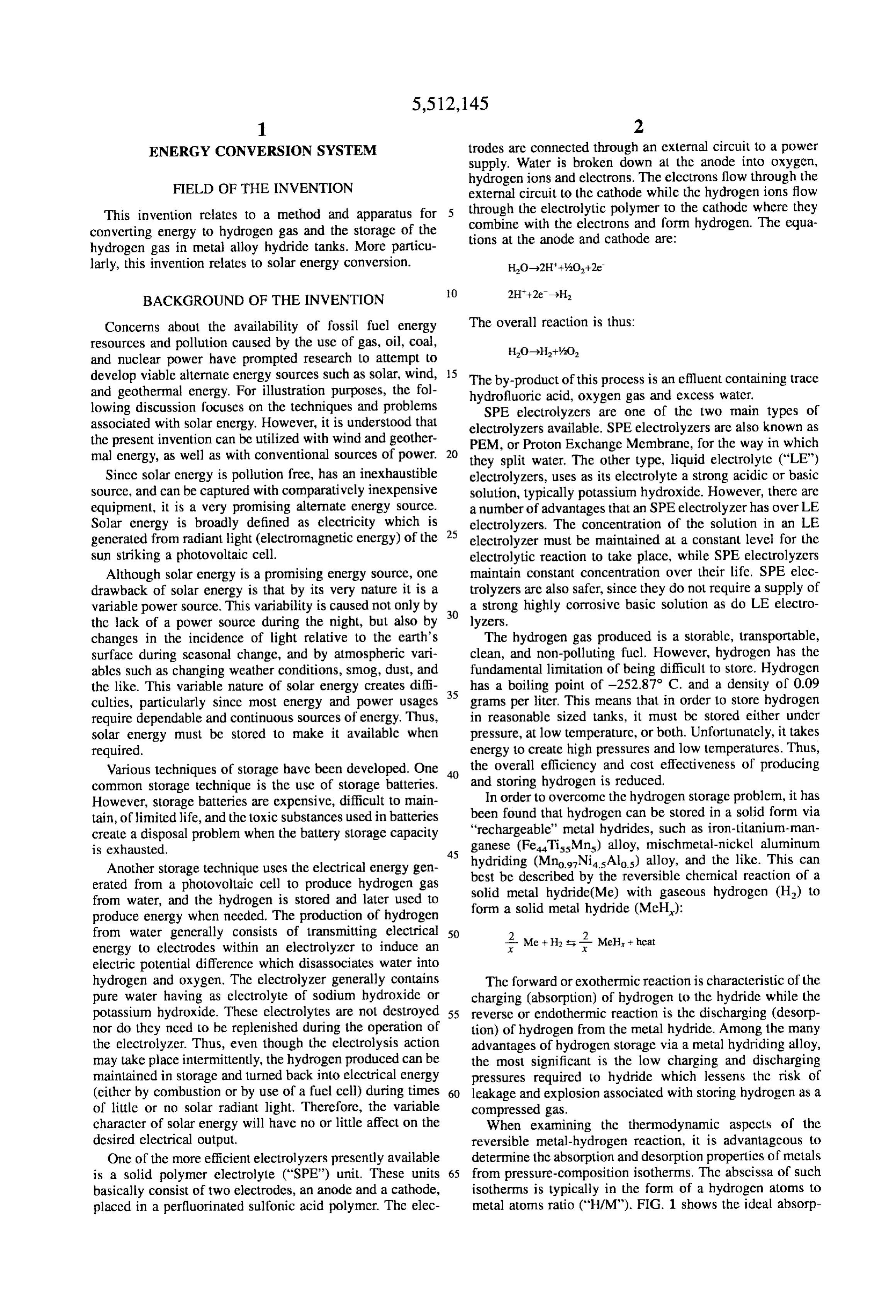
Another storage technique uses the electrical energy gen hydriding (MnogNias Alo) alloy, and the like. This can erated from a photovoltaic cell to produce hydrogen gas best be described by the reversible chemical reaction of a from water, and the hydrogen is stored and later used to solid metal hydride(Me) with gaseous hydrogen (H) to produce energy when needed. The production of hydrogen form a solid metal hydride (MeH): from water generally consists of transmitting electrical 50 2 Me + H, i. 2. McH, theat energy to electrodes within an electrolyzer to induce an electric potential difference which disassociates water into hydrogen and oxygen. The electrolyzer generally contains The forward or exothermic reaction is characteristic of the pure water having as electrolyte of sodium hydroxide or charging (absorption) of hydrogen to thc hydride while the potassium hydroxide. These electrolytes are not destroyed 55 reverse or endothermic reaction is the discharging (desorp nor do they need to be replenished during the operation of tion) of hydrogen from the metal hydride. Among the many the electrolyzer. Thus, even though the electrolysis action advantages of hydrogen storage via a metal hydriding alloy, may take place intermittently, the hydrogen produced can be the most significant is the low charging and discharging maintained in storage and turned back into electrical energy pressures required to hydride which lessens the risk of (either by combustion or by use of a fuel cell) during times 60 leakage and explosion associated with storing hydrogen as a of little or no solar radiant light. Therefore, the variable compressed gas.
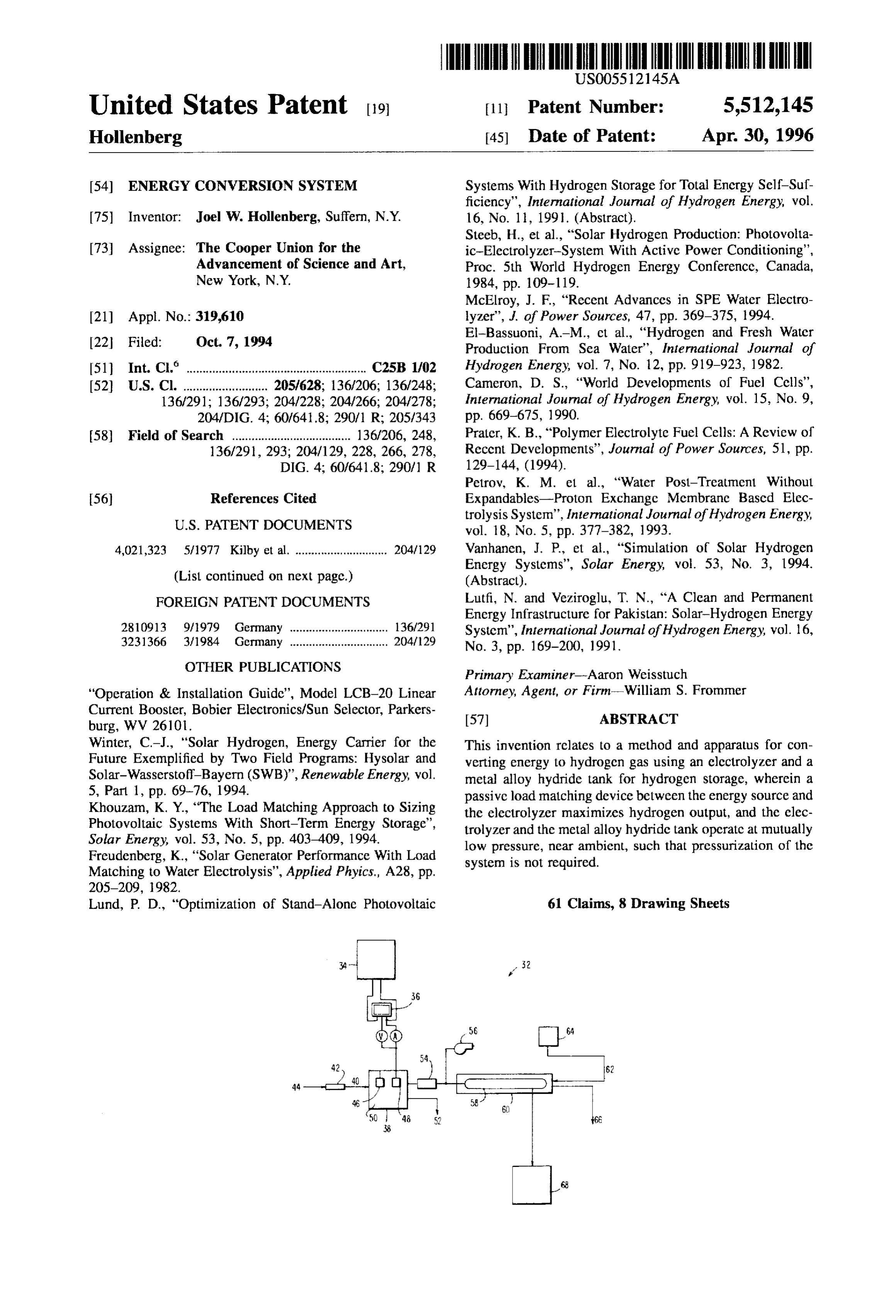
character of solar energy will have no or little affect on the When examining the thermodynamic aspects of the desired electrical output. reversible metal-hydrogen reaction, it is advantageous to One of the more efficient electrolyzers presently available determine the absorption and desorption properties of metals is a solid polymer electrolyte ("SPE') unit. These units 65 from pressure-composition isotherms. Thc abscissa of such basically consist of two electrodes, an anode and a cathode, isotherms is typically in the form of a hydrogen atoms to placed in a perfluorinated sulfonic acid polyncr. Thc elec metal atoms ratio ("H/M"). FIG. 1 shows the ideal absorp
Page 12
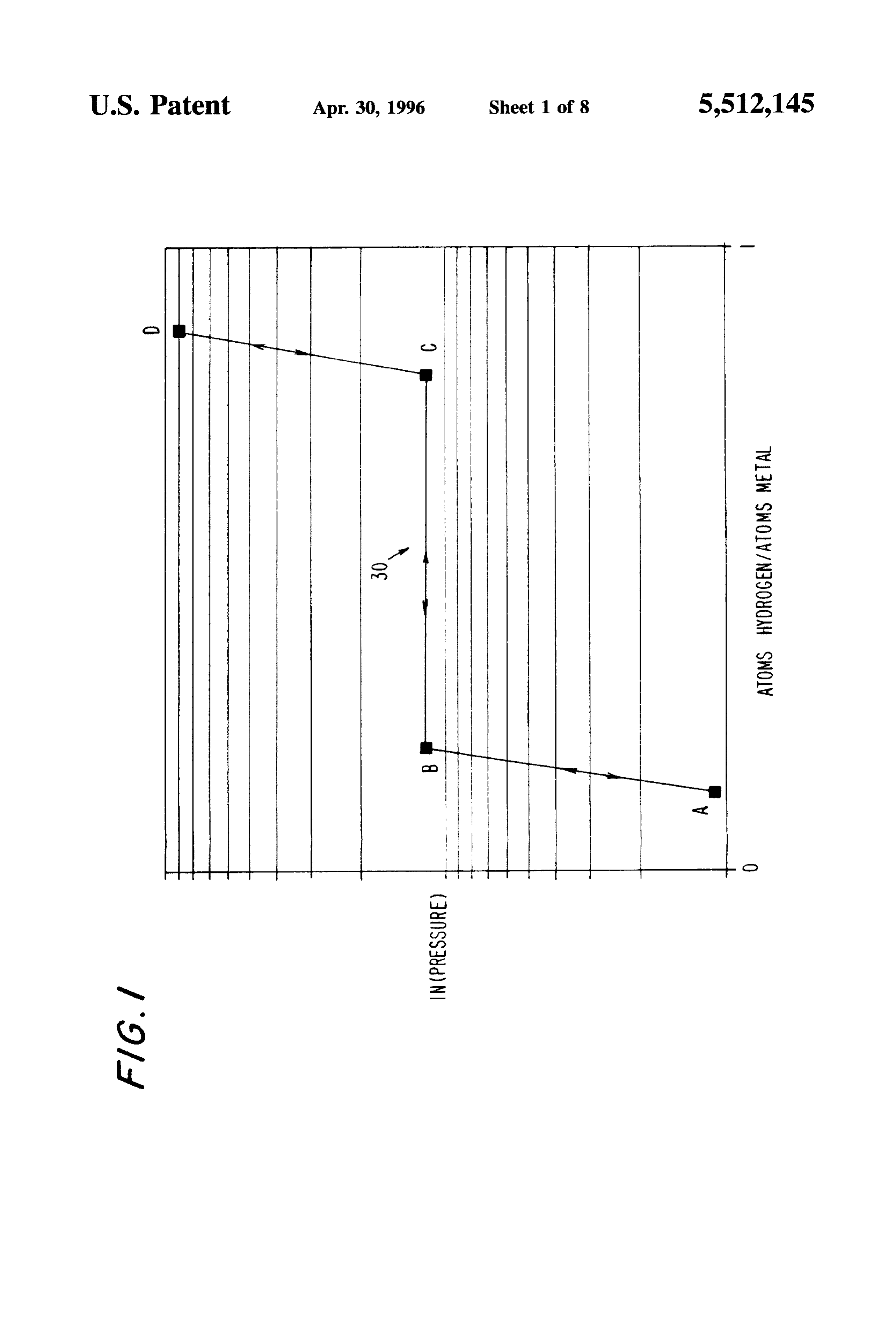
lion-desorption pressure-composition isotherm for a metal The goal of the project was to develop the required tech hydrogen system where the plateau pressure ("P") 30 is nologies and demonstrate the technical feasibility of a shown connecting points B and C. Once the plateau pressure hydrogen storage system with electrolytic hydrogen produc is reached, the majority of the absorption or desorption of tion and electrical power production using hydrogen fuel. A hydrogen takes place at this constant pressure P. The curves pilot system is currently being constructed for a 1-4 kW-hr connecting points A and B as well as points C and D show daily load. The system disclosed uses battery storage and that for a large increase or decrease in pressure, the amount pressurized hydrogen storage, and achieves load matching of hydrogen absorbed or desorbed is small. by switching components on and off. in reality, while such isotherms as shown in FIG. 1 might A similar project was also undertaken at Humboldt State be achievable, most hydrides deviate from this ideal behav University in Arcata, Calif., with the Schatz Solar Hydrogen ior. In addition to the fact that the plateau region slopes and Project. The results of the California project were published the boundaries of this region are not as well defined, there in "Project Hydrogen '91: Technical Proceedings,” Amer. also exists hysteresis between absorption and desorption curves. For ideal hydrides, there is no means by which to Acad of Science (1992). The California system consisted of measure the composition of the hydride when located along 5 a 9.2 kW photovoltaic array connected in parallel to a 24 the plateau pressure; but the slope in the isothern for real VDC, 37-Ahr nickel-cadmium battery and a Teledync metals makes finding the hydrogen to metal ratio as simple Energy ALTUS 20M liquid potassium-hydroxide electrolyte as knowing the temperature and pressure of the hydride. electrolyzer capable of producing 20 slpm of hydrogen and The plateau pressure P is related to the absolute tem drive 10 slpn of oxygen. The hydrogen and oxygen were used to perature of the reaction, T., by the Van't Hoff equation: an Ergenics 1.0 kW fuel cell, and when the fuel cell was not in use, the hydrogen and oxygen were stored as
AH AS compressed gases in separate tanks.
in(P) = RTR R Finally, photovoltaic energy storage in the form of hydro gen fuel has also found application as a means of vehicle where AH is the change in enthalpy, AS is the change in propulsion. One noteworthy project currently under devel entropy and R is the universal gas constant. From the Van't 25 opment is the LaserCelTM prototype vehicle at The American Hoff relationship one can dcter mine the charging and dis Academy of Science. The results of this LaserCelTM project charging pressures and temperatures of the tank. were published in "Project Hydrogen '91: Technical Pro Experimental work into hydrogen storage for photovol ceedings,' Amer. Acad of Science (1992). A subcompact car taic systems has been performed at Brookhaven National (modification of a Ford "Fiesta') was powered by a Laser Laboratories. This experimental work has been published in 30 CelTM inhouse-developed SPE hydrogen-air fuel cell, driv Schoener et al., "An Integrated Test Bed For Advanced ing an electric motor coupled to the wheels using a standard Hydrogen Technology: Photovoltaic Array/Electrolyzer transmission. The hydrogen was stored as a metallic hydride System," BNL51577 Brookhaven National Laboratory in tanks containing an iron-titanium-manganese (1982), Leigh et al., “Photovoltaic-electrolyzer System (FeTi5Mns) alloy, and a gas compressor was used to raise Transient Simulation Results.' BNL40081 Brookhaven 35 the hydrogen and air to the operating pressure of the fuel National Laboratory (1983), and Metz et al., “Photovoltaic cell. Heat exchange to extract or store hydrogen from the powered Solid Polymer Electrolyte (SPE) Electrolyzer Sys tanks was achieved using thermoelectric heat pumps, and tem Evaluation,' BNL51940 Brookhaven National Labora the fuel cell could be operatcd in reversc as an electrolyzer tory (1982). The system of the prior art consistcd of a 5 kW to produce hydrogen (from a specially designed water photovoltaic array, a 15 kW advanced technology electro 40 supply built into the vehicle) for storage. Solar panels could lyzer, and an iron-titanium hydride tank with a storage be mounted on the vehicle so that it can literally produce its capacity of 50 lbs or 8600 standard ft of hydrogen. This own fuel in this fashion (under favorable sunlight condi Brookhaven system used a power conditioner between the tions). The vehicle was said to have a range of 300 km, photovoltaic array and electrolyzer that also drew power extendable to 500 km, and great emphasis was made of the from local utilities to supplement the 5 kW array. This was 45 fact that hydrogen consumption in a fuel cell is two to three done to allow the advanced technology electrolyzer to be times more efficient than burning it in an internal combus opcrated off the utilities for baseline constant power testing, tion engine.
and to simulate a 100% solar power source. It was found that As it can be seen, although the technologies for the use of an activc power conditioner would entail losses collection and use of photovoltaic energy, electrolysis, and ranging from 21–29%. 50 the storage of hydrogen in various forms are established A similar analytical model for a photovoltaic array either theoretically or by actual applications, virtually no electrolyzer system was constructed at the Institute for work has been done in combining the three technologies into Technical Physics in West Germany. The results from this an integrated hydrogen production and storage system for model were published in Carpetis, C., "An Assessment of photovoltaic energy conversion to achieve a viable means Electrolytic Hydrogcn Production by Means of Photovoltaic 55 for the production of hydrogen in an efficient manner. Energy Conversion." Int'l J. Hydrogen Energy, Vol. 9, No. Thus, there is a need for an apparatus for hydrogen 12 (1990) pp. 969-991. From the Carpetis model, it was production from alternate energy sources in an efficient determined that the use of a power conditioner would not manner and which is able to storic hydrogen in a manner improve system performance, since it would increase power which does not require a substantial consumption of energy. losses from 5% without conditioning to 5-10%. 60
Since 1990, the Department of Technical Physics at the OBJECTS OF THE INVENTION Helsinki University of Technology has undertaken a three year project to investigate hydrogen energy technologies for A primary object of this invention is to provide an solar energy systems at high latitudes. The results of this apparatus and method for producing hydrogen efficiently project were published in Kauranen et al., "Hydrogen 65 from an alternate energy source.
Energy Storage for Photovoltaic Systems,' Helsinki Uni It is a further object of this invention to provide an versity of Technology, Dept. of Technical Physics (1990). apparatus and method for producing hydrogen efficiently
Page 13
S 6 from an alternate energy source which includes an electro reactions occurring with the metal hydride to allow the lyzer for disassociation of water into hydrogen and oxygen system to operate at sufficiently low pressures (near ambi from the energy received from the alternate energy source ent) and thereby eliminate the need for holding the system with a means for regulating the electrical input to the under pressure.
electrolyzers to maximize the hydrogen production. The hydrogen produced is stored as a solid hydride when It is still a further object of this invention to provide an not in usc, which eliminates the inconveniences and hazards apparatus and method for producing hydrogen efficiently associated with storing hydrogen as a compressed gas. from an alternate energy source which includes an electro Operating the solid hydride storage system and clectrolyzer lyzer for disassociation of water into hydrogen and oxygen at low pressures lessens the chance of leakage and explo from the energy received from the alternate energy source O sion, allows simpler sealing configurations, allows for the and metal hydride tanks for storing hydrogen wherein the use of less expensive construction materials, lessens the electrolyzer and metal hydride source tanks are designed to chance of structural fatiguc, allows for easy assembly of the operate at near atmospheric pressure. entire system, and eliminates compressor pulsations and/or It is yet a further object of this invention to provide an vibrations which can cause structural damage and leakage. apparatus and method for producing hydrogen efficiently 5 A significant advantage of the system is that hydrogen is from an alternate energy source which includes an electro produced in a steady supply using only watcrand either solar lyzer for disassociation of water into hydrogen and oxygen energy, wind power, or the like, which are practically from the energy received from the alternate energy source inexhaustible.
with a means for regulating the electrical input to the An attractive aspect of the use of photovoltaic energy in electrolyzers to maximize hydrogen production, and which 20 the formation of hydrogen fuel is that hydrogen is cnviron further includes metal hydride tanks for storing hydrogen mentally benign. It can be burned in air without producing wherein the electrolyzer and metal hydride tanks are excessive amounts of greenhouse gases or other pollutants designed to operate at near atmospheric pressure. attributed to hydrocarbon or fossil fuels. Hydrogen can also The above and other objects, features and advantages of 25 be used to power a fuel cell to gencrate electricity directly, this invention will be apparent in the following detailed with the only by-product being water. The present invention description of illustrative embodiments thereof. can thus demonstrate the potential of hydrogen fucl as an alternatic source of energy when produced in this safe and
SUMMARY OF THE INVENTION clean manner.
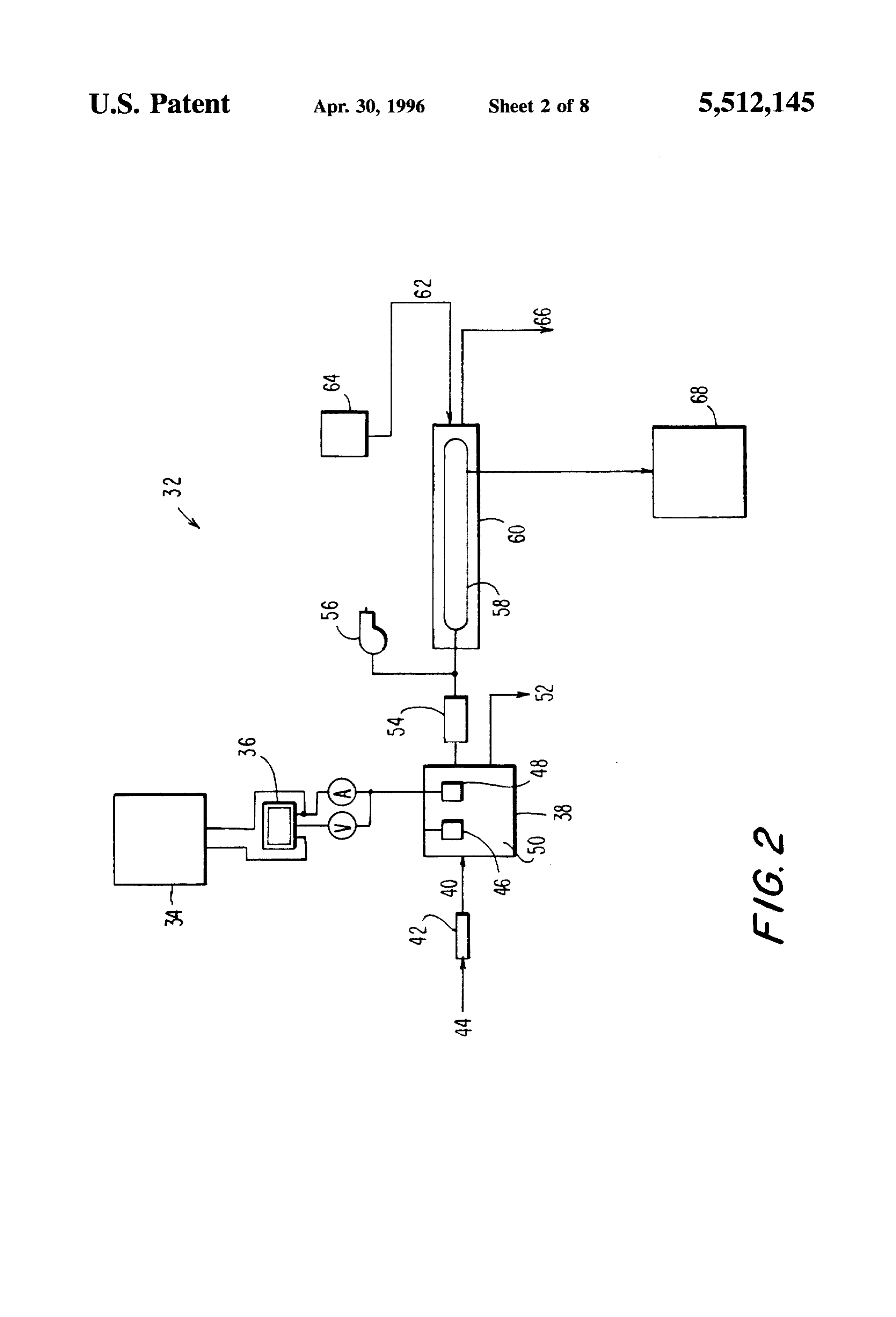
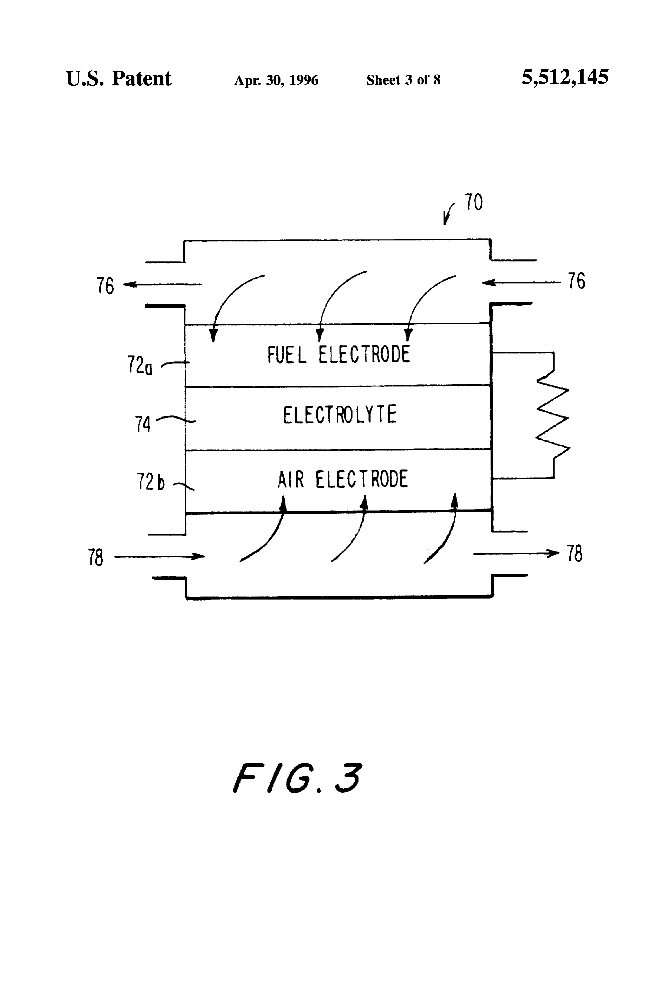
This invention relates to a method and apparatus for BRIEF DESCRIPTION OF THE DRAWINGS converting energy to hydrogen gas and the storage of the hydrogen gas in mctal alloy hydride tanks. More particu While the specification concludes with claims particularly larly, this invention relates to solar energy conversion. pointing out and distinctly claiming that which is regarded In an effort to overcome the numerous disadvantages 35 as the present invention, the objects and advantages of this associated with the production and storage of hydrogen gas invention can be more readily ascertained from the follow generated from alternate energy sources, particularly vari ing description of the invention when read in conjunction able type alternate energy sources, and to address the with the accompanying drawings in which: problem of storing photovoltaic energy for use during peri FIG. 1 is a plot showing the ideal absorption-desorption ods of inadcquate or no sunlight, the present invention 40 pressure-composition isotherm for a metal-hydrogen sys utilizes a novel apparatus for efficiently producing and tel.
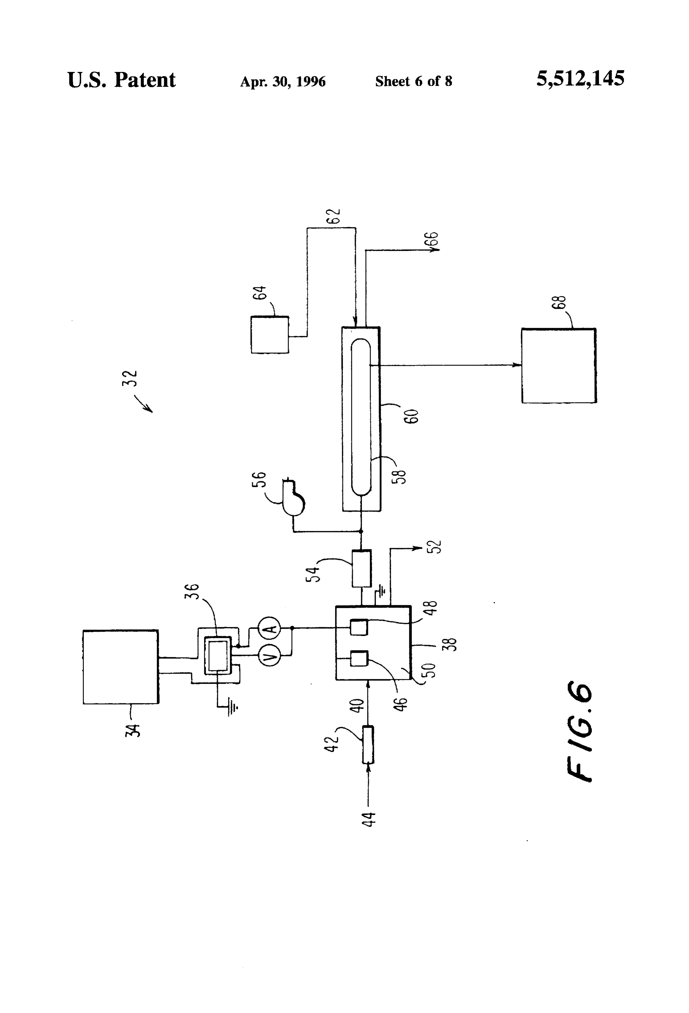
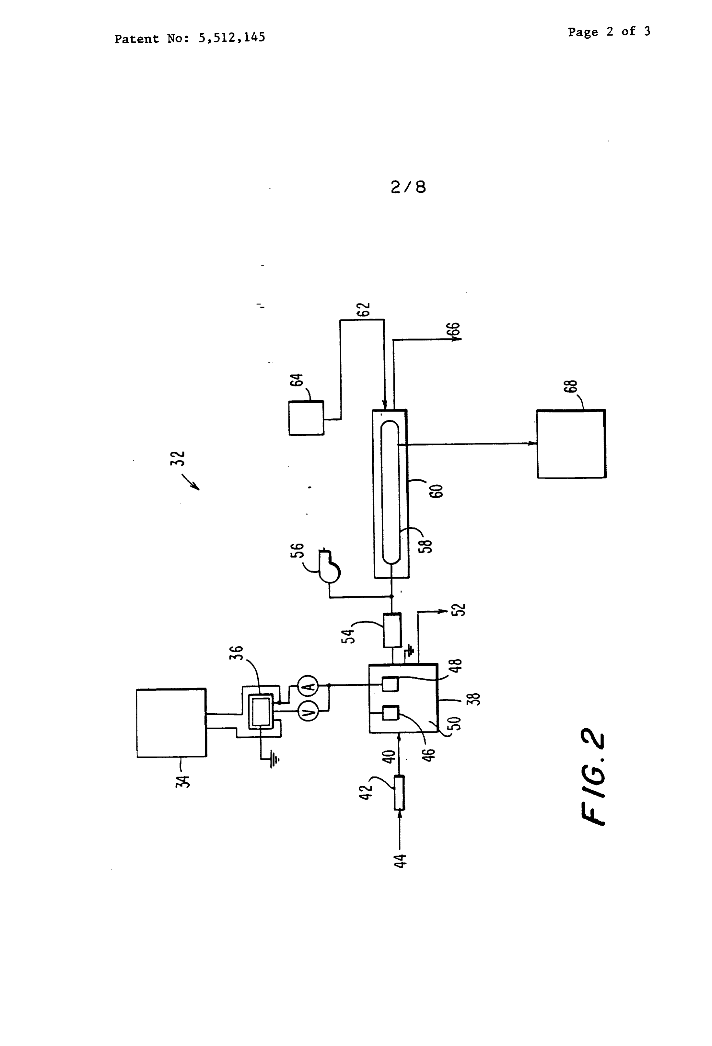
storing hydrogen fuel which can be used as an environmen FIG. 2 is a schematic illustration of the basic apparatus of tally-safe fuel for both heating and electric power genera the present invention.
FIG. 3 is a schematic illustration of an individual hydro
The invention primarily is comprised of four components. 45 gen-air fuel cell.
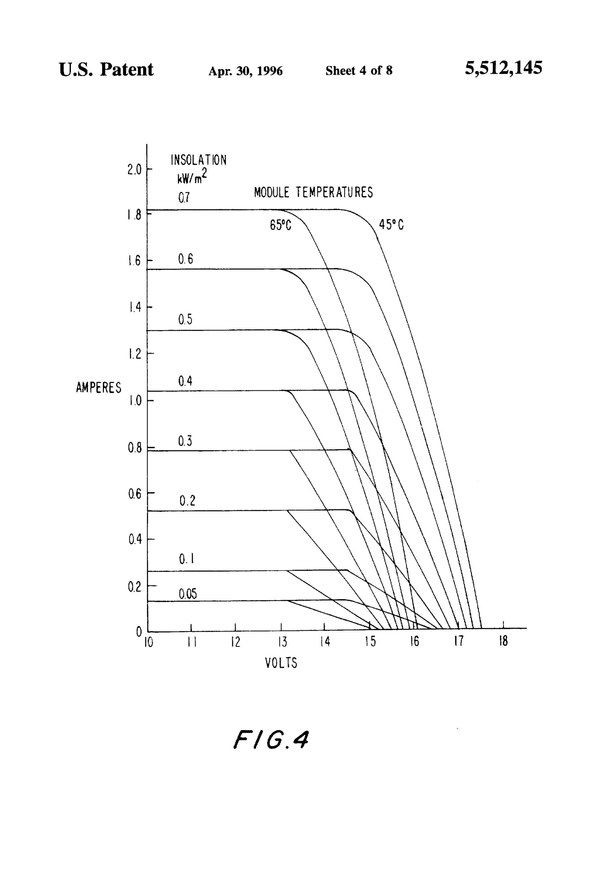
First, an energy collector, such as a photovoltaic array used FIG. 4 is a plot of typical performance curves of a to collect solar energy and convert it to electrical power, a photovoltaic array which shows how performance is affected windmill used to collect wind power and convert it to by changes in insolation and temperature. electrical power, and the like. This component includes a passive load matching device (linear current booster) to 50 FIG. 5 is a plot of the time history of current to an convert excess voltage from the energy collector to current, electrolyzer before and after the use of a load matching and to maintain the output voltage at a constant value. device.
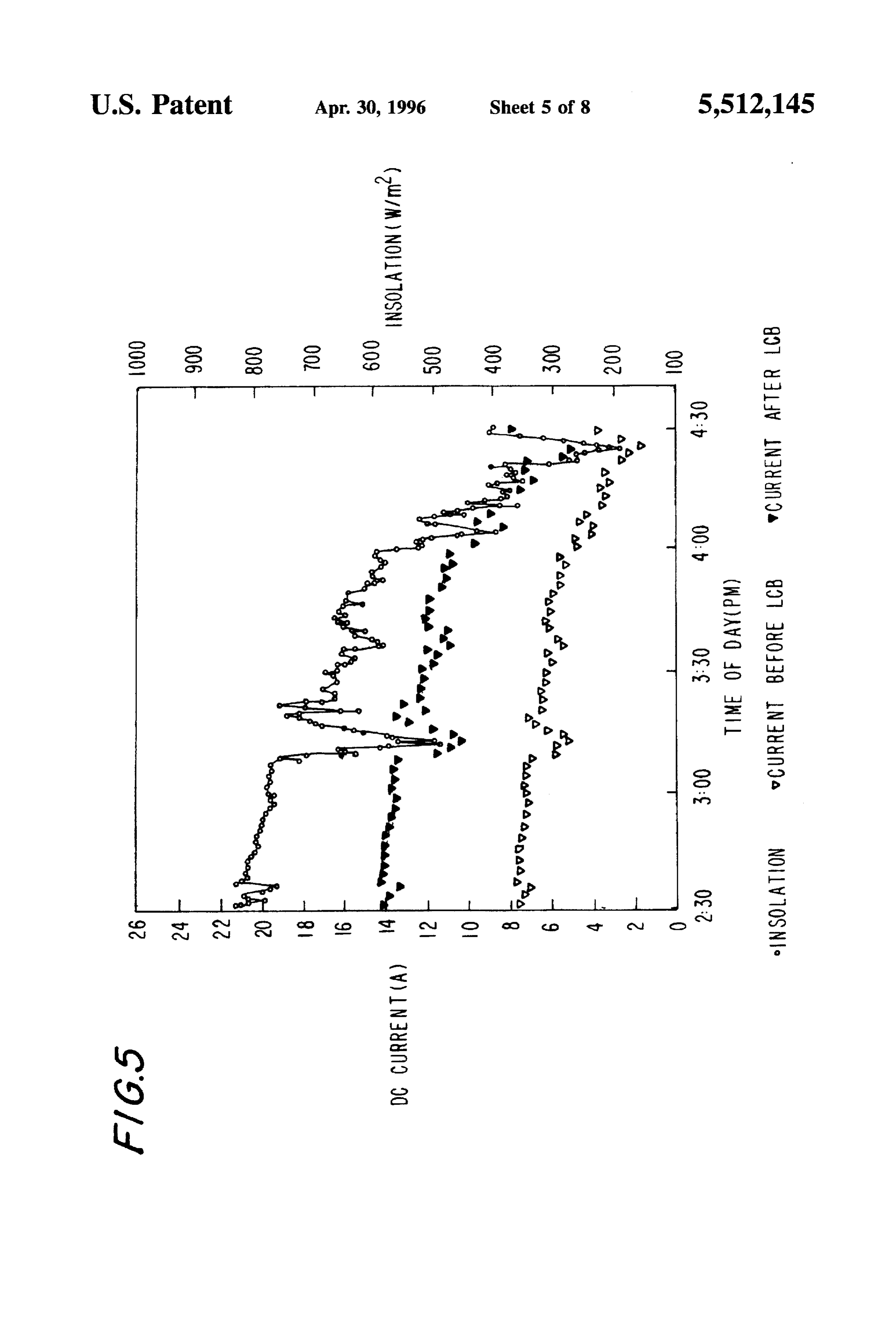
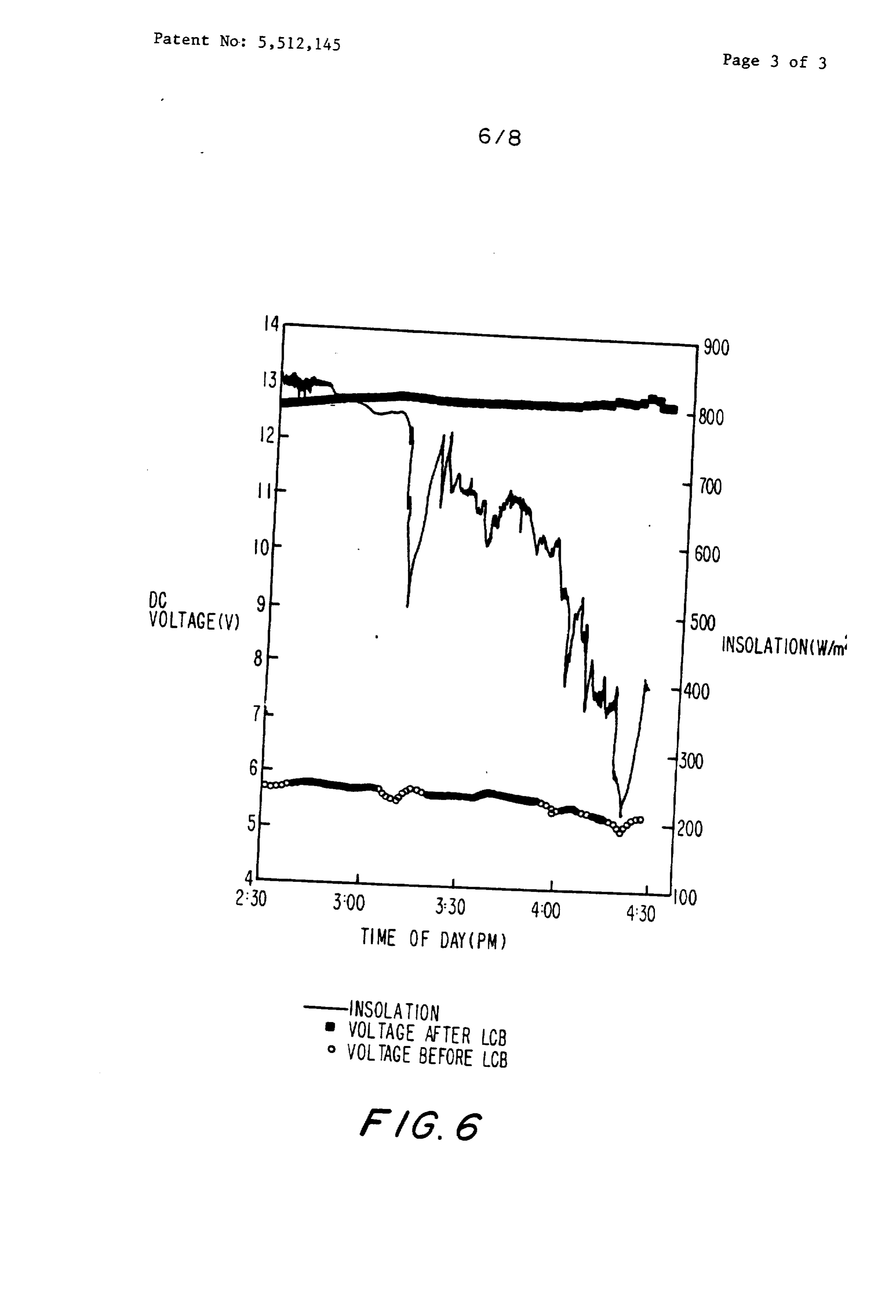
Second, an electrolyzer which receives direct current FIG. 6 is a plot of the time history of voltage to an ("DC") electric input from thc energy collector to power electrolyzer before and after the use of a load matching electrolyzer cells that generate hydrogen from water. Third, 55 device.
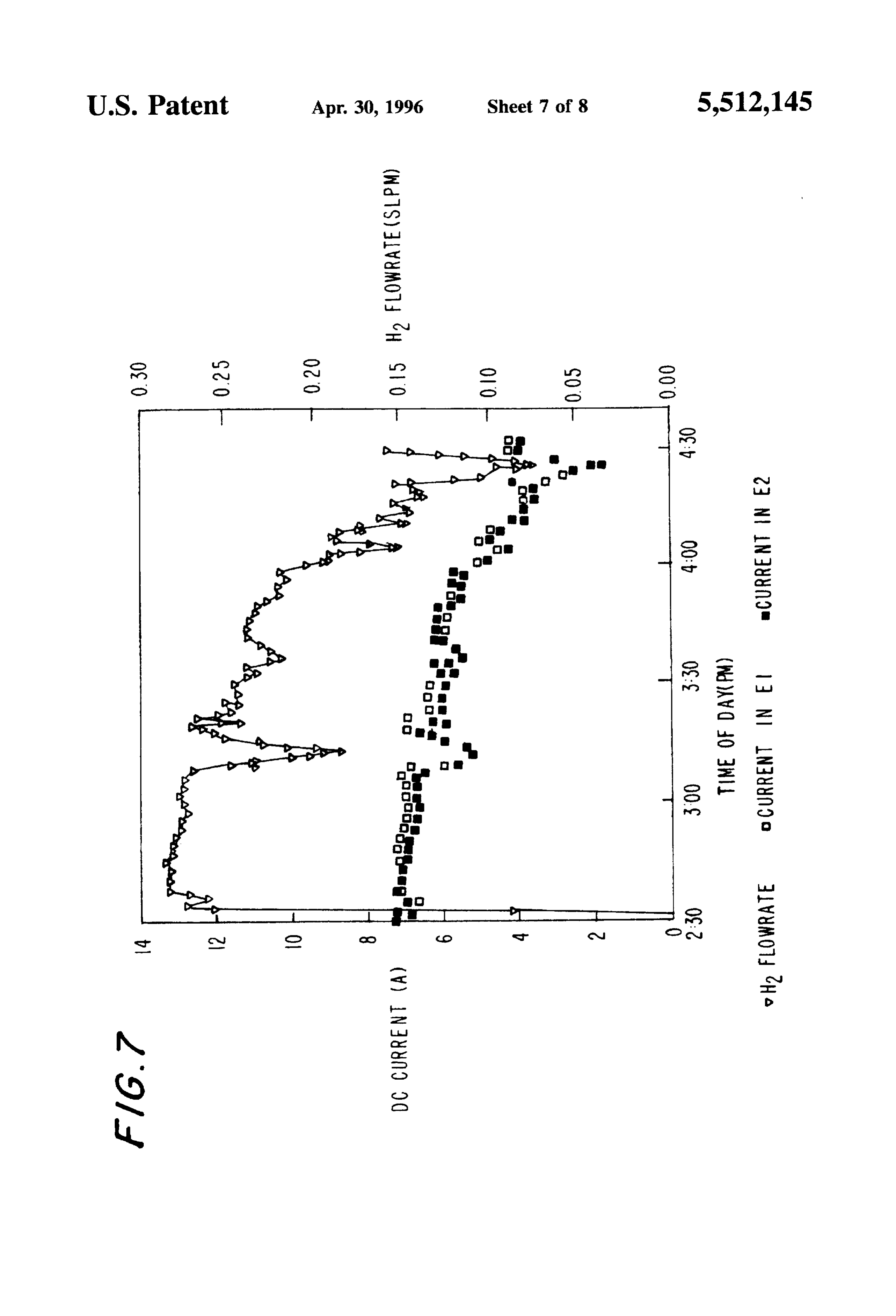
a hydrogen store, such as a solid metallic alloy hydride FIG. 7 is a plot of the time history of the hydrogen which stores hydrogen through a reversible chemical pro flowrate to the storage tank.
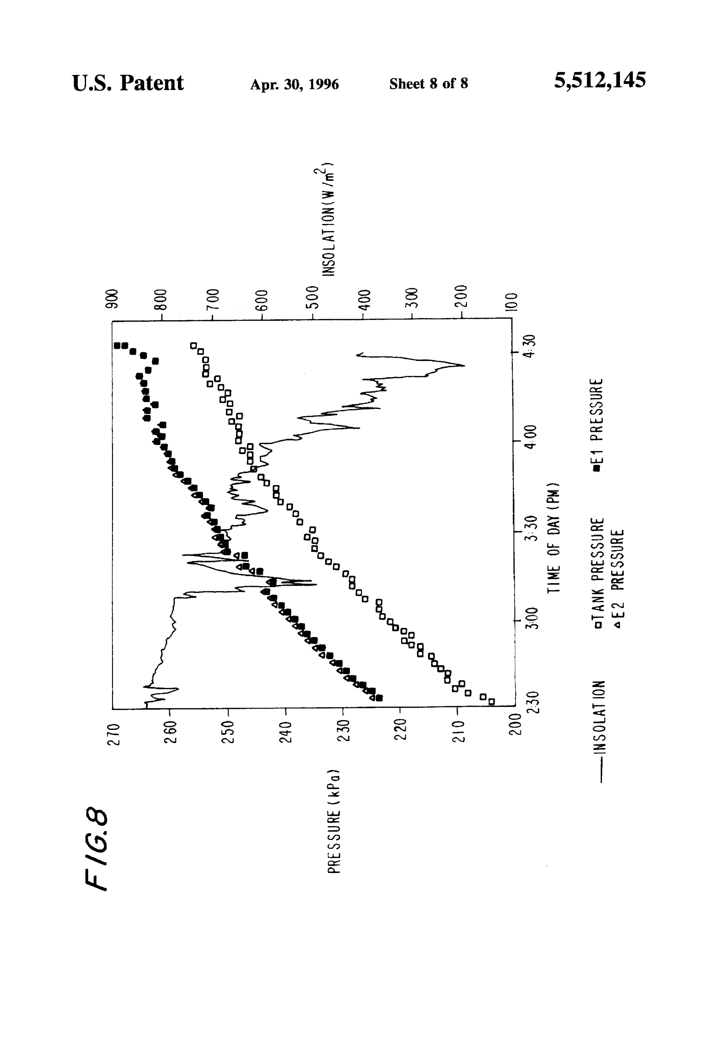
cess. Fourth, a hydrogen consumption device, such as a FIG. 8 is a plot of the time history of the pressure burner or a fuel cell which consumes the hydrogen released characteristics of two electrolyzers and the storage Lank from the tanks (using a heat exchange process) to provide being charged with hydrogen therefrom. electricity.
An important feature of the present invention is the use of DETAILED DESCRIPTION OF THE a passive load matching device (linear current booster) INVENTION between the photovoltaic array and the electrolyzer to con vert excess voltage as may be produced by the photovoltaic 65 As discussed previously, this invention relates to a method panel to current. Another feature is matching the specifica and apparatus for converting energy to hydrogen gas and the tions of the electrolyzer to the hydriding and dehydriding storage of the hydrogen gas in metal alloy hydridc tanks.
Page 14
More particularly, this invention relates to solar energy a mischmetal-nickel aluminum hydriding alloy whose conversion. chemical composition is given by Mng NiAs, com In FIG. 2, a hydrogen gas generation apparatus 32 is mercially known as HYSTOR-208TM, which has ability to schematically illustrated. An energy source 34, such a pho charge and discharge at readily available cooling and heating tovoltaic array collecting solar energy, an electrical genera water temperatures (between 40° F to 200 F). The hydro tor powercd by a windmill, or the like, is electrically gen storage tank 58 is surrounded by a water jacket 60 that connected to a passive load matching device (linear current facilitates heat exchange during absorption and desorption booster) 36. The output current from the energy source 34 is of hydrogen gas in and out the metal hydride. The hydrogen conditioned through the passive load matching device 36 storage tank 58 is preferably oversized in comparison to the which couples the energy source 34 to an electrolyzer 38, O heat hydrogen producing capacity of the electrolyzer 38, so the preferably a solid polymer electrolyte (perfluorinated sul of reaction during hydriding from the electrolyzer fonic acid) electrolyzer, which uses the energy from the output results in a negligible cooling water temperature rise energy source 34 to disassociate water into hydrogen and using normal water flow rates through the water jacket 60. oxygen. The passive load matching device 36 provides Hydrogen energy storage in a solid form via a "recharge adequate load-matching between the energy source 34 and 5 chemicalable” metal hydride can best be described by the reversible the clcctrolyzer 38, of thc unsteady power generated by the reaction of a solid metal hydride (Me) with gas eous hydrogen (H) to form a solid metal hydride (MeH):
cnergy source, and converts excess voltage to current. Since hydrogen production from the electrolyzer 38 is directly 12. Me + H2 s. 2. Meh -- heat dependent on the electrical current supplied by the energy source 34, an increase in hydrogen production results from the current-boosting capability of the passive load matching The forward or exothermic reaction is characteristic of the device 36. charging (absorption) of hydrogen to the hydride while the Deionized water 40 is supplied to the electrolyzer 38 from reverse or endothermic reaction is the discharging (desorp a deionizer 42 which deionizes a water supply 44. The water tion) of hydrogen from the metal hydride. Among the many advantages of hydrogen storage via a metal hydriding alloy, supply 44 can be either fresh water or sea water. The 25 one of the more significant is the low charging and discharg deionized water 40 is supplied to the clectrolyzer 38 for ing pressures required to hydride. The preferred metal disassociation into hydrogen and oxygen. The electrolyzer hydride for use in the hydrogen storage tank 58, a mis 38 includes an anode 46 and a cathode 48, placed in a chmetal-nickel aluminum alloy with the molecular formula perfluorinated sulfonic acid polymer 50. At least one of Mnoonis Alos, has the ability to charge in a low pressure electrodes 46 and 48 is electrically connected via the passive 30 range. It was also found that the preferred electrolyzer 38, load matching device 36 to the energy source 34. When namely the solid polymer electrolyte (perfluorinated sul power is delivered from the energy source 34 to the elec fonic acid) electrolyzer, has a low electrolytically generated trolyzer 38, the deionized water is broken down at the anode pressure range such that the metal hydride can be charged 46 into oxygen, hydrogen ions and electrons. The electrons without the need for pressurization via an external compres flow through the external circuit to the cathode 48 while the 35 SO.
hydrogen ions flow through the electrolytic polymer 50 to The hydrogen gas reacts with the metal alloy granules in the cathode 48 where they combine with the electrons and the hydrogen storage tank 58 at a specific temperature and form hydrogen. The equations at the anode 46 and cathode pressure according to the Van't Hoff equation, liberating 48 are: heat in the process. Heat, preferably in the form of hot water 40 62 provided by an external water heating source 64, can be supplied to the hydrogen storage tank 58 via the water jacket
58 to discharge the hydrogen gas from the metal hydride for utilization as required. The used hot water 62 exits the water
The overall reaction is thus: jacket 58 via water drain 66. The hydriding and dehydriding 45 reactions in the preferred metal hydride, mischmetal-nickel
HO-H+%O aluminum alloy, occur at convenient temperatures and at pressures.
The by-product of this process is an effluent 52 containing Once the hydrogen is stored, it can be later be sent for use trace hydrofluoric acid, oxygen gas and excess water. It is in a hydrogen converter 68. The hydrogen converter 68 noted that the oxygen can be recovered as a product. 50 preferably is a hydrogen engine where hydrogen is burned in The electrolytically generated hydrogen is dried of its air for heat or for generating electricity, without producing water vapor content, then purified by purifier 54 to less than excessive amounts of greenhouse gases or other pollutants 10 ppm impurities. Numerous means of purification can be attributed to hydrocarbon fuels. Alternatively, the hydrogen used. However, molecular sieves and desiccators, such as a converter 68 may a fuel cell to generate electricity directly, Matheson PF-H2 PURIFILTERTM or a Supelco OMITM-1 55 with the only by-product being water.
indicating purifier, are preferred. FIG. 3 schematically shows an individual hydrogen-air Once purified, the hydrogen gas is delivered to a hydrogen fuel cell 70 that may be used as hydrogen converter 68, storage tank 58 at pressures produced by the electrolyzers comprised of two electrodes, fuel electrode 72 and air 38, preferably in the range of 0-100 psig. A vacuum pump electrode 73 which are separated by an electrolyte 74. 56 is optionally included between the electrolyzer 38 and the 60 Hydrogen 76 is delivered to the fuel electrode 72 which is hydrogen storage tank 58 for purging the hydrogen flowpath the anodic, and air 78 is delivered to the air electrode 73 as part of the startup procedure. which is the cathode, The hydrogen dissociates at the fucl The hydrogen storage tank 58 is preferably composed of electrode 72 into hydrogen ions and electrons. The hydrogen multiple tubcs containing "rechargeable' metal hydrides, ions pass through thc electrolyte 74 to the air electrode 73 such as iron-litanium-manganese alloy, mischmetal-nickel 65 where they combine with the electrons that have passed aluminum hydriding alloy, and the like. Preferably, the through the external load 75, therchy generating an electrical multiple tubes of the hydrogen storage tank.58 are filled with Currell.
Page 15
An electric potential is established and electric current device is a linear current booster ("LCB") manufactured by may be drawn as long as the hydrogen 76 and air 78 are Bobier Electronics (Bobier Electronics LCB-20) and is supplied. The electrodes 72 and 73 catalyze the reaction but designed to be adjusted to be compatible with the parameters are not consumed; therefore, the fuel cell 70 has a potential and specifications of the photovoltaic array. The LCB pro for long life. The fundamental electrochemical process is vides adequate load-matching of the unsteady DC power highly efficient and virtually pollution-free. These charac generated by the photovoltaic array between the photovol teristics are independent of output power. Individual fuel taic array and clectrolyzer, and converts excess voltage to cells 70 can be assembled in series to generate practically current, resulting in a greater production of hydrogen from any desired voltage. Connecting fuel cell assemblies in the electrolyzer. As discussed below, the electrolyzers arc parallel permits practically any power output. The fuel cells O rated with a maximum voltage of 6.8 volts. Therefore, i? 70 generate DC current, therefore a fuel cell requires a solid electric output from the photovoltaic array had a voltage state invertor to produce regulated, conventional AC current. greater than 6.8, the excess voltage was converted to current. A valuable by-product of the fuel cell is purified, potable Linear current boosters were developed to regulate battery water. Even more important, potable water can be produced charging in photovoltaic system. However, linear current as a by-product from the fuel cell when sea water is used in 5 boosters have never before been used for load matching in the electrolyzer 38. Therefore the system, in addition to photovoltaic panels to an electrolyzer. producing power, can desalinate sea water to produce It is, of course, understood that other types of load potable water. matching devices could be utilized in the present system. The following example is being presented not as a limi These other devices include, but are not limited to, using a tation but to illustrate and provide a better understanding of 20 switching network with controls to turn electrolyzer cells on the invention, as well as to illustrate the importance of and off, using a direct current motor driven by the photo certain steps utilized in the present process. voltaic panels which drives a direct current generator limited to output a fixed voltage and varying current (with necessary
EXAMPLE controls), or using a battery charging system run by the 25 photovoltaic panels where the batteries supply electric
The present example utilized a photovoltaic array collect power to the electrolyzers through a regulator and controls. ing solar energy for the power input. The photovoltaic array The system was designed to use three Aadco Instruments, converts incident radiant energy to electrical energy. The Inc., 3-cell solid polymer electrolyte ("SPE") (perfluorinated two operating conditions of importance for a solar cell are its sulfonic acid) electrolyzers, rated at 0.225 slpm maximum insolation or the quantity of radiant energy incident upon the 30 hydrogen gas output, and each rated at a maximum voltage photovoltaic array and the photovoltaic array temperature. of 6.8 volts and a maximum current of 14 amperes (however, For maximum power output, high insolation and low tem one electrolyzer was malfunctioning, thus the example data perature are desirable. Due to these two variables, the power was generated with only two electrolyzers). The hydrogen output varies daily. However, since the primary source of flow rate from the array was directly dependent on the energy is the sun, it offers predictable availability, no cost, 35 current supplied thereto and hence an increase in hydrogen and significant environmental advantages. production is a result of the current-boosting capability of The photovoltaic array's power, totaling 150 watts maxi the power conditioning device. Deionized water with a mum, was derived from two Solarwest Electric ASI resistance of at least 30 k2 at standard room temperatures 16-2000TM photovoltaic panels with maximum power output 40 was required for hydrogen production. Thc deionized water of 35W per panel and two Arco M-73TM photovoltaic panels was supplied to the electrolyzers which produced, as out with maximum power output of 40W per panel. puts, oxygen gas, which was safely vented (although the The performance of a photovoltaic cell can be expressed oxygen could be recovered as a product), and hydrogen gas. graphically by a plot of current vs. voltage. A performance The electrolytically generated hydrogen was first dried of its curve essentially is a locus of the operating points of the 45 water vapor content, then purified by a Mathcson PF-H2 photovoltaic cell under various loads, FIG. 4 is a plot of PURIFILTERTM (molecular sieve and desiccator) to less typical performance curves and it shows how the perfor than 10 ppm impurities in order to prevent "poisoning" of mance of the photovoltaic array is affected by changes in the metal hydride.
insolation and temperature. It is, of course, understood that a variety of purifiers For an increase in temperature at a given insolation, the 50 known in the art can be used so long as impurities are current is nearly constant, while the open circuit voltage sufficiently removed. A method of removing impurities decreases. However, the current is directly proportional to could also include removing oxygen contaminants from the the level of insolation, and therefore, increasing the insola hydrogen by using a laser to react the oxygen contaminants tion produces an increase in current. The open circuit with the hydrogen to form water vapor which can be easily voltage is also affected by changes in insolation, but the 55 removed in the desiccator.
effects are relatively small. One can conclude from the plot Once purified, the hydrogen gas was sent to metal hydride of current vs. voltage that enhanced performance occurs at hydrogen storage tanks at pressures in the range of 0-100 high insolation and low temperatures. One important point psig, i.e. the pressure produced by the electrolyzers. A on the performance curves is the knee of the insolation vacuum pump was placed between the electrolyzer and the voltage curve, which denotes the point of maximum power. 60 hydrogen storage tank for purging the hydrogen flowpath as One problem that occurs when using photovoltaic panels part of the startup procedure.
with an electrolyzer is that the photovoltaic panels can easily The hydrogen storage tank was composed of two Ergenics exceed the maximum voltage limit of the electrolyzers. This ST45TM hydride tanks. Each tank was comprised of seven problem is solved by the present invention by routing the stainless steel-304 tubes with each tube containing six l" direct current output from the photovoltaic array through a 65 OD aluminum capsules. Each capsule was filled with 250 passive load matching device which couples the photovol grams of a mischmetal-nickel aluminum hydriding alloy taic array to an electrolyzer. The passive load matching whose chemical composition is given by Mnoo, Nias Alos,
Page 16
commercially known as HYSTOR-208M, and capped with an electrically operated electrolyzer operable at an opti a 2 porous stainless steel filter on each end. The total mum operating voltage to convert water into hydrogen hydride mass in each tank was 10.5 kilograms, which and oxygen, and equates to over 45 standard cubic feet (1,274 standard liters) a passive load matching means electrically connecting the of hydrogen storage. A common inlet/outlet port provided 5 energy source to the electrolyzer for converting any for hydrogen charging and discharging to and from the seven voltage supplied by said energy sources in excess of tubes via a manifold. said optimum operating voltage into current, such that The seven stainless steel tubes of each storage tank were water conversion within the electrolyzer is increased. surrounded by a water jacket that facilitated heat exchange 2. The apparatus of claim 1, wherein the energy source during absorption and desorption of hydrogen gas in and out comprises a photovoltaic array for collecting solar energy the metal hydride. These tanks were oversized in compari and converting said solar energy to electrical power. son to the electrolyzers, such that the heat of reaction during 3. The apparatus of claim 1, wherein the energy source hydriding from the electrolyzer output resulted in a negli comprises a windmill for collecting wind power and con gible cooling water temperature rise using normal water verting said wind power to electrical power. 4. The apparatus of claim 1, wherein the energy source flow rates. Hot water for discharging the hydrogen from the 15 comprises tanks was provided by a Wattrimmer M model 3E530) a hydroelectric generator for collecting water 120-gallon water heater. power and converting the water power to electrical power. 5. The apparatus of claim 1, further comprising means for
Hydrogen gas reacted with the metal alloy granules in the storing hydrogen gas converted by said electrolyzer. hydrogen storage tank at a specific temperature and pressure 6. The apparatus of claim 5, wherein the hydrogen gas according the Van't Hoff equation, liberating heat in the 20 storing mean comprises a vessel containing a metal hydride. process (for the mischmetal-nickel aluminum hydriding 7. The apparatus of claim 6, wherein the metal hydride is alloy, this is -6.7 kcal/mol H). Heat, in the form of hot a mischmetal-nickel aluminum hydriding alloy. water, was supplied to the metal alloy via the heat exchanger 8. The apparatus of claim 7, wherein the mischmctal to discharge the hydrogen gas for use in a fuel cell, a nickel aluminum hydriding alloy has a chemical composi hydrogen engine, or the like to produce electricity, as 25 tion of Minog, Nias Alos.
required by the load. These hydriding and dehydriding 9. The apparatus of claim 6, further comprising means for reactions occurred at convenient temperatures and at pres regulating the vessel temperature within a predetermined sures deliberately matched to the specifications of the elec range, said range including a predetermined temperature for trolyzers. absorption of hydrogen to the metal hydride and a prede Performance data for the system are graphically shown in 30 termined temperature for desorption of hydrogen from the metal hydride.
FIGS. 5-8. Water at a constant temperature of 26.1° C. and 10. The apparatus of claim 9, whicrein the vessel tem a flow rate of 9.5 liters per minute was piped to the hydrogen perature regulating means comprises a water jacket Sur storage tank being charged. The initial tank pressure was rounding the vessel.
206.9 kPa. Charging was initiated at approximately five 11. The apparatus of claim 5, wherein the hydrogen gas minutes into the test. FIG. 5 shows the time history of 35 storing means and the electrolyzer operate at pressures current upstream and downstream from the load matching between about 0 to 100 psig.
device ("LCB'). The time variation of insolation is also 12. The apparatus of claim 5, further comprising hydro shown in this and subsequent figures. The voltage charac gen consumption means coupled to said hydrogen gas teristics upstream and downstream from the LCB are shown storing means for generating energy. in FIG. 6. These data show that despite the unsteady nature 40 13. The apparatus of claim 12, wherein the hydrogen of the insolation, the voltage at the electrolyzers (voltage consumption means is a hydrogen engine. after LCB) does not fluctuate significantly. The voltage drop 14. The apparatus of claim 12, wherein the hydrogen across the LCB was accounted for by the increase in current consumption means is a fuel cell. to the electrolyzers, as indicated in FIG. 5. 15. The apparatus of claim 12, wherein the hydrogen FIG. 7 shows the hydrogen flowrate to the storage tank 45 consumption means is a hydrogen burner. 16. An apparatus for converting energy to hydrogen, and demonstrates that hydrogen production was insolation comprising:
(or current) sensitive; that is, as insolation changes the an electrical energy sourcc., hydrogen production changes accordingly. During this test 26.5 liters of hydrogen was produced by the electrolyzers 50 an electrically operated electrolyzer electrically driven by and stored in the hydride tank. The pressure characteristics said energy source to convert water into hydrogen and of the two electrolyzers and the tank being charged are oxygen at pressures produced by said electrolyzer, and shown in FIG. 8. The increase in tank pressure during the means coupled to said electrolyzer and containing metal test was due to an increase of the hydrogen atoms to metal hydrides for storing hydrogen gas converted by said atoms ratio in the tank. FIG. 8 further shows that the 55 electrolyzer at only those pressures which are produced electrolyzers and charging tank pressures do not exhibit the by said clectrolyzer.
same unsteady behavior as the insolation. 17. The apparatus of claim 16, wherein the energy source comprises a photovoltaic array for collecting solar energy
Therefore, it was found that the system of the present and converting said solar energy to electrical power. invention was very effective in producing and storing hydro 18. The apparatus of claim 16, wherein the cncrgy source gen gas even when driven by an unsteady power source. SO comprises a windmill for collecting wind powcr and con It is understood that the invention is not restricted to the verting said wind power to electrical power. detailed description of the invention, which may be modified 19. The apparatus of claim 16, wherein thc energy source without departure from the accompanying claims. comprises a hydroelectric generator for collecting water What is claimed is: power and converting the water power to electrical power. 1. An apparatus for converting energy to hydrogen, Com 65 20. The apparatus of claim 16, wherein the hydrogen gas prising: storing means comprises a vessel containing a metal an electrical energy source for supplying a voltage, hydride.
Page 17
21. The apparatus of claim 20, further comprising means current, such that water conversion within the electro for regulating the vessel temperature within a predetermined lyzer is increased.
rangc, said range including a predetermined temperature for 32. The method of claim 31, wherein the step of providing absorption of hydrogen to the metal hydride and a prede an energy source comprises providing a photovoltaic array termined temperature for desorption of hydrogen from the for collecting solar energy and converting the solar encrgy metal hydride. to electrical power.
22. The apparatus of claim 20, wherein the metal hydride 33. The method of claim 31, wherein the step of providing is a mischmetal-nickel aluminum hydriding alloy. an energy source comprises providing a windmill for col 23. The apparatus of claim 22, wherein the mischmetal lecting wind power and converting the wind power to nickel aluminum hydriding alloy has a chemical composi 0. electrical power, tion of Mnoonias Alos. 34. The method of claim 31, wherein the energy source 24. The apparatus of claim 16, wherein the hydrogen gas comprises a hydroelectric generator for collecting water storing means and the electrolyzer operate at pressures power and converting the water power to electrical power. between about 0 to 100 psig. 35. The method of claim 31, further comprising the step 25. The apparatus of claim 16, further comprising hydro 5 of storing hydrogen gas converted by the electrolyzer. gen consumption means coupled to said hydrogen gas 36. The method of claim 35, wherein the hydrogen gas is storing means for generating energy. stored in a vessel containing a metal hydride. 26. The apparatus of claim 25, wherein the hydrogen 37. The method of claim 36, wherein the metal hydride is consumption means is a hydrogen engine. a mischmetal-nickel aluminum hydriding alloy. 27. The apparatus of claim 25, wherein the hydrogen 38. The method of claim 37, wherein the mischmetal consumption means is a fuel cell. 20 nickel aluminum hydriding alloy has a chemical composi 28. The apparatus of claim 25, wherein the hydrogen tion of MnogNias Alos.
consumption means is a hydrogen burner. 39. The method of claim 36, further comprising the step 29. The apparatus of claim 16, wherein said electrolyzer of regulating the vessel temperature within a predetermined is operable at an optimum operating voltage and further range, said range including a predetermined temperature for comprising passive load matching means electrically con 25 absorption termined of hydrogen to the metal hydride and a prede temperature for desorption of hydrogen from the necting the energy source to the electrolyzer for converting metal hydride.
any voltage from said energy source in excess of said 40. The method of claim 39, wherein the vessel tempera optimum operating voltage into current, such that water ture is regulated by a water jacket surrounding the vesscl. conversion within the electrolyzer is increased. 41. The method of claim 35, wherein the electrolyzer 30. An apparatus for converting energy to hydrogen, 30 operates at pressures between about 0 to 100 psig and thc comprising: hydrogen gas is stored at pressures between about 0 to 100 an electrical energy source for supplying voltage; pS1g.
an electrically operated electrolyzer operable at an opti 42. The method of claim 35, further comprising the step mum operating voltage to convert water into hydrogen 35 of 43. consuming hydrogen to generate energy. The method of claim 42, wherein the hydrogen is and oxygen at pressures between about 0 to 100 psig, consumed by a hydrogen engine.
passive load matching means electrically connecting the 44. The method of claim 42, wherein the hydrogen is energy source to the electrolyzer for converting any consumed by a fuel cell.
voltage supplied by said energy source in excess of said 45. The method of claim 42, wherein the hydrogen is optimum operating voltage into current, such that water 40 consumed by a hydrogen burner.
conversion within the electrolyzer is increased; 46. A method for converting electrical energy to hydro means coupled to said electrolyzer for storing hydrogen gen, comprising the steps of:
gas converted thereby and comprising a vessel contain (a) providing an electrical energy source, ing a mischmetal-nickel aluminum hydriding alloy (b) using said electrical energy from the electrical energy having a chemical composition of Mino NiAls 45 source to drive an elcctrically operated electrolyzer which operates to store hydrogen within pressures operable to convert water into hydrogen and oxygen at which are generated by the electrolyzer; pressures produced by said electrolyzer, and means for regulating the vessel temperature within a (c) storing hydrogen gas converted by said electrolyzer in predetermined range, said range including a predeter a hydrogen storing means containing metal hydridcs mined temperature for absorption of hydrogen to the 50 which operates to store said hydrogen gas all only those mischmetal-nickel aluminum hydriding alloy and a pressures which are produced by the clectrolyzer. predetermined temperature for desorption of hydrogen 47. The method of claim 46, wherein the energy source from the mischmetal-nickel aluminum hydriding alloy; comprises a photovoltaic array for collecting solar energy and and converting the solar energy to electrical power. hydrogen consumption means coupled to said hydrogen 55 48. The method of claim 46, wherein the energy source gas storing means for generating energy. comprises a windmill for collecting wind power and con 31. A method for converting electrical energy to hydro verting the wind power to electrical power. gen, comprising the steps of: 49. The method of claim 46, wherein the energy source comprises a hydroelectric generator for collecting water (a) providing an electrical energy source; 60 power and converting the water power to electrical power. (b) providing an electrically operated electrolyzer oper 50. The method of claim 46, wherein the hydrogen storing able at an optimum operating voltage to convert water means comprises a vessel containing a metal hydride. into hydrogen and oxygen; and 51. The method of claim 50, wherein the metal hydride is (c) transferring electrical energy from the electrical a mischmetal-nickel aluminum hydriding alloy. energy source to the electrolyzer by a passive load 65 52. The method of claim 51, wherein the mischmetal matching means to convert any voltage from the energy nickel aluminum hydriding alloy has a chemical composi source in excess of the optimum operating voltage into tion of Minog, Nias Alos.
Page 18
53. The method of claim 50, further comprising the step (a) providing an electrical energy source; of regulating the vessel temperature within a predetermined (b) driving an electrically operated electrolyzer with elec range, said range including a predetermined temperature for trical energy from said energy source at an optimum absorption of hydrogen to thc metal hydride and a prede operating voltage to convert water into hydrogen and termined temperature for desorption of hydrogen from the Oxygen, metal hydride.
54. The method of claim 53, wherein the vessel tempera (c) converting any voltage from said energy source in ture is regulated by a water jacket surrounding the vessel. excess of the optimum operating voltage into current, 55. The method of claim 46, wherein the hydrogen storing such that water conversion within the electrolyzer is means and the electrolyzer operate at pressures between O increased;
about 0 to 100 psig. (d) storing hydrogen gas generated from the electrolyzer 56. The method of claim 46, further comprising the step in a vessel containing a mischmetal-nickel aluminum of consuming hydrogen to generate energy.
57. The method of claim 56, wherein the hydrogen is hydriding alloy having a chemical composition of consumed by a hydrogen engine. 15 Mn, Nias Alos at a storage pressure in the range from 58. The method of claim 56, wherein thc hydrogen is about 0 to 100 psig, and wherein the electrolyzer consumed by a fuel cell. operates at a pressure within the range from about 0 to 59. The method of claim 56, whercin the hydrogen is 100 psig;
consumed by a hydrogen burner. (c) regulating the vessel temperature within a predeter 60. Thc method of claim 46, wherein the electrolyzer is mined temperature range by a water jackct surrounding operable at an optimum operating voltage and further the vessel, said temperature range including a prede including the step of conditioning the clectrical energy from termined temperature for absorption of hydrogen to the the energy source with a passive load matching means to metal hydride and a predetermined temperature for convert any voltage from the energy source in excess of said desorption of hydrogen from the metal hydride; and optimum operating voltage into current, such that water 25 conversion within the electrolyzer is increased. (f) consuming the stored hydrogen gas to generate energy. 61. A method for converting electrical energy to hydro gen, comprising the steps of: :: k k : :
Page 19
UNITED STATES PATENT AND TRADEMARK OFFICE
CERTIFICATE OF CORRECTION
PATENT NO. : 5,512,145 Page l of 3
INVENTOR(S) : Joel W. Hollenberg it is certified that error appears in the above-indentified patent and that said Letters Patent is hereby Corrected as shown below:
Delete Drawing Figs. 2 and 6 s and substitute therefor the Drawing Sheets, consisting of Figs. 2 and 6, as shown on the attached
Signed and Sealed this
Tenth Day of December, 1996
BRUCELEMAN
Attesting Officer Commissioner of Patents and Trademarks

Page 20
Drawing sheet — no readable text.
Page 21
Drawing sheet — no readable text.
Provenance
- Collection
- Cited prior art
- Original PDF
- patentimages.storage.googleapis.com →
- Filed
- 1994-10-07
- Pages
- 21
- Method
- pdftotext (the PDF's own text layer) + pdftoppm 300dpi page scans
- Source
- Google Patents bibliographic record
- Granted
- 1996-04-30
- Inventors
- Joel W. Hollenberg; Cooper Union for Advancement of Science and Art
- Transcribed from
- patentimages.storage.googleapis.com →