patent · US2490009
Electromagnetic device
29 November 1949
Page 1
Drawing sheet — no readable text.
Page 2
UNITED STATES PATENT OFFICE
ELECTROMAGNETIC DEVICE
Albert G. Thomas, Alexandria, Va.
Application January 17, 1946, Serial No. 641,695
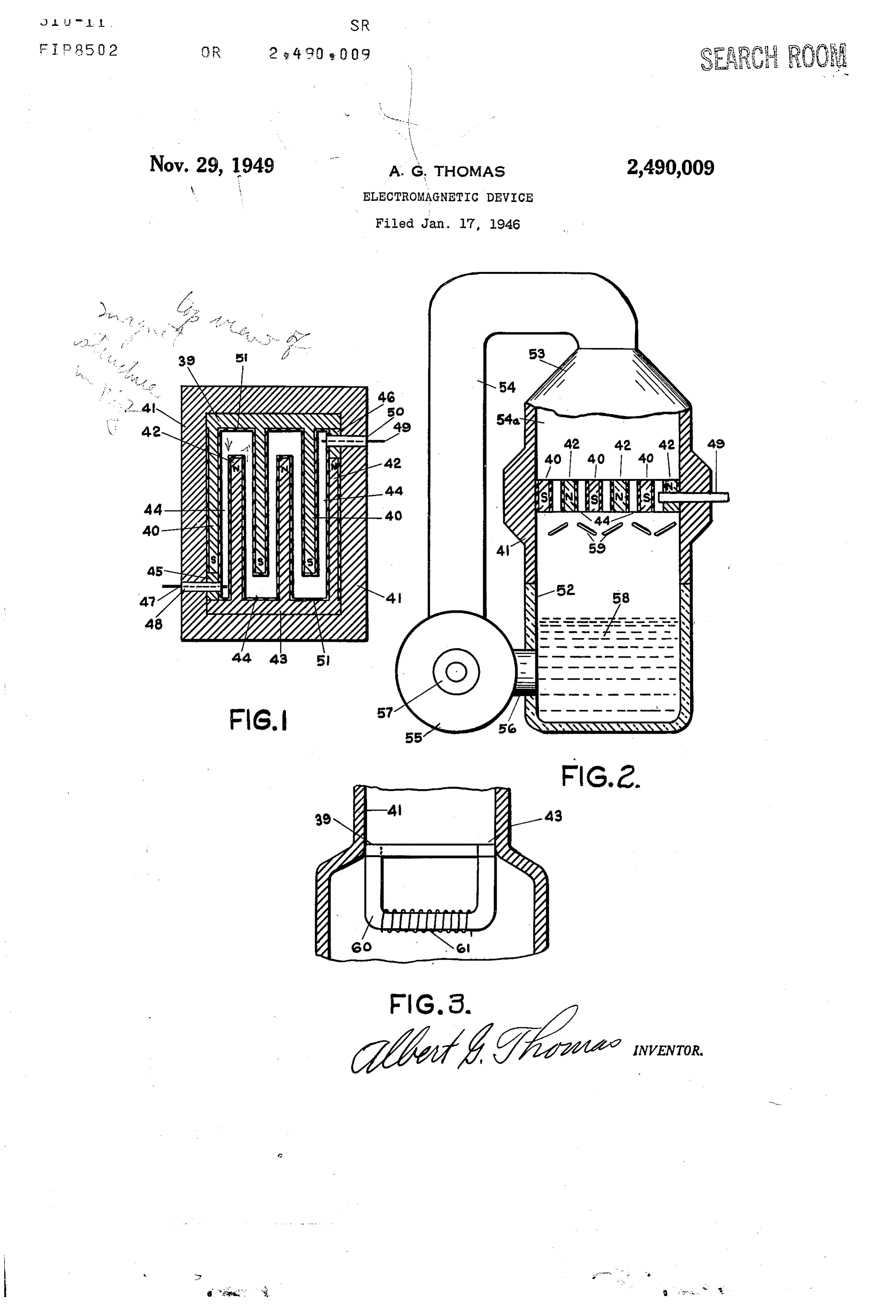
This invention relates to electrical devices and rial which may be of insulating char-acter. Elec h-as particular reference tc homopolar or «acylic trode or conductor 41 passes through insulating generators and motors. bushings 48 nested in openings in I“band 4| and For electro-plating and for other purposes it block 45. This electrode extends into channel 44 is advantageous to use continuous unidirectional to make contact with an electrolyte passing current substantially free from ripple.. In order _ through the channel. Similarly, electrode 49 eX to obtain current of this kind it has, heretofore, tends into the other end of channel 44, through been necessary to use batteries, elaborate filter insulating bushing 50. These bushings ñt tightly systems, or generators having complicated com around the conductors to prevent leak-age. mutating devices. 10 Insulating coating 5| is placed over the surfaces It is an object, therefore, to provide a genera of the magnets and the inner surface of band 4| tor of relatively simple construction that will in order to prevent short circuiting. This coat produce continuous direct current Àwithout ap ing may comprise an enamel, varnish, or equiva preciable ripple. lent material.
A further object is to provide a continuous cur 15 The composite magnet comprising band 4| and rent; electrical generator or motor which will not pole pieces 40 and 42 is preferably of permanent require brushes. , type, made of Alnico or similar material although An additional object is the provision of la con it lcould be an electro-magnet. The poles 42 are tinuous current generator using -a moving fluid of like sign and tpoles 40 are of opposite sign. as a generating element. 20 Magnetic flux -will therefore extend from pole to Another object is the provision of a generator pole as indicated lby the arrows, the flux return in which a plurality of electromotive forces de being through the magnet A‘base elements 39 and veloped in a conductor or conductors will add to 43 and band 4| which forms part of the casing. produce the total output electromotive force, The lower part of the casing 52 is attached to without commutation. 25 band 4| and is preferably made -of insulating ma Other objects .will appear in the following de terial such as ceramic, wood, plastic or the like. scription. The upper casing has flared portion 53 to which In the drawings: pipe 54 leading from pump 55, of any suitable Figure 1 is a plan view Vof interleaved magnetic kind, is attached. Inlet pipe `56 leads from cas ñeld elements attached to a casing of a fluid type 30 ing or vessel 52 to the pump. The pump may be continuous current generator. driven by pulley 51 or otherwise. Pipe 54 and Figure 2 is a front elevation in part section, of upper casing 53 may be of glass or other insulat a continuous current generator incorporating the ing material, if desired. The ñuid can be dropped magnetic ñeld elements of Figure 1 and a fluid by gravity from pipe 54 into chamber 54a to pumping system. 35 cause separation, for insulation purposes, or it Figure 3 is a fragmentary elevation, in part can be forced under pressure. The magnetic section, showing a modified ñux return for the ñeld elements can extend to the pump if desired. magnet poles, for the device of Figure 2. 'I‘he magnet poles are -preferably arranged in In Figures 1 and 2, iron or steel magnet 39 a horizontal plane as indicated in Figure 2 and having a plurality of elongated pole pieces 4u, 40 bailles 59 may be arranged beneath channel 44 is integral with or attached to heavy band 4| of so that fluid passing downward through the chan similar material, prefer-ably. Magnet 43, which nel will be broken into discontinuous portions to may be considered as a part of magnet 39, has prevent electrical connection between that fluid pole pieces 42 extending between the other pole and the supply of fluid 58 in vessel 52. This fluid pieces as shown, to form continuous channel 44. 45 may be mercury or any electrically conducting This channel is relatively narrow except for the liquid. - spaces near the pole rends which spaces may be In operation, .pulley 51 of pump 55 is rotated wider in order to distribute the flux to better by means of a driven belt, not shown, so that advantage, although this is not essential. Fur mercury or 'other iiuid 58 is drawn through pipe thermore, the pole pieces may, if desired, be of 50 56 and is forced through pipe 54 and down tapered dimensions in order to produce more or through channel 44 at relatively high velocity. less uniform magnetic ñux traversing the chan The conducting ñuid passing through the mag nel from pole to pole. netic ñeld or fields between the magnet poles The magnets 39 and 43 are separated by blocks generates an electromotive force or forces directed 45 and 4B of brass. or other non-magnetic mate 55 along the length of channel 44, as may be seen
Page 3
by viewing the flux directions indicated by the minal in said space adjacent one end thereof, arrows. I have found that appreciable potential another contact terminal in said space adjacent may be generated -by flow of a conducting ñuid the other end thereof, a conduit for fluid sur across a magnetic field. The current can be rounding said magnet, a reservoir for said fluid utilized by connecting electrodes 41 and 49 in a connected with said conduit, and pump means suitable circuit. for withdrawing fluid from said reservoir and The greater the velocity of flow of the fluid the forcing it through said space in a direction sub greater will be the potential generated, and simi stantially at right angles to the magnetic fields larly, the stronger the magnetic ñeld the greater between said fingers.
will .be the potential. 10 2. In an electrical device, a magnet having one If desired, the discharge from channel 44 could pole comprising a plurality of spaced substan be collected in buckets, traps or the like and could tially parallel elongated magnetizable fingers and be periodically dumped to prevent connection having the other pole comprising a plurality of with liquid 58. While a liquid is shown, an ion similar fingers interleaved with said first named ized gas or vapor could be used and electrical 15 ñngers and oppositely directed with respect means for ionizing the vapor could be included. thereto, said fingers being of proper dimensions The liquid that drops into chamber or vessel to form a continuous space from one end finger 52 is recirculated by the pump and a certain to another end finger, a contact terminal in said amount of cooling will take place in pipe 54 but space adjacent one end thereof, another contact special means such as a water b-ath or forced ven 20 terminal in said space adjacent the other end tilation could be employed. This generator will thereof, a conduit for iiuid surrounding said mag provide a, potential and -current virtually without net, a reservoir for said iiuid connected with said ripple. conduit, pump means for withdrawing fluid from The ends of the magnets could be rounded and said reservoir and forcing it through said space the channel can be of any desired pattern. A 25 in a direction substantially at right angles to series of circular channels could be used, with a the magnetic fields between said ñngers, and separate pump and ñuid supply for each channel, means between said magnet and said fluid reser if necessary. The electromotive forces developed voir for preventing continuous iiow of said fluid. in each could be connected in series by suitable 3. Same as in claim 1, said magnet compris conductors. A plurality of magnetic units as 30 ing a part of said conduit.
illustrated could be connected electrically in 4. Same as in claim l, said reservoir compris series, care being taken to prevent short circuits. ing insulating material.
The iiux return for the magnet poles is shown 5. Same as in claim l, and means between said as being coplanar but the return can be placed magnet and said pump for preventing continuous above or below the magnet poles and can be 35 flow of said fiuid.
apertured to allow passage of the liuid. ALBERT G. THOMAS. Vessel or chamber 54a can be of the same cross section as the pattern of channel 44 in order to REFERENCES CITED define the liquid conductor to better advantage The following references are of record in the and to prevent circulating currents. 40 file of this patent:
As shown in Figure 3, the flux return between magnet poles 39 and 43 is through iron or steel UNITED STATES PATENTS bar 60 which may loe wound with magnetizing Number Name Date coil 6|. This coil can be supplied with current 957,242 Noeggerath ______ __ May 10, 1910 from an external source or it can be connected in 1,196,511 Borger __________ __ Aug. 29, 1916 circuit with the electrodes 41 and 49 (Fig. 1). 2,106,842 Hague ____________ __ Feb. 1, 1938 The fluid may ñow around element GU and coil 6|. 2,302,983 Swallow __________ __ Nov. 24, 1942 Many other arrangements and changes of de 2,412,247 Bohn ____________ __ Dec. 10, 1946 tail are possible without departing from the broad principles disclosed by this invention. FOREIGN PATENTS What I claim is: Number Country Date 1. In an electrical device, a magnet having 7,670 Great Britain _________ __ Of 1902 one pole comprising a plurality of spaced sub 103,706 Germany ________ __ June 26, 1899 stantially parallel elongated magnetizable fingers OTHER REFERENCES and having the other pole comprising a plurality of similar fingers interleaved with said first Theory and Calculation of Electrical Appa named fingers and oppositely directed with re ratus, by C. P. Steinmetz, pages 450 to 453, First spect thereto, said ñngers being of proper di edition, published 1907, McGraw-Hill Book Co., mensions to form a continuous space from one Inc., New York, New York. end finger to another end finger, a contact ter 60
Provenance
- Collection
- Cited prior art
- Original PDF
- patentimages.storage.googleapis.com →
- Filed
- 1946-01-17
- Pages
- 3
- Method
- pdftotext (the PDF's own text layer) + pdftoppm 300dpi page scans
- Source
- Google Patents bibliographic record
- Granted
- 1949-11-29
- Inventors
- Albert G Thomas
- Transcribed from
- patentimages.storage.googleapis.com →