patent · US3749953
Ventilated dynamoelectric machines
31 July 1973
Page 1 — bibliographic record
United States Patent (19) (11 3,749,953 Baumann et al. (45) July 31, 1973 S4 VENTILATED DYNAMOELECTRIC 2,778,958 1/1957 Hamm .................................. 310/63. MACHINES 2,783,398 2/1957 Haas........... ... 310158 3,272,136 9/1966 Franzen................................ 310/52 75) inventors: Frederick W. Baumann, Scotia;
George M. Rosenberry, Jr., Elnora, Primary Examiner-R. Skudy both of N.Y. Attorney-Vale P. Miles et al.
(73) Assignee: General Electric Company,
Schenectady, N.Y. 57 ABSTRACT (22 Filed: Feb. 24, 1972 A dripproof (open ventilation) dynamoelectric ma (21) Appl. No.: 228,891 chine is improved by the addition of an auxiliary fan and fan enclosure of totally enclosed design to either or 52 U.S. Cl................................................... 310/62 both ends of the basic dripproof machine. The fan and its associated enclosure direct at least a majority of the 51) Int. Cl. ............................................. H02k9/06 air passing into the fan enclosure through the adjacent 58 Field of Search ................... 310/62, 63, 58, 52, dripproof end shield to the end turn cavity of the dyna 310/85, 89 moelectric machine for enchanced cooling of the stator
winding end turns. After passing over the end turns, the airflow is exhausted by the end shield curvature axially
UNITED STATES PATENTS along the outer periphery of the machine to flow be 2,615,937 - 10/1952 Ludwig................................. 310/63 tween a plurality of cooling fins extending outwardly 2,488,365 1 1/1949 Abbott.................................. 310/62 from the stator frame to further cool the machine. 3,610,975 10/1971. Onjanow............................... 310/63 2,716,195 8/1955 Anderson.............................. 310/63 3 Claims, 3 Drawing Figures
WSSAWXWSXXYYXV S3 SS (rS 22.e4/ YN
SNSNNNNNS
NSS N S.
22 NSN
4' SN SQSQNSQSSSNSN
SXSW SS
Yeacea
Page 2
Drawing sheet — no readable text.
Page 3
Drawing sheet — no readable text.
Page 4
Drawing sheet — no readable text.
Page 5
VENTELATED DYNAMOELECTRIC MACHINES frame. Because the rotor fans serve to draw the air into BACKGROUND OF THE INVENTION the machine, as well as exhaust the air along the frame, the volume of air passing through the motor is limited
The present invention relates to dynamoelectric ma to a fan size determined by the end turn region (not chines, and more particularly to dynamoelectric ma withstanding the use of curved fan blades at opposite chines having superior ventilation produced by the uti ends of the rotor to enhance air flow). Although air lization of an auxiliary fan and fan enclosure on at least flow through a machine can be enhanced by additional one end of a dripproof machine for increasing air flow serial fans, such fans typically have necessitated expen through the adjacent end turn cavity of the machine. sive redesigns of existing machines and the mainte Among the design problems related to dynamoelec 1 O nance of large inventories of unique parts. tric machines, none is more significant than the prob The present invention brings relief to both of these lem of generated heat, i.e., Joulean heating of machine problem areas, i.e., cooling of end turns and reducing windings combined with heat produced by hysteresis attendant costs, by combining with a ventilation system and eddy currents within magnetic members of the ma for a dripproof motor (which emphasizes end turn cav chine cause operating temperatures to increase as in 15 ity cooling) an inexpensive external auxiliary fan and creased power is drawn from, or supplied to, the ma fan enclosure adapted to direct a majority of the air chine. Dissipation of the heat generated in this manner moved thereby into the associated end turn cavity for is required to prevent destruction of the electrical insu maximum heat dissipation prior to exhaust of the air lation of the machine and other undesirable phenom stream axially along the exterior of the finned stator ena which combine to reduce efficiency and cause fail frame. Furthermore, the auxiliary fan and casing of the ure. Thus, as attempts are made to increase the power present invention are adapted to be interchangeably input or output of such machines, a major concern be used in combination with dripproof and totally en comes the manner and efficiency of dissipating the heat closed machines without the requirement for the utili of operation. zation of specialized fan and enclosure designs adapted In the past, dynamoelectric machines have been of 25 solely for use on one or the other type machine. alternative totally enclosed (containing a fixed quantity It is therefore an object of the present invention to of circulating cooling fluid) or dripproof (that is, open provide a dynamoelectric machine having a new and to the external ambient atmosphere) designs. Air improved ventilation system.
cooled totally enclosed machines commonly combine It is a further object of the present invention to pro means for circulating a fixed volume of fluid within the 30 vide a dripproof dynamoelectric machine having a ven machine enclosure (for carrying heat from the heat tilation system which provides increased flow of cool generating elements to the frame and other external el ing air into the end turn cavities. ements of the machine) with an external fan adapted to It is still another object of the present invention to direct a flow of atmospheric air across the frame and/or 35 provide an auxiliary external fan and enclosure which end shields of the machine to transfer the heat there are capable of being used in combination with pres from into the atmosphere. Air-cooled dripproof ma ently available dripproof machines and totally enclosed chines, on the other hand, commonly incorporate a sin machines without the requirement for a variation in the gle internal fan, or a plurality of internal fans associated design of such fans and enclosures. with the rotor element for drawing atmospheric air into 40 It is a further object of the present invention to pro the machine and into direct contact with the heat pro vide a dripproof machine ventilation system incorpo ducing elements thereof to transfer heat by convection rating a first rotor fan disposed inside the machine cas to the air before subsequently expelling the heated air ing and a second fan disposed externally of the machine back into the atmosphere. Prior art dripproof machines which together operate serially upon a given air flow also have been provided with auxiliary fan elements through the machine.
disposed on at least one end of the machine to increase 45 SUMMARY OF THE INVENTION the flow of cooling air through the machine in coopera tion with the internal fan elements. In order to accomplish the foregoing (as well as fur Although most air cooled dripproof motor ventila ther objects which will become apparent hereinafter), tion techniques pass the main air stream axially through the present invention, in one embodiment thereof, uti the motor interior while totally enclosed motors pass 50 lizes a machine of the dripproof variety having a pair the cooling air over the exterior of the motor frame, a of opposed internal fan members associated with the number of "hybrid' designs, e.g., such as the design il machine rotor. The internal fans are located in end turn lustrated in Dunn, Jr. U.S. Pat. No. 3,383,530, have cavities between the machine's stator and end shield at been proposed wherein a majority of the air is passed axially opposite ends of the machine. Each internal fan axially down the finned outer shell of the motor with a 55 is designed to pass cooling air through its associated minor quantity of air also being bled into the end turn end turn cavity from an entrance to a radially located region through a selectively apertured partition to exit before passing the air axially between fins protrud gently scrub the end turns. While such motor designs ing outwardly from the stator frame. To one or both tend to reduce the abrasive effect of particulate mate 60 ends of the machine, as described, is added an external rial in the air stream upon the end turn insulation, air fan driven by rotation of the rotor, and a fan enclosure flow through the end turn region is limited. Similarly, having an air intake and exhaust adapted respectively other dripproof motors, e.g., in U.S. Pat. application to draw atmospheric air into the enclosure and direct Ser. No. 87,1 17, now a U.S. Pat. No. 3,643,119 filed in at least a majority of the air into the associated end turn the name of A.F. Lukens, have been proposed wherein 65 cavity through orifices in the machine end shield. The the entire cooling air stream is drawn through the end fan and enclosure are to be designed so as to be readily turn cavities of the machine before being axially ex mounted upon dripproof machines as well as upon to hausted along the finned outer surface of the machine tally enclosed machines of the same frame size.
Page 6
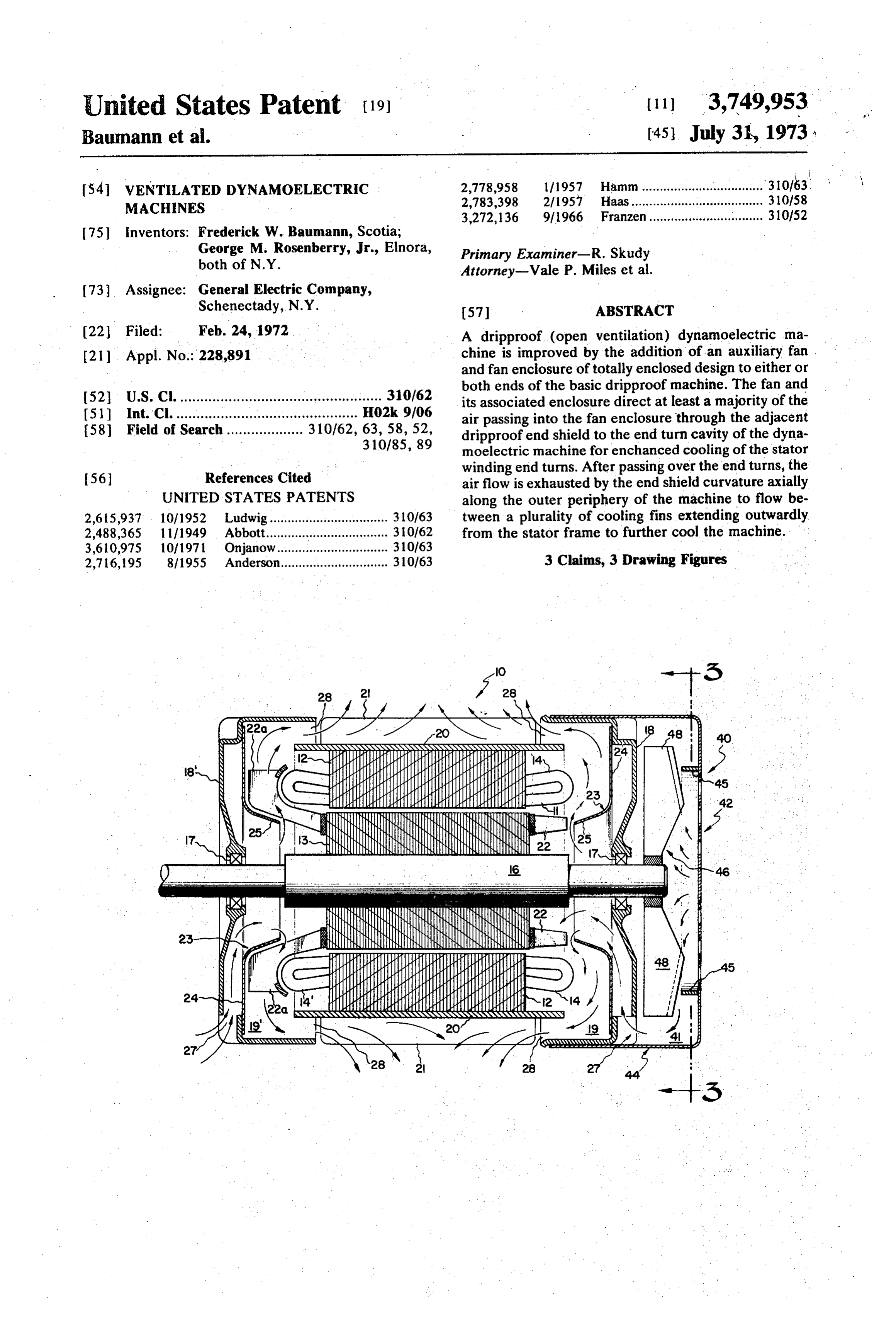
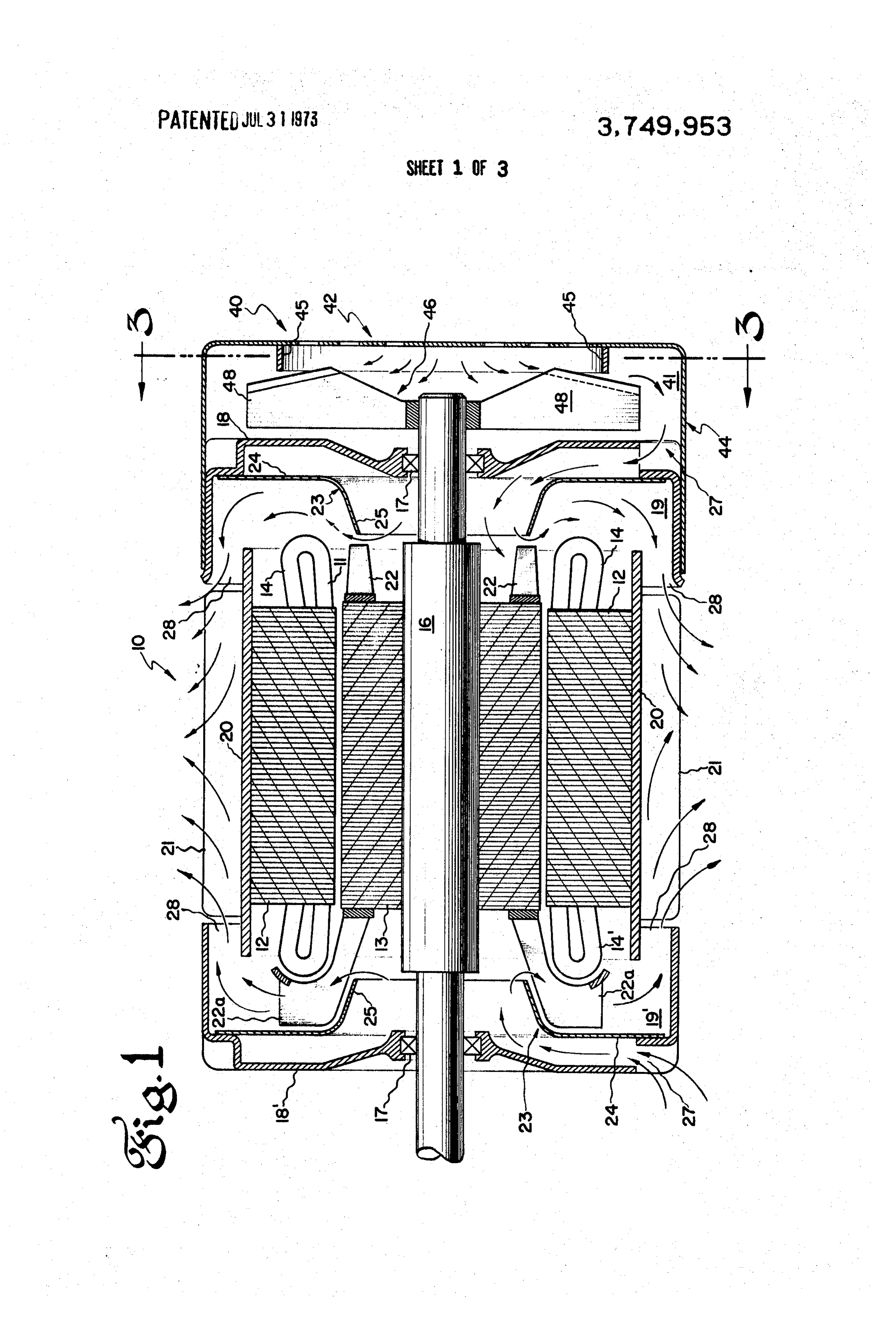
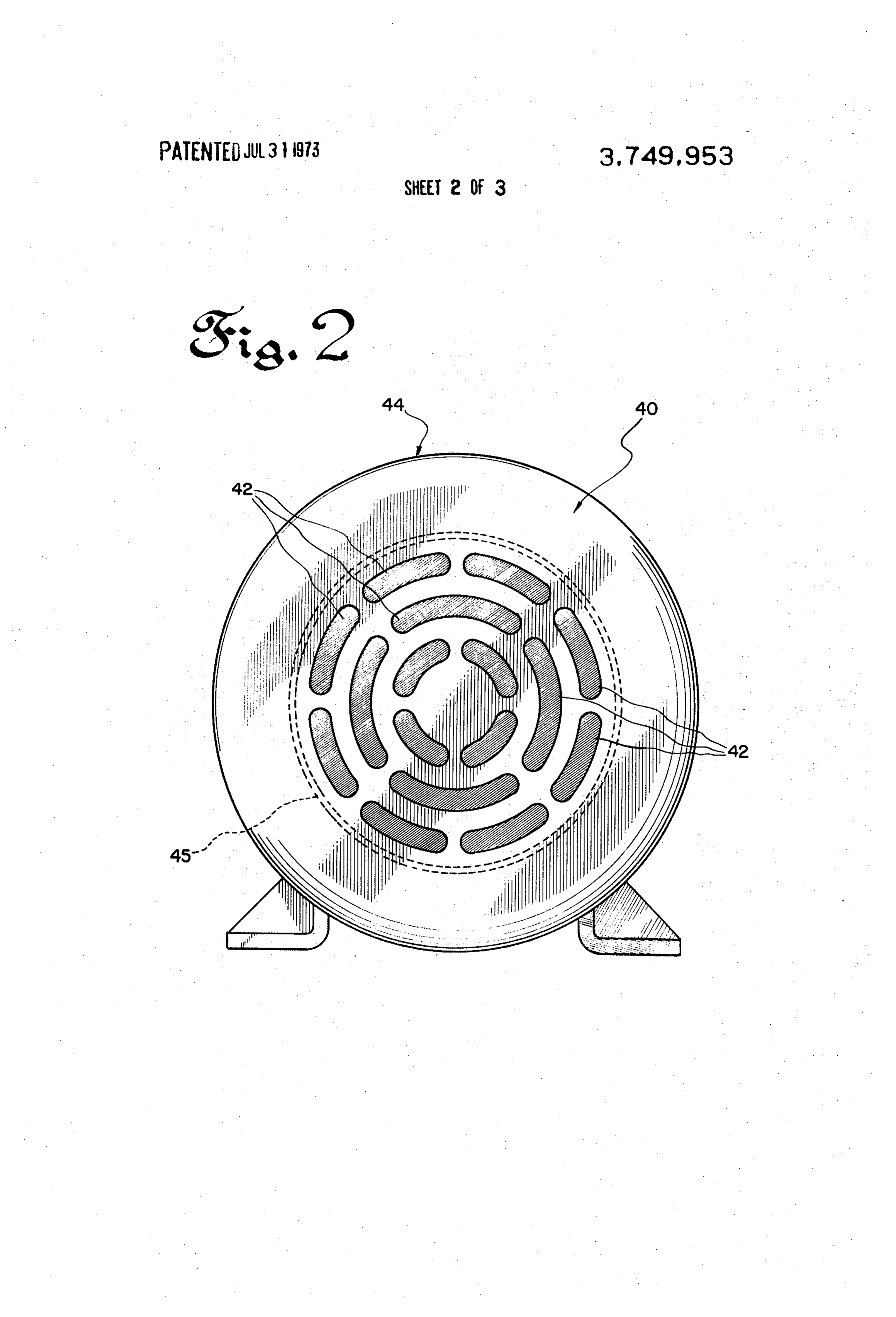
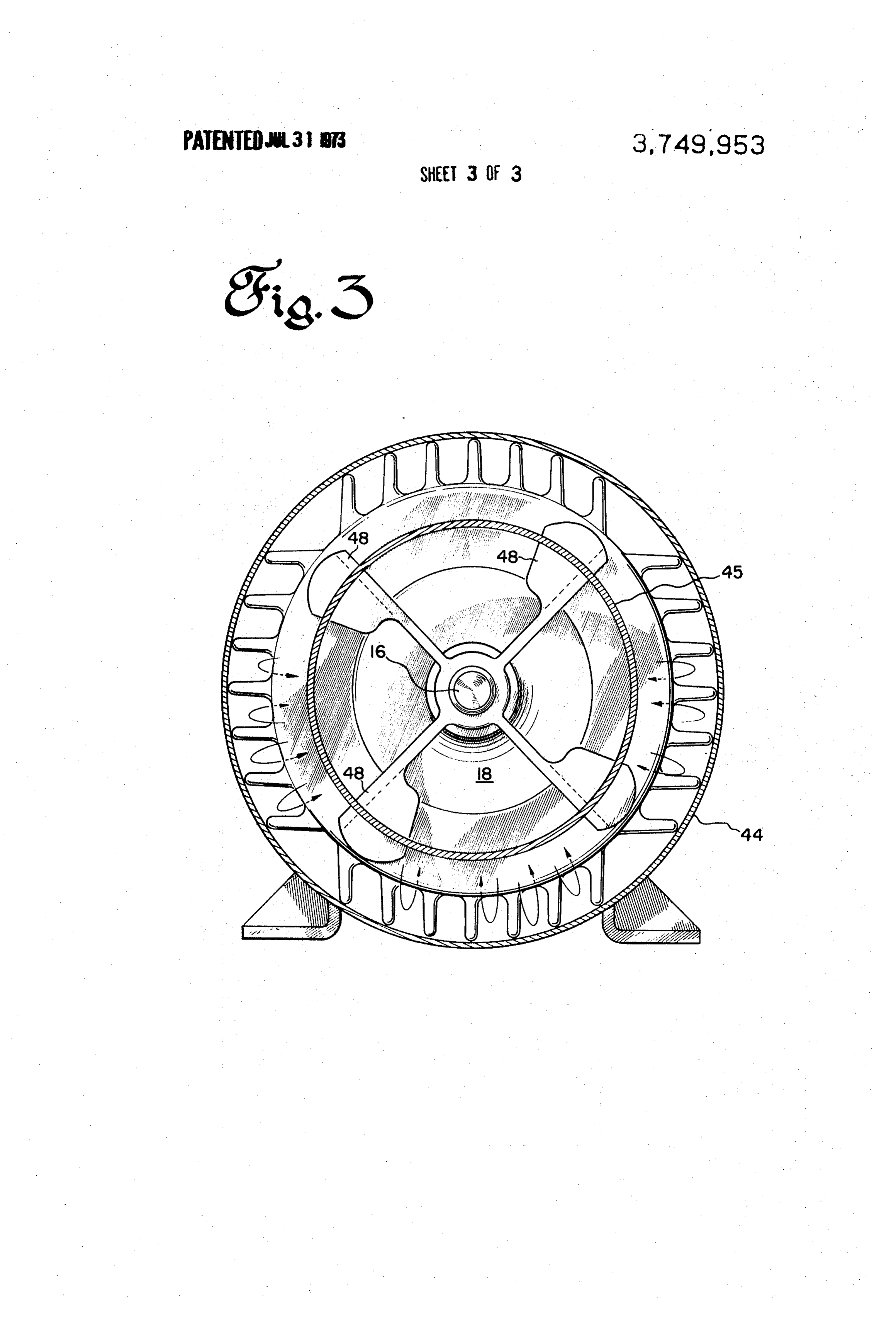
The present invention will be more particularly de wardly flaring periphery 24 and a truncated conical scribed which:
hereinafter in conjunction with the drawings in center section 25, is adapted to guide air into the radi FIG. 1 is an axial section view of a motor incorporat ally central portion of the motor proximate shaft 16 ing the improved ventilation system of the present in (and fan blades 22) from a plurality of orifices 27 dis vention, posed along the bottom and sides of dripproof end FIG. 2 is an elevation of the fan cover, and shields 18 and 18'. An exhaust opening 28 is provided FIG. 3 is an elevation of the motor end shields taken for passing the air from the end turn cavity 19 axially along lines 3-3 of FIG. 1. along the outer periphery of frame 20 and past cooling fins 21 into the atmosphere. To this extent, the flow of
DESCRIPTION OF A PREFERRED EMBODEMENT 10 cooling air through the end turn cavities of the motor A dripproof induction motor 10 incorporating ele is similar to such applications in the prior art. ments of the present invention, is depicted in FIG. 1 In departure from the prior art, at the opposite drive and generally includes an annular stator 12 circumfer 40 end of the motor is applied a particular fan enclosure entially disposed about a cylindrical rotor 13 supported 15 having multiperferate apertures, identified by refer upon a rotatable shaft 16 mounted within bearings 17. ence numeral 42, for the admission of air to the fan Except for the motor ventilation, the motor is conven space 41 defined between the fan enclosure 40 and end tional in design with rotation of the squirrel cage rotor shield 18. The fan enclosure 40 includes a cylindrical being effected by the magnetic fields generated by cur wall 44 or other alternative baffle arrangement for rent flow through stator windings 11 extending axially 20 guiding the air flowing out of the fan space into the as through slots (not shown) formed along the radially sociated end turn cavity 19 through orifices 27. Wall 44 inner surface of stator 12. also serves to join the fan enclosure 40 to the basic Enclosing the ends of the rotor and stator are a pair alsodripproof motor 10, and is designed to be applicable of end shields 18 and 18", which, together with the sta to enclosed motors of the same frame size. tor, form end turn cavities 19 and 19' enveloping end 25 Upon an extended portion of rotor shaft 16 is turns 14 and 14". Circumferentially surrounding the sta mounted an auxiliary fan, illustrated as a radial fan 46 tor is a cylindrical frame 20 which carries a plurality of having a plurality of fan blades 48. The auxiliary fan is outwardly extending cooling fins 21. Part of the heat adapted to move very large quantities of air and, in produced within the stator during the operation of the combination with the fan enclosure, moves such quan motor is conducted to fins 21 through frame 20 to be 30 tities of air through fan space 41 into end turn cavity transferred by convection to air flowing axially be 19 through orifices 27. Due to the absence of clearance tween the fins. The foregoing basic motor structure is restrictions upon the size of the blades of fan 46 (which similar to the motor described in heretofore mentioned limitations do apply to fan blades 22), the auxiliary fan Lukens U.S. Pat. No. 3,643,119. can be designed to move as much air as is desired into Having thus described the typical basic motor struc 35 the associated end turn cavity for the purpose of cool ture, the new and improved ventilation system of the between ing end turns 14. An annular plate 45 also is provided present invention will now be described. As discussed flow the fan and fan enclosure to limit the back above, a critical problem of motor (and other dynamo of air in the fan enclosure. It can thus be seen that electric machine) design has been means for cooling the addition of this auxiliary fan produces a substantial the end turns 14 during operation of the machine. 40 motor. enhancement of the cooling capacity of the dripproof Cooling fins 21 are adapted to carry off much of the heat generated by the stator, but the fins are incapable Because no auxiliary fan normally is employed at the of cooling the end turns due to the position and orienta drive end of the motor, e.g., because of design limita tion of the latter. Therefore, it is desirable to make pro tions commonly associated with the drive end of a mo vision for the passage of a large quantity of cooling air 45 tor, the motor of the present embodiment of the inven through the end turn cavities in such a way as to carry tion preferably is characterized by enlarged rotor fan off the end turn heat by means of convection. While blades 22a which extend axially into end turn cavity 19' prior attempts at increasing air flow through the end before sweeping radially outward to overlie the ends of turn cavity have met with limited success, the present end turns 14'. The curved rotor fan blades significantly invention incorporates elements for greatly increasing 50 enhance air flow in a radial direction (i.e., relative to this flow thereby greatly enhancing cooling of the end the nominal rotor diameter fan blades 22 illustrated at turns. Although the ventilation system disclosed in FIG. the opposite drive end of the rotor) and preferably are 1 is particularly disclosed as applied to the dripproof utilized when design restrictions inhibit use of an auxil motor arrangement, it is significant, i.e., from a parts iary fan at the drive end of the motor. However, if such design and inventory standpoint, that the added cooling 55 design restrictions do not apply in a particular situa elements of the present invention may be alternatively fan tion, it would be possible to incorporate an auxiliary used at the drive end of the motor in association with for the cooling of totally enclosed motor configu nominal diameter rotor blades.
rations.
Assuming that the left-hand side of the motor illus As can be seen from the fan cover of FIG. 2, air flow trated in FIG. 1 is the drive end thereof, and the right 60 ing into the opposite drive end of the motor is drawn hand side is the opposite drive end, the ventilation sys through a plurality of apertures 42 approximately cen tem disclosed therein is arranged as follows. Referring trally disposed along the face of the fan cover remote first to the opposite drive end, a plurality of nominal from the motor. The air then is impelled radially out rotor diameter fan blades 22 cast upon the end rings of ward toward cylindrically shaped wall 44 abutting rotor 13 serve to move air through the end turn cavity 65 against the outer periphery of end shield 18 to be di in the directions shown by the arrows. A baffle 23 dis rected into end turn cavity 19 through orifices 27 in the posed within the end turn cavity, and having an out end shield. Because end shield 18, illustrated in FIG. 3, is a conventional dripproof end shield inhibiting entry
Page 7
S 6 of water falling at an angle of less than 15 from verti chine further reducing parts inventory. cal, the only orifices 27 through end turn cavity 19 are It is to be noted that the present invention has been located along the sides and bottom of the end shield. described as applied to squirrel cage induction motors. Although the entire air stream entering fan enclosure The concepts of the invention, however, are equally ap 40 is illustrated in FIG. 1 as passing through end turn plicable to any dynamoelectric machine. It is therefore cavity 19 before passing axially along the motor frame, intended that the appended claims shall cover all such small quantities of air flowing into the fan enclosure modifications as do not depart from the true scope of also can be diverted from the end turn cavity to flow the invention.
directly down the finned stator frame by providing ap What is claimed as new and desired to be secured by ertures (not shown) through end shield 18 in radial reg 10 Letters Patent of the United States is: istration with stator fins 21. The number and the size 1. A dynamoelectric machine comprising; a stator of the apertures, however, should be such that a major having a stator winding including winding end turns ex ity, and preferably in excess of 70 percent by volume, tending from opposite ends of the stator, a rotor rotat of the air flow into fan enclosure 40 passes through the ably mounted within the stator, a stator frame circum end turn cavity adjacent the fan enclosure. 15 ferentially disposed about said stator, end shields dis In operation, current is fed to stator windings 11 of posed proximate each end of the stator to define end FIG. 1 causing rotation of the rotor 13 by means of the turn cavities respectively between the stator ends and magnetic flux forces thus created. This process also said shields, each of said end shields having non produces electrical and magnetic heating within the symmetrical intake orifices therein for admitting air to stator which is conducted to cooling fins 21 for transfer 20 the end turn cavity associated therewith and defining to air passing between the fins. In accordance with this with said frame an exhaust opening radially outward invention, electrical heating of end turns 14 is counter from said stator for passing air out of said cavity axially acted by means of the convective heat transfer to the along the outer periphery of the stator frame, first fan air directed thereacross. At the opposite drive end of means comprising two sets of rotor mounted fan blades the motor, large quantities of cooling air are drawn into 25 (22 and 22a), each said set of fan blades being disposed fan space 41 through apertures 42 by the rotation of respectively within one of said end turn cavities for fan 46 and the air is directed by fan enclosure walls 44 moving air therein, a fan enclosure disposed in a posi out of the fan space into end turn cavity 19 through ori tion axially spaced outward from at least one end shield fices 27 situated along the sides and bottom of the drip and, together with said one end shield, defining a fan proof end shield. The air then is directed by baffle 23 space, said fan enclosure having an aperture for passing toward the radial center to the rotor and into coopera air therethrough into said fan space, and said fan enclo tion with rotor fan blades 22 whereat the velocity of the sure further having wall means for directing at least a air is enhanced by the rotor fan blades prior to flowing majority of said air out of said fan space and into the across the radially inner surface of end turns 14. Subse end turn cavity associated therewith through said ori quently, the air exits through exhaust opening 28 to 35 fices in said end shield, and second fan means disposed flow axially between cooling fins 21 to accept heat within said fan space for moving said air through said from the stator frame. aperture into said fan space and thence into coopera At the drive end of the motor depicted in FIG. 1, the tion with said air directing means and said first fan direction of the air flow through end turn cavity 19" is caS substantially the same as air flow in end turn cavity 19, 40 2. The dynamoelectric machine of claim 1 in which however, the volume of the air flow in end turn cavity said first fan means includes a plurality of nominal 19' is reduced by the absence of the auxiliary fan and rotor diameter fan blades mounted at one end of said fan enclosure. rotor and a plurality of enlarged rotor fan blades As stated hereinbefore, in addition to enhancing the mounted on the other end of said rotor, said enlarged air flow through the end turn cavity of dripproof mo 45 fan blades being formed to extend axially into their as tors, the auxiliary fan of the present invention is alter sociated end turn cavity (19') and to also extend radi natively applicable to cool by convection the external ally outward to overlie the ends of the stator end turns surfaces of totally enclosed motors. It can thus be seen adjacent thereto, and wherein said second fan means that this interchangeability substantially reduces the includes a radial fan mounted upon the shaft of said requirement for a large parts inventory to be kept for 50 rotor outboard from the rotor diameter fan blades of the application of auxiliary fans to closed and open mo the first fan means.
tors. Additionally, while the present embodiment has 3. A dynamoelectric machine according to claim 1 disclosed enlarged rotor fan blades 22a at the drive end wherein the entire air streams passing through said ori of the machine, it may be seen that the application of fices are passed respectively into the end turn cavities the present invention does not always require these en 55 before being directed toward one another along the larged blades; and the nominal rotor diameter rectan outer surface of the frame of the machine. gular blades 22 may be used at both ends of the ma k k s
Provenance
- Collection
- Cited prior art
- Original PDF
- patentimages.storage.googleapis.com →
- Filed
- 1972-02-24
- Pages
- 7
- Method
- pdftotext (the PDF's own text layer) + pdftoppm 300dpi page scans
- Source
- Google Patents bibliographic record
- Granted
- 1973-07-31
- Inventors
- F Baumann; G Rosenberry; General Electric Co
- Transcribed from
- patentimages.storage.googleapis.com →