patent · US5992397
Combustion enhancing apparatus and method
30 November 1999
Page 1 — bibliographic record
United States Patent (19) 11 Patent Number: 5,992,397 Hideaki et al. (45) Date of Patent: Nov.30, 1999
54) COMBUSTION ENHANCING APPARATUS 4,308,847 1/1982 Ruizzo .................................... 123/536 AND METHOD 5.243,950 9/1993 Dalupan .................................. 123/536 5,271,370 12/1993 Shimada et al. ... 123/25 A 76 Inventors: Watase Hideaki, Blk 135 Serangoon 5,694,888 12/1997 De Lima ................................. 123/1 A Ave 3, #07-03, Chiltern Park,
Singapore, 556114; Dalupan Romulo
Vallejos, Sunset View Condominium, Primary Examiner Marguerite McMahon 2230 Roxas Boulevard, Pasay City, Attorney, Agent, or Firm-Cesari and McKenna, LLP
Philippines, 1300; Tan Slew Lay, Blk 131 # 05-1335, Bedok Reservoir Road, 57 ABSTRACT
Singapore, 470131 A gas apparatus for internal combustion engine is disclosed in which recovered hydrocarbon gas vapors from the fuel 21 Appl. No.: 08/885,407 tank and the hydrocarbon with radical hydrocarbon gas 22 Filed: Jun. 30, 1997 Vapors from the crankcase, are mixed together with air and e a Vs alcohol with water Solution in an impeller mixing chamber (51) Int. Cl. ............................................... F02M 27/04 causing modified hydrocarbon gas Vapors and oxygen gas 52 U.S. Cl. ......................... 123/538; 123/573; 123/25 A Vapors to pass through an electronic ionizer producing 58 Field of Search ..................................... 123/572, 573, negatively charged pre-oxidized hydrocarbon gas vapors, 123/536, 537, 538, 1A, 25 A then fed through the air induction System to improve mass of air to mass of fuel ratio in an internal combustion engine.
56) References Cited A method for production of negatively charged pre-oxidized hydrocarbon gas vaporS is also disclosed.
3,989,017 11/1976 Reece ...................................... 123/536 33 Claims, 3 Drawing Sheets
Page 2
Drawing sheet — no readable text.
Page 3
Drawing sheet — no readable text.
Page 4
Drawing sheet — no readable text.
Page 5
COMBUSTION ENHANCING APPARATUS to mass of fuel ratio to enhance combustion in an internal AND METHOD combustion engine. In addition, the ambient air (N+O) with the negatively charged pre-oxidized hydrocarbon gas vapors
FIELD OF THE INVENTION
(HC+O) mix with the vaporized fuel in the combustion
The present invention relates generally to improving chambers contains more oxygen, creating greater expansion engine efficiency particularly the mass of air to mass of fuel of the pistons during the combustion process. After ratio, combustion thermal efficiency and reduction of carbon combustion, the exhaust emission contains lower counts of deposit accumulation in the combustion Systems of diesel, hydrocarbons (<HC), lower carbon monoxide (<CO), lower petrol and propane internal combustion engines. oxides of nitrogen (<NO), lower carbon particulates (<CP) This invention make use of recovered hydrocarbon gas with (CO), compound gas elements composed of carbon dioxide nitrogen dioxide (NO), sulfur dioxide (SO) and vapors vented from the fuel tank and blow-by hydrocarbon extra oxygen (O2).
with hydrogen gas Vapors vented from the positive crank case ventilation System of an engine. Here is the equation that shows what happens after These vented hydrocarbon gas vapors are mixed with air 15 combustion in an engine.
and passed into a liquid mixture in the apparatus, disasSo ciating the molecular chain of hydrocarbon gas vapors into methane and ethane gas vapors with Oxygen, which bubble out and then pass through a negative ionization process. The first objective of this invention is to provide an These newly produced gas vapors from the apparatus apparatus to recover normally lost hydrocarbon gas Vapor called negatively charged pre-oxidized hydrocarbon gas vented out into the atmosphere.
Vapors are then fed through the air induction System of an gasThe Second objective is to pass the recovered hydrocarbon vapors through a liquid mixture in the apparatus to form internal combustion engine to improve mass of air to mass of fuel ratio. ethane and methane gases associated with oxygen. 25 The third objective is to disassociate hydrocarbon gas
BACKGROUND OF THE INVENTION Vapors in the liquid mixture through the use of an impeller, The internal combustion engine is used to convert the octane resulting in a venting from the liquid Solution of the high chemical energy of fuel into heat energy and then to convert Vapors.
this heat energy into usable mechanical energy. This is adding fourth
The objective is to increase the oxygen ratio by achieved by combining the appropriate amounts of air and air flowing throughcharged negatively the pre-Oxidized hydrocarbon to the induction System of the engine. The fuel and burning the mixture in an enclosed cylinder at a fifth objective is to provide negatively charged pre-oxidized controlled rate.
hydrocarbon gas vapors, produce high expansion of pistons,
An average air/fuel ratio of good combustion for a petrol increase the engine power, Save fuel consumption, reduce engine is about 15 parts of air to 1 part of fuel by weight. the emission of hydrocarbon gas Vapors and achieve higher Diesel engines operate on a much wider air/fuel ratio, Since 35 efficiency of engine performance. air intake is not regulated on most diesel engines. The ratio The sixth objective is to improve the thermal efficiency of may range from about 20:1 to about 100:1. This fact, plus an engine by adding negatively charged oxygen into the the high compression of the diesel engine, makes it a fuel combustion chamber of an engine, causing a lower amount efficient engine. of oxides of nitrogen.
But the amount of oxygen may become insufficient due to 40 These and other objects of the invention will become different kinds of fuel grades and the quality of oxygen apparent in light of the accompanying Specification, claims, entering into the engine. These are Some factors that affect and drawings.
energy loSS in an internal combustion engine.
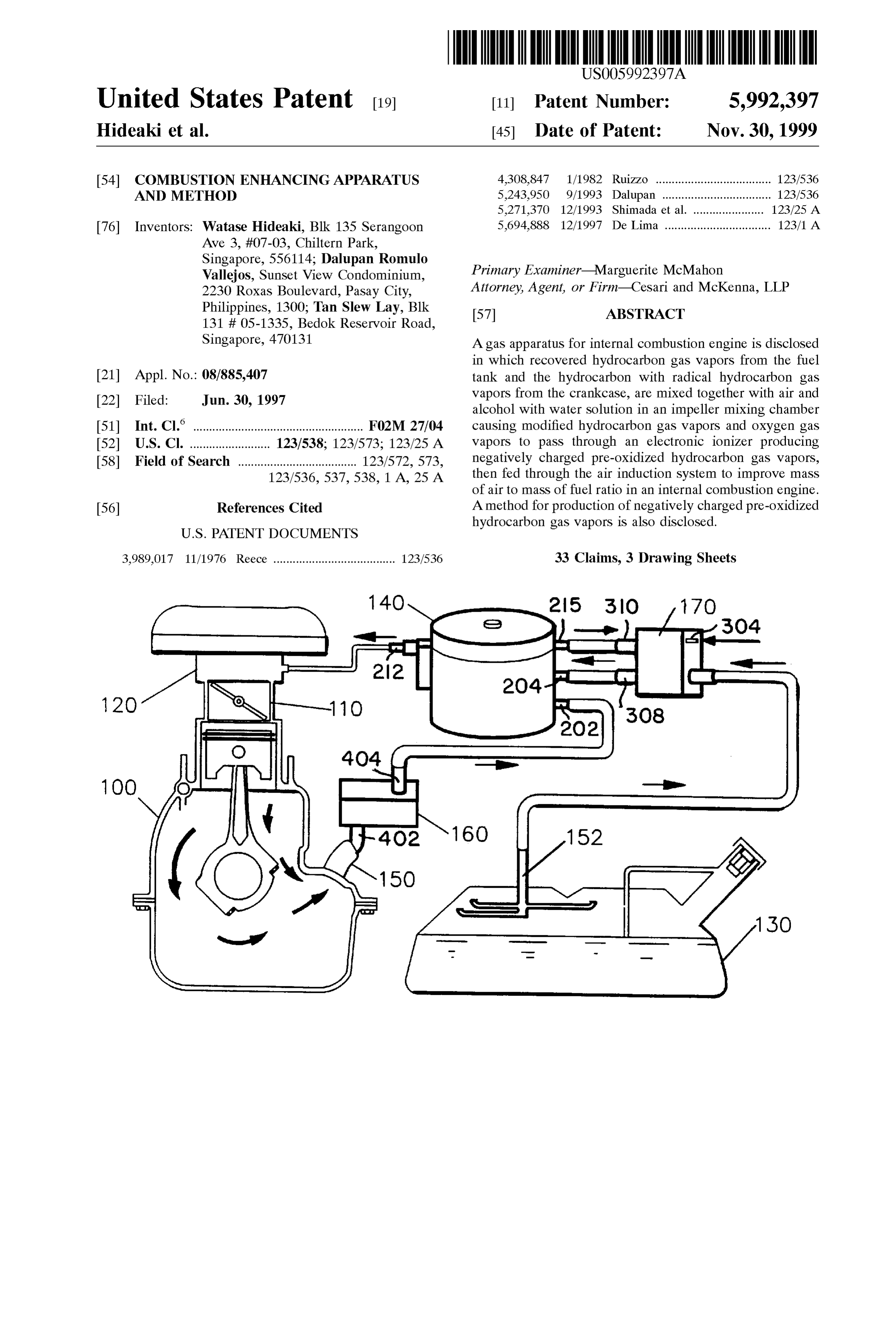
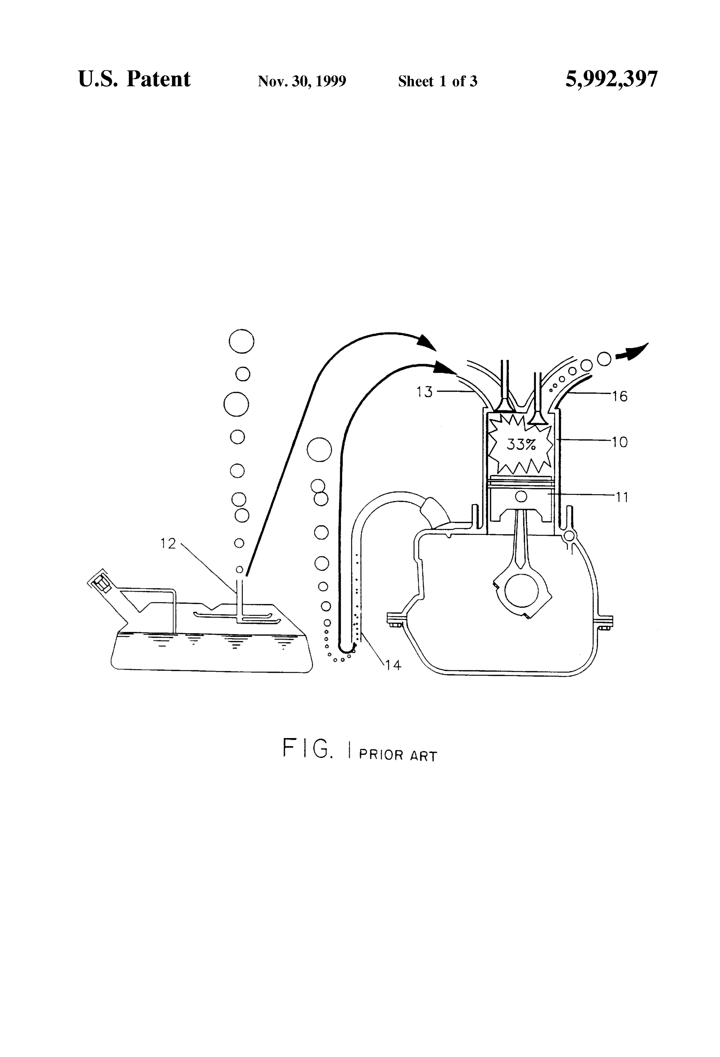
The efficiency of a typical existing internal combustion 45 SUMMARY OF THE INVENTION engine illustrated in FIG. 1, in converting the potential According to the invention, there is provided an apparatus energy in fuel to mechanical energy is only about 33%. Of producing negatively charged pre-oxidized hydrocarbon gas the available fuel energy in an engine, about one-third is Vapors comprising:
loSS, due to the following factors.
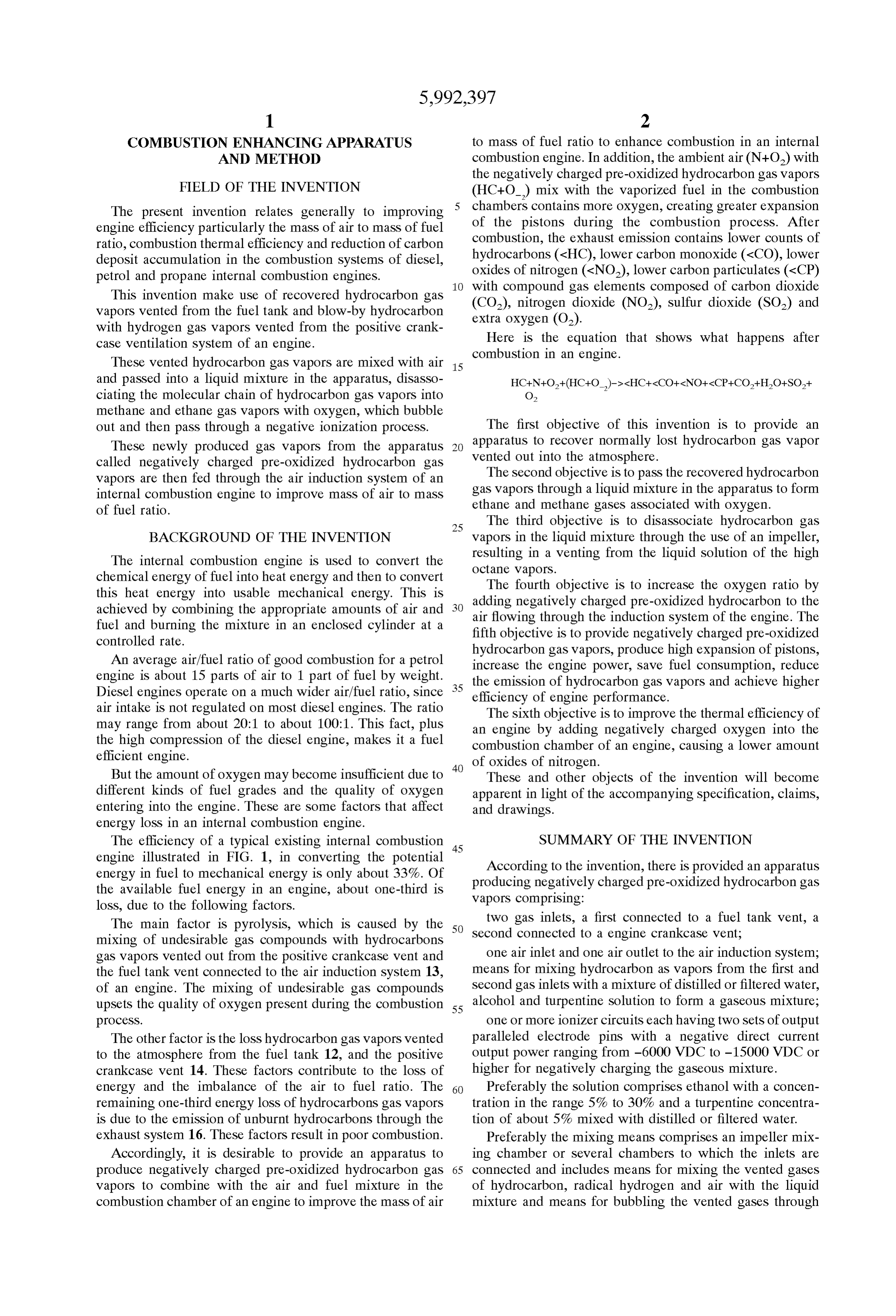
The main factor is pyrolysis, which is caused by the 50 two gas inlets, a first connected to a fuel tank vent, a mixing of undesirable gas compounds with hydrocarbons Second connected to a engine crankcase vent; gas vapors vented out from the positive crankcase vent and one air inlet and one air outlet to the air induction System; the fuel tank vent connected to the air induction System 13, means for mixing hydrocarbon as vapors from the first and of an engine. The mixing of undesirable gas compounds Second gas inlets with a mixture of distilled or filtered water, upsets the quality of oxygen present during the combustion 55 alcohol and turpentine Solution to form a gaseous mixture; proceSS. one or more ionizer circuits each having two sets of output The other factor is the loSS hydrocarbon gas vapors vented paralleled electrode pins with a negative direct current to the atmosphere from the fuel tank 12, and the positive output power ranging from -6000 VDC to -15000 VDC or crankcase vent 14. These factors contribute to the loss of higher for negatively charging the gaseous mixture. energy and the imbalance of the air to fuel ratio. The 60 Preferably the solution comprises ethanol with a concen remaining one-third energy loSS of hydrocarbons gas vapors tration in the range 5% to 30% and a turpentine concentra is due to the emission of unburnt hydrocarbons through the tion of about 5% mixed with distilled or filtered water. exhaust System 16. These factorS result in poor combustion. Preferably the mixing means comprises an impeller mix Accordingly, it is desirable to provide an apparatus to ing chamber or Several chambers to which the inlets are produce negatively charged pre-oxidized hydrocarbon gas 65 connected and includes means for mixing the vented gases vapors to combine with the air and fuel mixture in the of hydrocarbon, radical hydrogen and air with the liquid combustion chamber of an engine to improve the mass of air mixture and means for bubbling the vented gases through
Page 6
the liquid mixture. The apparatus further includes a divided ler mixing chamber outlet tube 206 is placed in a vertical charcoal canister, one half portion of which is connected to position for disposing the liquid Solution 220 through an the fuel tank for absorbing vented hydrocarbon gas vapors opening 216 at the upper end of that tube. The liquid Solution and ambient air, drawn by vacuum effect by the air induction overflows through a filter 209 and is recycled back to the system and the other half portion of which provides air inlet 208. At the same time, gas mixtures present in casing preSSure release from the apparatus. 200 are introduced through an opening 218 into a tubular There is also an oil Separator filter for trapping oil residue channel the 217, which acts to guide the flow of those gases to casing outlet 212. Within the tubular channel 217 are two which allows the oil to return back to the engine crankcase sets of parallel
Source and allows only the passages of hydrocarbon gas are mounted to electrode pins 245. Two ionizer circuits 240 casing 200 adjacent pins 245. These use the
Vapors and radical hydrogen gases from the outlet from the process of negative ionization to ionize or influence negative engine crankcase Vent. electrons to the gas mixtures. The final product of the
BRIEF DESCRIPTION OF THE DRAWINGS
apparatus 100 is negatively charged pre-Oxidized hydrocar bon gas vapors which are then fed to the carburetor 110
An embodiment of the invention will now be described by 15 (FIG. 2). These gas vapors improve the mass of air to mass way of example, with reference to the accompanying of fuel ratio. The results are improved fuel consumption and drawings, in which: at the same time increased engine power of an internal combustion engine.
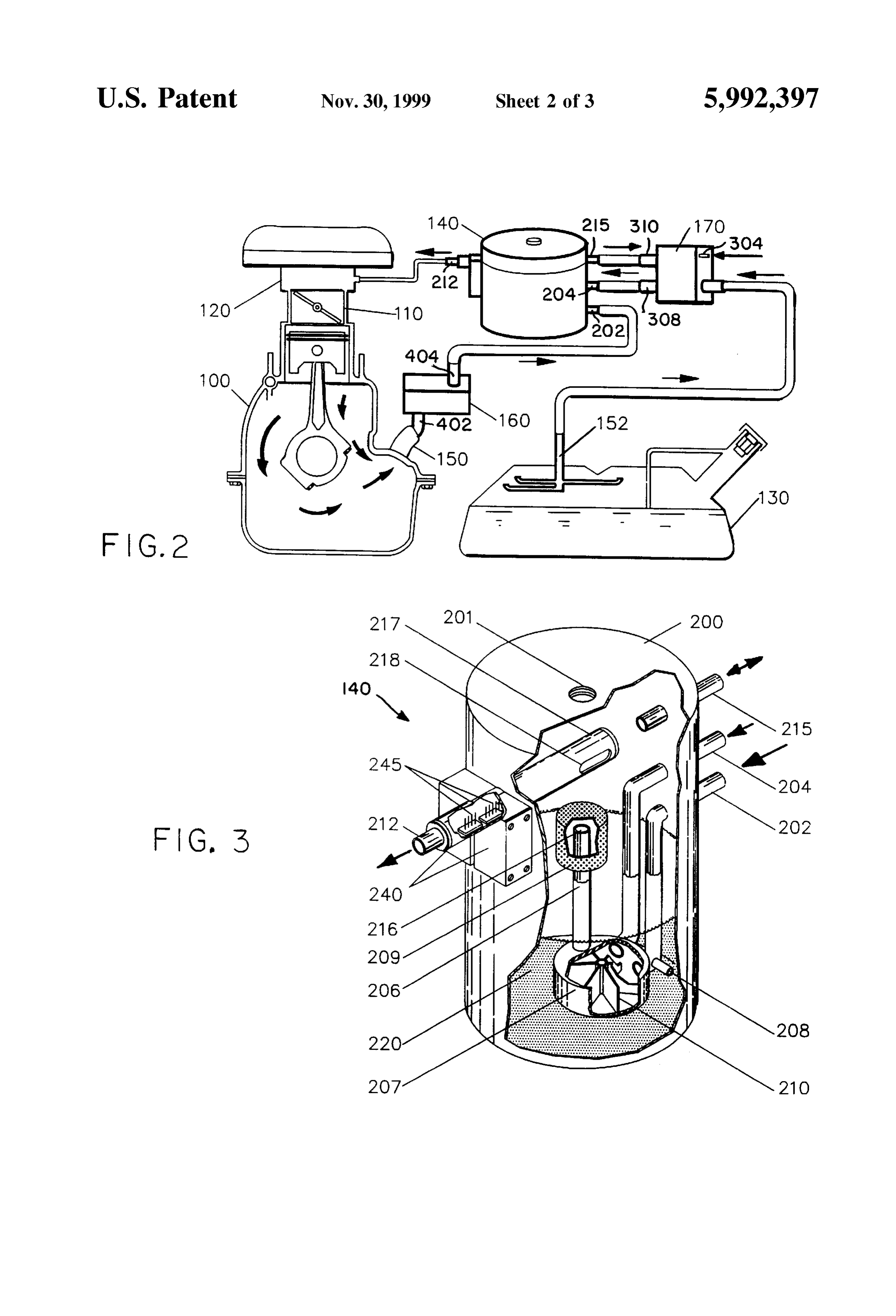
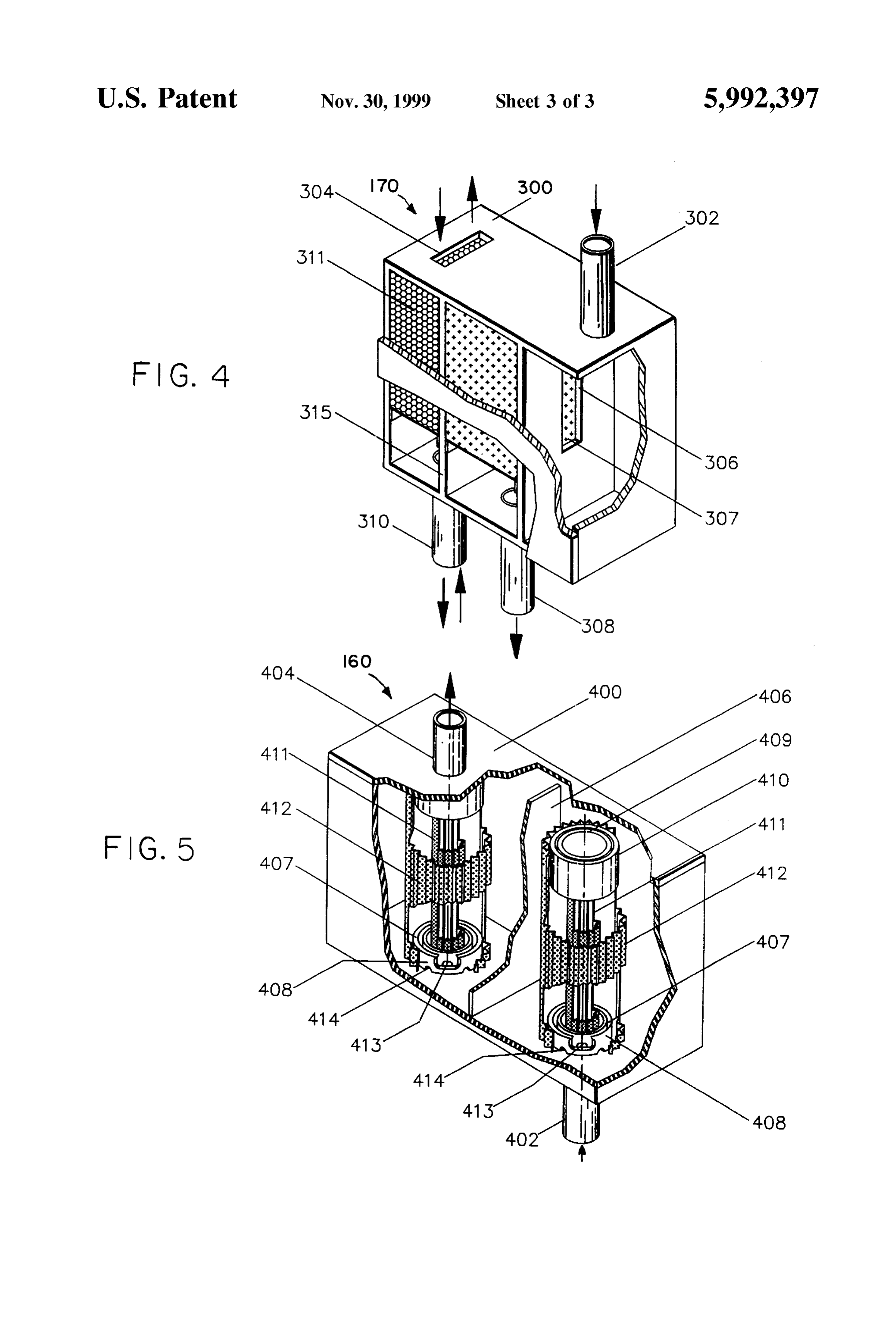
FIG. 1, already described, is an illustration of energy loSS The carbon canister 170 is illustrated in FIGS. 2 and 4 and in a typical internal combustion engine; comprises a housing 300 having an inlet pipe 302 connected FIG. 2 is a Schematic diagram of an engine incorporating to fuel tank outlet 152 and output pipe 308 connected to inlet apparatus according to the invention; 204 of apparatus 140. The pipe 302 connects to an inlet FIG.3 is a part Sectional perspective View of the apparatus channel 306 in housing 300 adjacent an absorbing element of FIG. 2; 307 comprised of pressed charcoal which on the down FIG. 4 is a sectional perspective view of the charcoal 25 stream side is provided with an outlet channel 308 leading to pipe 204 of the apparatus 200. An air inlet 304 is provided canister of the FIG. 2 apparatus, and at the opposed end of the channel 310. Volatile hydrocarbon FIG. 5 is a sectional view of an oil separator filter present gas vapors which vent from the fuel tank through outlet 52 in the FIG. 2 apparatus. are fed through to the inlet 302. These hydrocarbon gas DETAILED DESCRIPTION OF THE Vapors are absorbed and lightly held by the charcoal element PREFERRED EMBODIMENT in cannister 170. When the engine starts, the hydrocarbon gas vapors are drawn through channel 308 and air flows
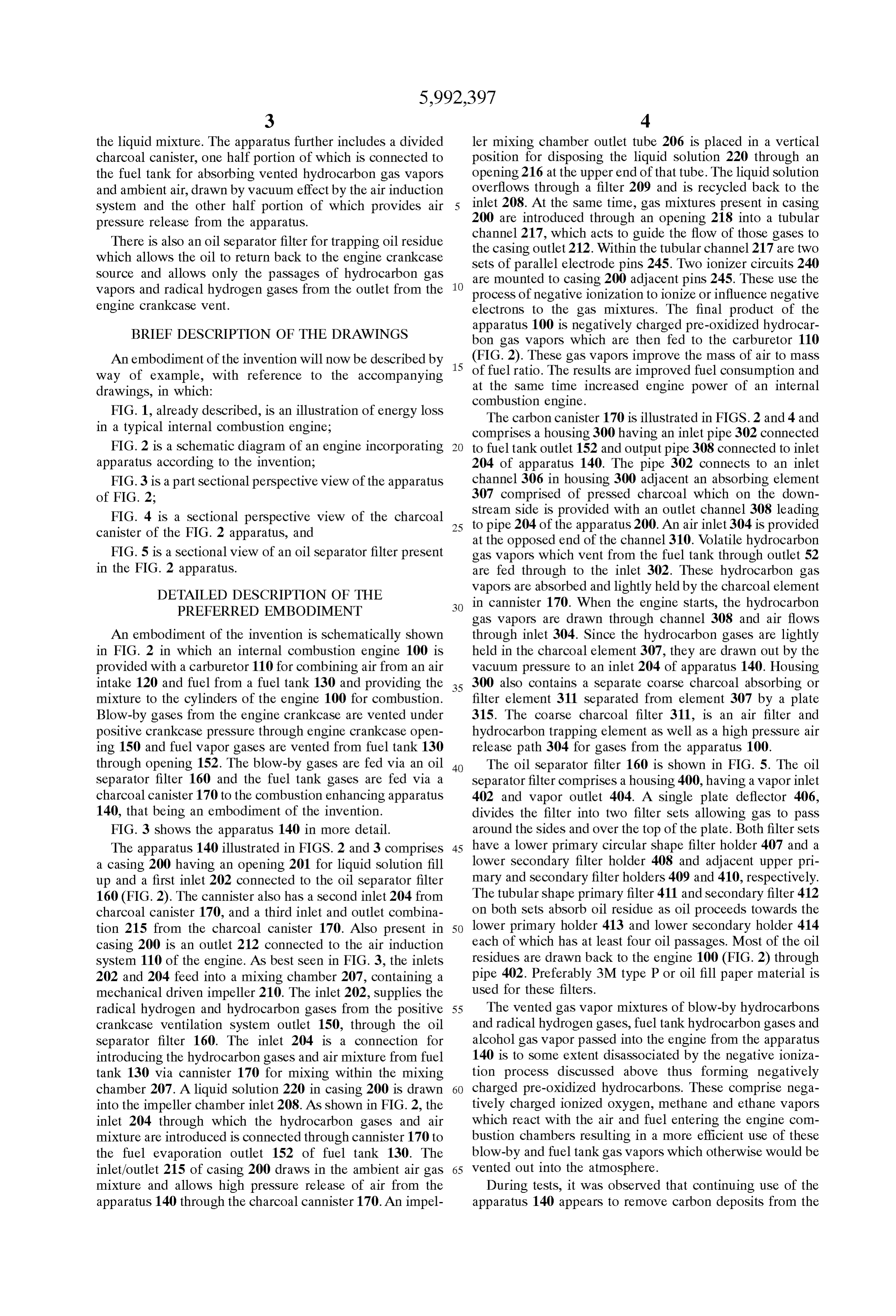
An embodiment of the invention is schematically shown through inlet 304. Since the hydrocarbon gases are lightly in FIG. 2 in which an internal combustion engine 100 is held in the charcoal element 307, they are drawn out by the provided with a carburetor 110 for combining air from an air vacuum pressure to an inlet 204 of apparatus 140. Housing intake 120 and fuel from a fuel tank 130 and providing the 35 300 also contains a Separate coarse charcoal absorbing or mixture to the cylinders of the engine 100 for combustion. filter element 311 separated from element 307 by a plate Blow-by gases from the engine crankcase are vented under 315. The coarse charcoal filter 311, is an air filter and positive crankcase pressure through engine crankcase open hydrocarbon trapping element as well as a high pressure air ing 150 and fuel vapor gases are vented from fuel tank 130 release path 304 for gases from the apparatus 100. through opening 152. The blow-by gases are fed via an oil 40 The oil separator filter 160 is shown in FIG. 5. The oil separator filter 160 and the fuel tank gases are fed via a Separator filter comprises a housing 400, having a vapor inlet charcoal canister 170 to the combustion enhancing apparatus 402 and vapor outlet 404. A single plate deflector 406, 140, that being an embodiment of the invention. divides the filter into two filter Sets allowing gas to pass FIG. 3 shows the apparatus 140 in more detail. around the sides and over the top of the plate. Both filter sets The apparatus 140 illustrated in FIGS. 2 and 3 comprises 45 have a lower primary circular shape filter holder 407 and a a casing 200 having an opening 201 for liquid solution fill lower secondary filter holder 408 and adjacent upper pri up and a first inlet 202 connected to the oil separator filter mary and secondary filter holders 409 and 410, respectively. 160 (FIG. 2). The cannister also has a second inlet 204 from The tubular shape primary filter 411 and secondary filter 412 charcoal canister 170, and a third inlet and outlet combina on both Sets absorb oil residue as oil proceeds towards the tion 215 from the charcoal canister 170. Also present in 50 lower primary holder 413 and lower secondary holder 414 casing 200 is an outlet 212 connected to the air induction each of which has at least four oil passages. Most of the oil system 110 of the engine. As best seen in FIG. 3, the inlets residues are drawn back to the engine 100 (FIG. 2) through 202 and 204 feed into a mixing chamber 207, containing a pipe 402. Preferably 3M type P or oil fill paper material is mechanical driven impeller 210. The inlet 202, supplies the used for these filters.
radical hydrogen and hydrocarbon gases from the positive 55 The vented gas vapor mixtures of blow-by hydrocarbons crankcase ventilation system outlet 150, through the oil and radical hydrogen gases, fuel tank hydrocarbon gases and separator filter 160. The inlet 204 is a connection for alcohol gas Vapor passed into the engine from the apparatus introducing the hydrocarbon gases and air mixture from fuel 140 is to Some extent disasSociated by the negative ioniza tank 130 via cannister 170 for mixing within the mixing tion proceSS discussed above thus forming negatively chamber 207. A liquid solution 220 in casing 200 is drawn 60 charged pre-oxidized hydrocarbons. These comprise nega into the impeller chamber inlet 208. As shown in FIG. 2, the tively charged ionized oxygen, methane and ethane vapors inlet 204 through which the hydrocarbon gases and air which react with the air and fuel entering the engine com mixture are introduced is connected through cannister 170 to bustion chambers resulting in a more efficient use of these the fuel evaporation outlet 152 of fuel tank 130. The blow-by and fuel tank gas vapors which otherwise would be inlet/outlet 215 of casing 200 draws in the ambient air gas 65 vented out into the atmosphere.
mixture and allows high pressure release of air from the During tests, it was observed that continuing use of the apparatus 140 through the charcoal cannister 170. An impel apparatus 140 appears to remove carbon deposits from the
Page 7
S 6 engine thus providing a carbon cleaning effect, due to the pickup having a two liter fuel injected diesel engine and a excess of negatively charged oxygen, whereby accumulated Mitsubishi tour bus having an engine capacity of 3298 cc. carbon deposits are ignited throughout the combustion
System, eventually cleaning the combustion chamber Sur MEASUREMENT PROCEDURE (MITSUBISHI faces. From the positive crankcase ventilation, the oil Sepa 5 1. Smoke LevelCANTER 1992 LORRY PICKUP) rator filter 160, further traps oil residues and allows the flow of radical hydrogen and hydrocarbon gas vapors into the The Smoke levels were measured using a Hartridge apparatus 140, thus preventing oil residues from entering Smoker.
into the apparatus 140. Oil consumption is also reduced 2. Fuel Consumption Measurement
Since the residual oil returns back into the engine. a. At a constant Speed,
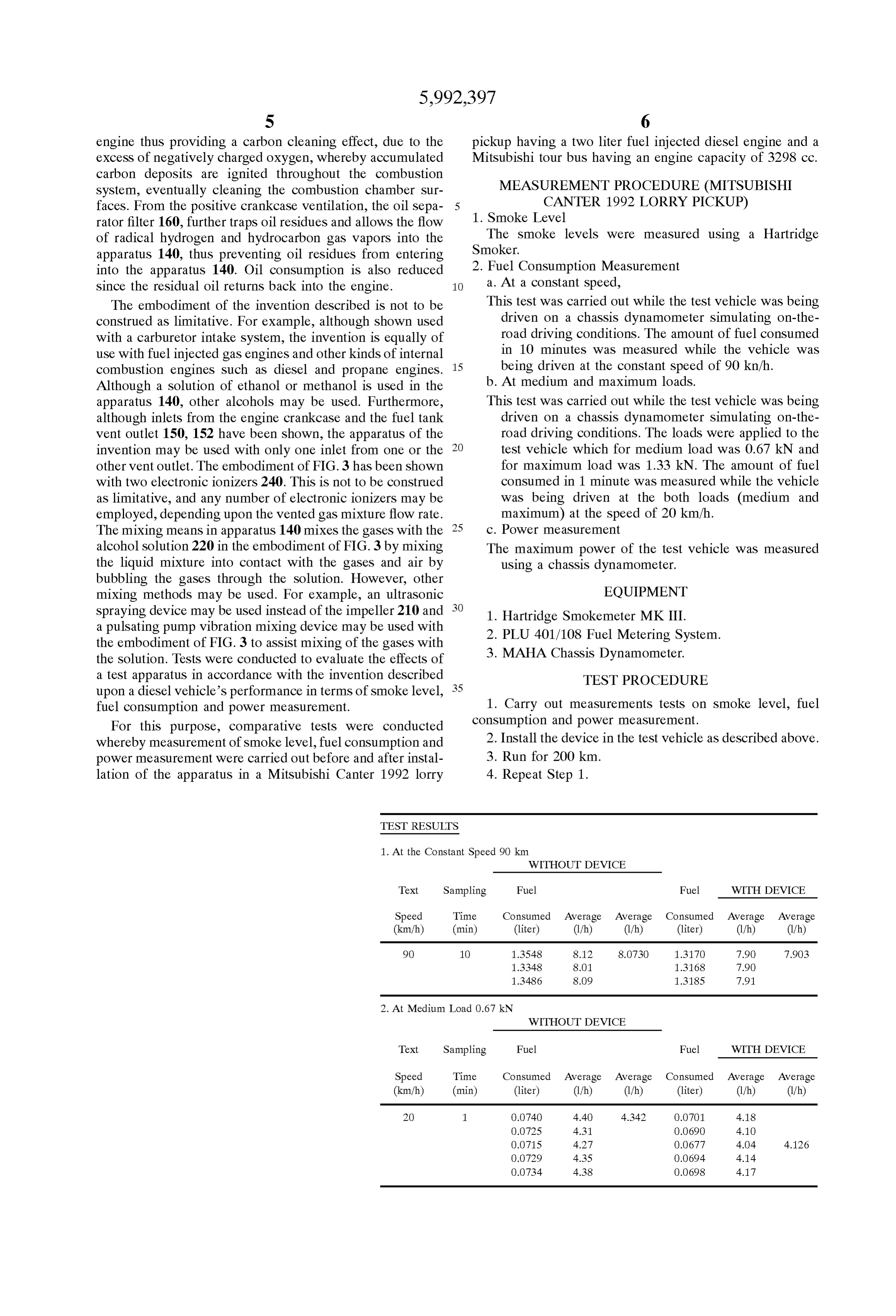
The embodiment of the invention described is not to be This test was carried out while the test vehicle was being construed as limitative. For example, although shown used driven on a chassis dynamometer simulating on-the with a carburetor intake System, the invention is equally of road driving conditions. The amount of fuel consumed use with fuel injected gas engines and other kinds of internal in 10 minutes was measured while the vehicle was combustion engines Such as diesel and propane engines. 15 being driven at the constant speed of 90 kn/h. Although a Solution of ethanol or methanol is used in the b. At medium and maximum loads. apparatus 140, other alcohols may be used. Furthermore, This test was carried out while the test vehicle was being although inlets from the engine crankcase and the fuel tank driven on a chassis dynamometer simulating on-the vent outlet 150, 152 have been shown, the apparatus of the road driving conditions. The loads were applied to the invention may be used with only one inlet from one or the test vehicle which for medium load was 0.67 kN and other vent outlet. The embodiment of FIG.3 has been shown for maximum load was 1.33 kN. The amount of fuel with two electronic ionizers 240. This is not to be construed consumed in 1 minute was measured while the vehicle as limitative, and any number of electronic ionizers may be was being driven at the both loads (medium and employed, depending upon the vented gas mixture flow rate. maximum) at the speed of 20 km/h. The mixing means in apparatuS 140 mixes the gases with the 25 c. Power measurement alcohol solution 220 in the embodiment of FIG.3 by mixing The maximum power of the test vehicle was measured the liquid mixture into contact with the gases and air by using a chassis dynamometer. bubbling the gases through the Solution. However, other mixing methods may be used. For example, an ultrasonic EQUIPMENT Spraying device may be used instead of the impeller 210 and 1. Hartridge Smokemeter MK III. a pulsating pump vibration mixing device may be used with 2. PLU 401/108 Fuel Metering System. the embodiment of FIG.3 to assist mixing of the gases with the Solution. Tests were conducted to evaluate the effects of 3. MAHA Chassis Dynamometer. a test apparatus in accordance with the invention described TEST PROCEDURE upon a diesel vehicle's performance in terms of Smoke level, 35 fuel consumption and power measurement. 1. Carry out measurements tests on Smoke level, fuel For this purpose, comparative tests were conducted consumption and power measurement.
whereby measurement of Smoke level, fuel consumption and 2. Install the device in the test vehicle as described above. power measurement were carried out before and after instal 3. Run for 200 km.
lation of the apparatus in a Mitsubishi Canter 1992 lorry 4. Repeat Step 1.
TEST RESULTS
1. At the Constant Speed 90 km
WITHOUT DEVICE
Text Sampling Fuel Fuel WITH DEVICE
Speed Time Consumed Average Average Consumed Average Average (km/h) (min) (liter) (1/h) (1/h) (liter) (1/h) (1/h) 90 1O 1.3548 8.12 8.0730 1.317O 7.90 7.903
2. At Medium Load 0.67 kN
WITHOUT DEVICE
Text Sampling Fuel Fuel WITH DEVICE
Speed Time Consumed Average Average Consumed Average Average (km/h) (min) (liter) (1/h) (1/h) (liter) (1/h) (1/h) 2O 1. O.O740 4.40 4.342 O.O701 4.18
Page 8
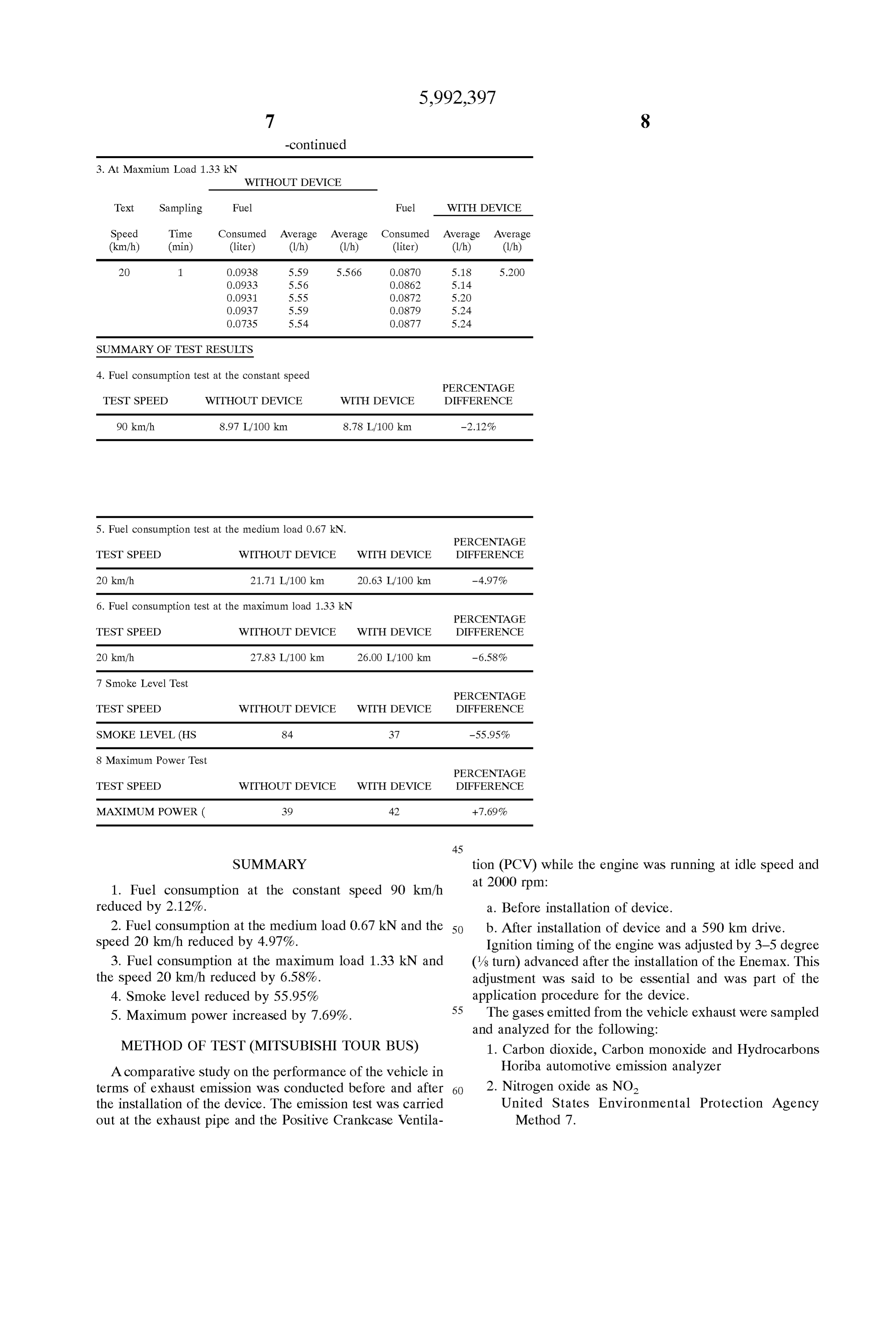
3. At Maxmium Load 1.33 kN
WITHOUT DEVICE
Text Sampling Fuel Fuel WITH DEVICE
Speed Time Consumed Average Average Consumed Average Average (km/h) (min) (liter) (1/h) (1/h) (liter) (1/h) (1/h) 2O 1. O.O938 5.59 5.566 O.O870 5.18 5.2OO
SUMMARY OF TEST RESULTS
4. Fuel consumption test at the constant speed
PERCENTAGE
TEST SPEED WITHOUT DEVICE WITH DEVICE DIFFERENCE
90 km/h 8.97 L/100 km 8.78 L100 km -2.12%
5. Fuel consumption test at the medium load 0.67 kN.
PERCENTAGE
TEST SPEED WITHOUT DEVICE WITH DEVICE DIFFERENCE
20 km/h 21.71 L/100 km 20.63 L/100 km -4.97% 6. Fuel consumption test at the maximum load 1.33 kN
PERCENTAGE
TEST SPEED WITHOUT DEVICE WITH DEVICE DIFFERENCE
20 km/h 27.83 L/100 km 26.00 L/100 km -6.58% 7 Smoke Level Test
PERCENTAGE
TEST SPEED WITHOUT DEVICE WITH DEVICE DIFFERENCE
SMOKE LEVEL (HS 84 37 -55.95% 8 Maximum Power Test
PERCENTAGE
TEST SPEED WITHOUT DEVICE WITH DEVICE DIFFERENCE
MAXIMUM POWER ( 39 42 +7.69%
SUMMARY tion (PCV) while the engine was running at idle speed and 1. Fuel consumption at the constant speed 90 km/h at 2000 rpm.
reduced by 2.12%. a. Before installation of device. 2. Fuel consumption at the medium load 0.67 kN and the 50 b. After installation of device and a 590 km drive. speed 20 km/h reduced by 4.97%. Ignition timing of the engine was adjusted by 3–5 degree 3. Fuel consumption at the maximum load 1.33 kN and (/s turn) advanced after the installation of the Enemax. This the speed 20 km/h reduced by 6.58%. adjustment was said to be essential and was part of the 4. Smoke level reduced by 55.95% application procedure for the device. 55 The gases emitted from the vehicle exhaust were Sampled 5. Maximum power increased by 7.69%.
and analyzed for the following:
METHOD OF TEST (MITSUBISHI TOUR BUS) 1. Carbon dioxide, Carbon monoxide and Hydrocarbons A comparative Study on the performance of the vehicle in Horiba automotive emission analyzer terms of exhaust emission was conducted before and after 60 2. Nitrogen oxide as NO the installation of the device. The emission test was carried United States Environmental Protection Agency out at the exhaust pipe and the Positive Crankcase Ventila Method 7.
Page 9
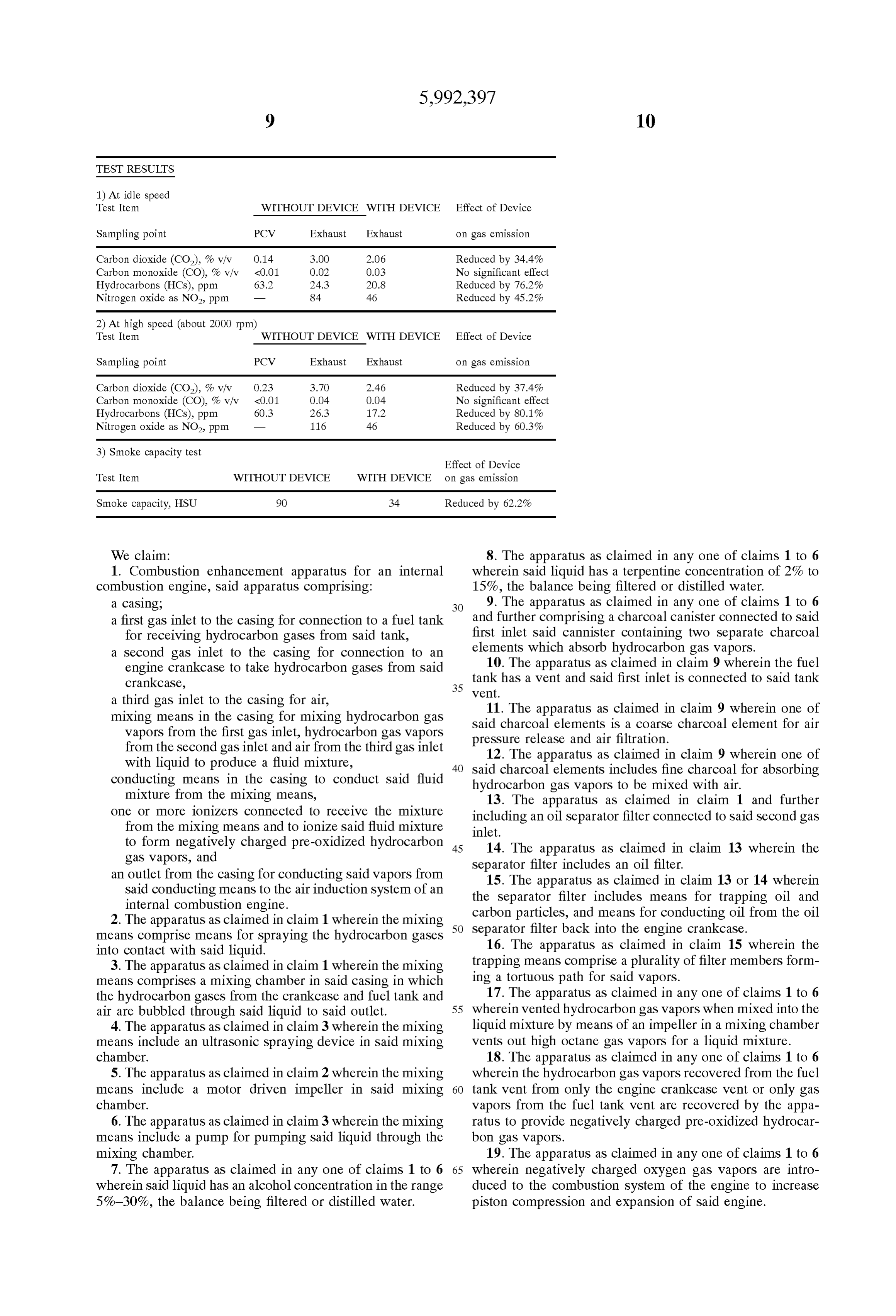
TEST RESULTS
1) At idle speed
Test Item WITHOUT DEVICE WITH DEVICE Effect of Device
Sampling point PCV Exhaust Exhaust on gas emission
Carbon dioxide (CO), 76 viv O.14 3.OO 2.06 Reduced by 34.4%
Carbon monoxide (CO), 76 v/v <0.01 O.O2 O.O3 No significant effect
Hydrocarbons (HCs), ppm 63.2 24.3 20.8 Reduced by 76.2%
Nitrogen oxide as NO2, ppm 84 46 Reduced by 45.2% 2) At high speed (about 2000 rpm)
Test Item WITHOUT DEVICE WITH DEVICE Effect of Device
Sampling point PCV Exhaust Exhaust on gas emission
Carbon dioxide (CO), 76 viv O.23 3.70 2.46 Reduced by 37.4%
Carbon monoxide (CO), 76 v/v <0.01 O.04 O.O4 No significant effect
Hydrocarbons (HCs), ppm 603 26.3 17.2 Reduced by 80.1%
Nitrogen oxide as NO2, ppm 116 46 Reduced by 60.3% 3) Smoke capacity test
Effect of Device
Test Item WITHOUT DEVICE WITH DEVICE on gas emission
Smoke capacity, HSU 90 34 Reduced by 62.2%
We claim: 8. The apparatus as claimed in any one of claims 1 to 6 1. Combustion enhancement apparatus for an internal wherein Said liquid has a terpentine concentration of 2% to combustion engine, Said apparatus comprising: 15%, the balance being filtered or distilled water. a casing: 9. The apparatus as claimed in any one of claims 1 to 6 a first gas inlet to the casing for connection to a fuel tank and further comprising a charcoal canister connected to Said for receiving hydrocarbon gases from Said tank, first inlet Said cannister containing two Separate charcoal a second gas inlet to the casing for connection to an elements which absorb hydrocarbon gas Vapors. engine crankcase to take hydrocarbon gases from Said 10. The apparatus as claimed in claim 9 wherein the fuel crankcase, tank has a vent and Said first inlet is connected to Said tank
Vent.
a third gas inlet to the casing for air, mixing means in the casing for mixing hydrocarbon gas Said11.charcoal The apparatus as claimed in claim 9 wherein one of elements is a coarse charcoal element for air
Vapors from the first gas inlet, hydrocarbon gas vapors preSSure release and air filtration. from the Second gas inlet and air from the third gas inlet 12. The apparatus as claimed in claim 9 wherein one of with liquid to produce a fluid mixture, 40 Said charcoal elements includes fine charcoal for absorbing conducting means in the casing to conduct said fluid hydrocarbon gas vapors to be mixed with air.
mixture from the mixing means, 13. The apparatus as claimed in claim 1 and further one or more ionizers connected to receive the mixture including an oil Separator filter connected to Said Second gas from the mixing means and to ionize Said fluid mixture inlet.
to form negatively charged pre-oxidized hydrocarbon 45 14. The apparatus as claimed in claim 13 wherein the gas Vapors, and an outlet from the casing for conducting Said vapors from Separator 15. The filter includes an oil filter.
apparatus as claimed in claim 13 or 14 wherein
Said conducting means to the air induction System of an the Separator filter includes means for trapping oil and internal combustion engine.
2. The apparatus as claimed in claim 1 wherein the mixing 50 carbon particles, and means for conducting oil from the oil means comprise means for Spraying the hydrocarbon gases Separator filter back into the engine crankcase. into contact with Said liquid. 16. The apparatus as claimed in claim 15 wherein the 3. The apparatus as claimed in claim 1 wherein the mixing trapping means comprise a plurality of filter members form means comprises a mixing chamber in Said casing in which ing a tortuous path for Said vapors.
the hydrocarbon gases from the crankcase and fuel tank and 17. The apparatus as claimed in any one of claims 1 to 6 air are bubbled through said liquid to said outlet. 55 whereinvented hydrocarbon gas vapors when mixed into the 4. The apparatus as claimed in claim3 wherein the mixing liquid mixture by means of an impeller in a mixing chamber means include an ultraSonic spraying device in Said mixing vents out high octane gas vapors for a liquid mixture. chamber. 18. The apparatus as claimed in any one of claims 1 to 6 5. The apparatus as claimed in claim 2 wherein the mixing wherein the hydrocarbon gas vapors recovered from the fuel means include a motor driven impeller in Said mixing 60 tank vent from only the engine crankcase vent or only gas chamber. Vapors from the fuel tank vent are recovered by the appa 6. The apparatus as claimed in claim3 wherein the mixing ratus to provide negatively charged pre-oxidized hydrocar means include a pump for pumping Said liquid through the bon gas vapors.
mixing chamber. 19. The apparatus as claimed in any one of claims 1 to 6 7. The apparatus as claimed in any one of claims 1 to 6 65 wherein negatively charged oxygen gas vapors are intro wherein Said liquid has an alcohol concentration in the range duced to the combustion System of the engine to increase 5%-30%, the balance being filtered or distilled water. piston compression and expansion of Said engine.
Page 10
20. The apparatus as claimed in any one of claims 1 to 6 passing Said dissociated molecular chains of hydrocarbon wherein two ionizer circuits are connected in parallel, each gas Vapors through one or more ionizers to form having an output power of 1000 to 30,000 negative volts. negatively charged pre-oxidized hydrocarbon gas 21. The apparatus as claimed in any one of claims 1 to 6 Vapors, and wherein negatively charged pre-oxidized hydrocarbon gas introducing the negatively charged pre-Oxidized hydro Vapors are added into the combustion chambers of Said carbon gas vapors into the air induction System of the engine for improving the fuel consumption, thermal effi engine.
ciency and reduction of carbon deposits of Said engine.
22. The apparatus as claimed in any one of claims 1 to 6 27. The method according to claim 26 wherein the vented wherein Said hydrocarbon gas Vapors are recovered to form hydrocarbon gas vapors are mixed into the liquid mixture by ethane and methane hydrocarbon gases for mixing with means of an impeller in a mixing chamber which vents out negatively charged oxygen gas vapors for further combus high octane gas vapors from the liquid mixture. tion. 28. The method according to claim 26 wherein the hydro 23. The apparatus as claimed in any one of claims 1 to 6 carbon gas vapors are recovered from the fuel tank and/or wherein Said negatively charged pre-oxidized hydrocarbon 15 the engine crankcase to provide the negatively charged gas gas vapors are combined with air flowing through the air Vapors.
induction System of Said engine to increase the oxygen ratio 29. The method according to claim 26 wherein negatively of Said engine. charged gas vapors are introduced to the combustion cham 24. The apparatus as claimed in any one of claims 1 to 6 bers of the engine to increase piston compression and wherein Said negatively charged pre-oxidized hydrocarbon expansion of the engine.
gas vapors are combined with ambient air to improve the air 30. The method according to claim 26 wherein the nega to fuel ratio for Said engine. tively charged gas vapors are added into the combustion 25. The apparatus as claimed in any one of claims 1 to 6 chambers of the engine for improving fuel consumption, wherein hydrocarbon gas Vapors from Said fuel tank and thermal efficiency and reduction of carbon deposits of the crankcase are fed via Said apparatus to the air induction 25 engine.
System of Said engine. 31. The method according to claim 26 wherein the vented 26. A method to improve the ratio of mass of air to mass hydrocarbon gas vapors are recovered to form ethane and of fuel comprising the Steps of methane hydrocarbon gases for mixing with negatively taking vented hydrocarbon gas Vapors from a fuel tank charged oxygen gas Vapors for further combustion. and taking vented hydrocarbon gas vapors from an 32. The method according to claim 26, wherein the engine crankcase, negatively charged gas vapors are combined with the air taking ambient air from the atmosphere, flowing through the air induction system of the engine to mixing the Vented hydrocarbon gas Vapors and ambient increase the oxygen ratio of the engine.
air with a liquid mixture of water and alcohol, 35 33. The method according to claim 26 wherein the nega causing dissociation of molecular chains of the hydrocar tively charged gas vapors are mixed with ambient air to bon gas Vapors, improve air to fuel ratio for the engine. expelling the dissociated molecular chains of the hydro carbon gas Vapors from the liquid mixture, k k k k k
Provenance
- Collection
- Cited prior art
- Original PDF
- patentimages.storage.googleapis.com →
- Filed
- 1997-06-30
- Pages
- 10
- Method
- pdftotext (the PDF's own text layer) + pdftoppm 300dpi page scans
- Source
- Google Patents bibliographic record
- Granted
- 1999-11-30
- Inventors
- Watase Hideaki; Dalupan Romulo Vallejos; Tan Slew Lay
- Transcribed from
- patentimages.storage.googleapis.com →