patent · US4402188
Nested thermal reservoirs with heat pumping therebetween
6 September 1983
Page 1 — bibliographic record
United States Patent (19) 11 4,402,188 Skala 45 Sep. 6, 1983 (54). NESTED THERMAL RESERVOIRS WITH (56) References Cited HEAT PUMPING THEREBETWEEN U.S. PATENT DOCUMENTS 2,713,252 7/1955 Jackson et al. ....................... 165/18 76 Inventor: Stephen F. Skala, 3839 S. Wenonah 3,780,356 12/1973 Laing ................................ 165/10 X Ave., Berwyn, Ill. 60402 4,063,546 12/1977 Schmid et al. .................... 165/10 X 4, 170,261 10/1979 Laing et al. ....................... 165/10 X (21) Appl No.: 307 757 4,219,076 8/1980 Robinson, Jr. ............ 165/104,11 X
FOREIGN PATENT DOCUMENTS
22 Filed: Oct. 1, 1981 2000859 1/1979 United Kingdom ............... 62/238.6 Primary Examiner-Albert W. Davis, Jr.
Related U.S. Application Data Attorney, Agent, or Firm-Stephen F. Skala 63 Continuation-in-part of Ser. No. 56,739, Jul. 11, 1979, (57) ABSTRACT abandoned. An assembly of nested thermal reservoirs has an inner reservoir at an extreme temperature surrounded by one
I51) Int. Cl. .............................................. F25B 27/02 or more reservoirs at moderate temperatures. Over 52 U.S. Cl. ....................................... 62/56; 62/238.6; time, heat flow would equilibrate reservoir tempera 62/430; 62/238.7; 165/10; 165/104.11; 165/18; tures thereby loosing available thermal energy. At least 165/48 R a portion of the heat lost by the inner to an outer reser 58) Field of Search ...................... 165/18, 48, 104.11, voir is restored by a heat pump operating therebetween. 165/10; 62/3, 56,324. 1, 238.7, 238.6, 430, 437;
Page 2
Drawing sheet — no readable text.
Page 3
Drawing sheet — no readable text.
Page 4
and users, it would be desirable to provide fluid circuits
NESTED THERMAL RESERVOIRS WITH HEAT to enable a single heat pump to charge a plurality of PUMPING THEREBETWEEN reservoirs. 't.'
BACKGROUND OBJECTS AND SUMMARY
The present application is a continuation-in-part of It is an object of the invention to provide an im Ser. No. 56,739 filed July 11, 1979 and now abandoned. proved energy efficient thermal storage system and This invention relates to transfer of heat by a heat charging means therefor wherein heat flowing to a pump between thermal reservoirs in a nested configura 10 reservoir at a moderate temperature in a nested assem tion. bly of reservoirs is returned to a reservoir at a more A particular application for the thermal reservoirs extreme temperature thereby maintaining a balance of and heat pump of the invention is a system of domestic predetermined levels of charge.
appliances disclosed in my U.S. Pat. No. 4,173,993 It is another object to provide heat exchange between wherein a liquid phase thermal exchange fluid is forced 15 a plurality of reservoirs by a single heat pump. to circulate in paths which include cooking appliances These and other objects and advantages which will and thermal reservoirs. The appliances are character become apparent are attained by the invention wherein ized as intermittent users having a range of operating a heat pump transfers heat among thermal reservoirs temperatures. Temperature inputs to the appliances which are in a nested configuration. Heat flows continu may range from an extreme of 300° C. for roasting ously to discharge an inner reservoir at an extreme through a more moderate 150° C. for pressure cooking 20 temperature while the surrounding reservoir may be to a yet more moderate 65 C. for maintaining food at a come charged in excess of potential demand. Of various serving temperature. Temperature inputs to cooling thermal sources, the moderate temperature reservoir appliances may range from an extreme of -30° C. for normally has the smallest temperature difference with freezing to a moderate 0° C. for refrigeration. the extreme temperature reservoir and accordingly Among various thermal sources, heat pumps can 25 provides the highest value of Cp.
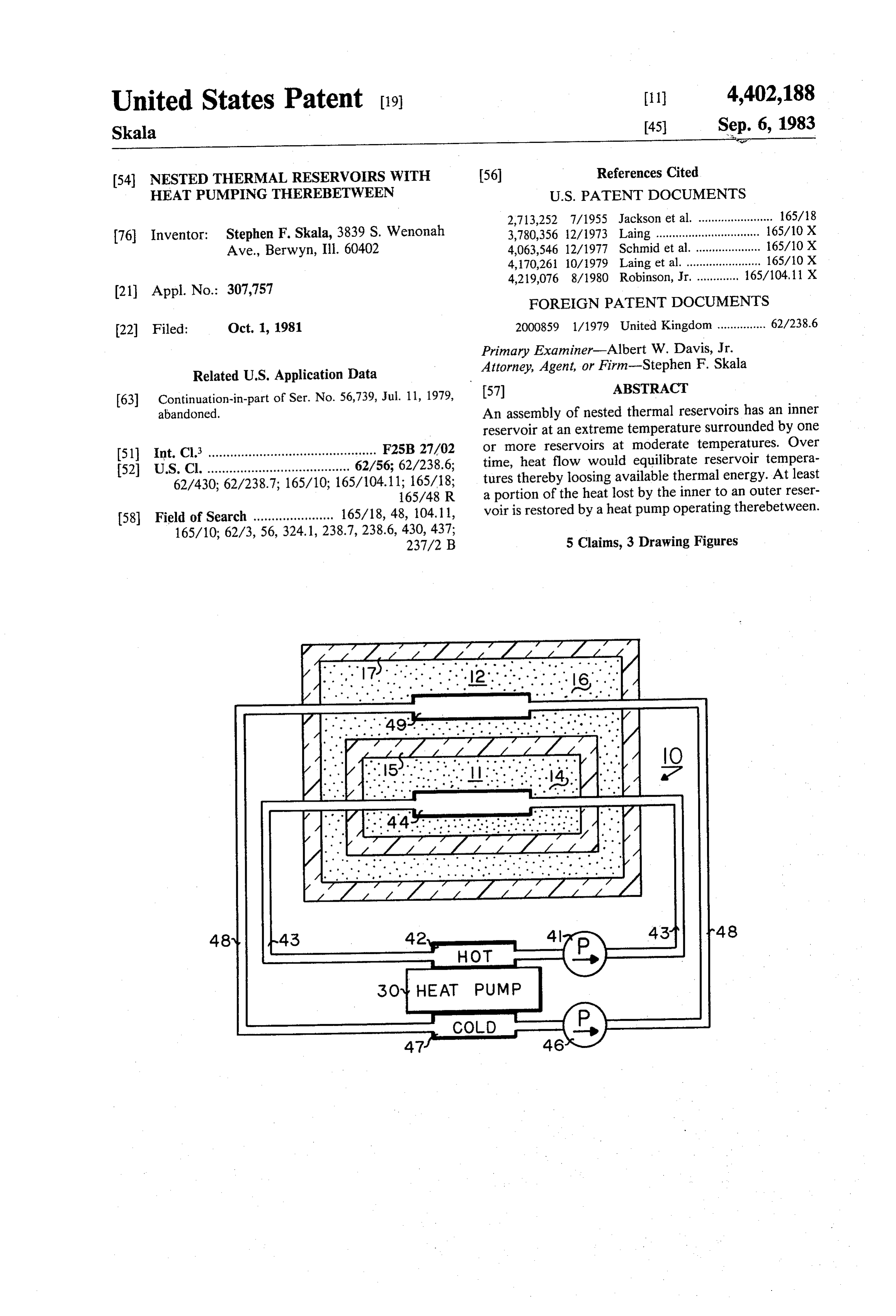
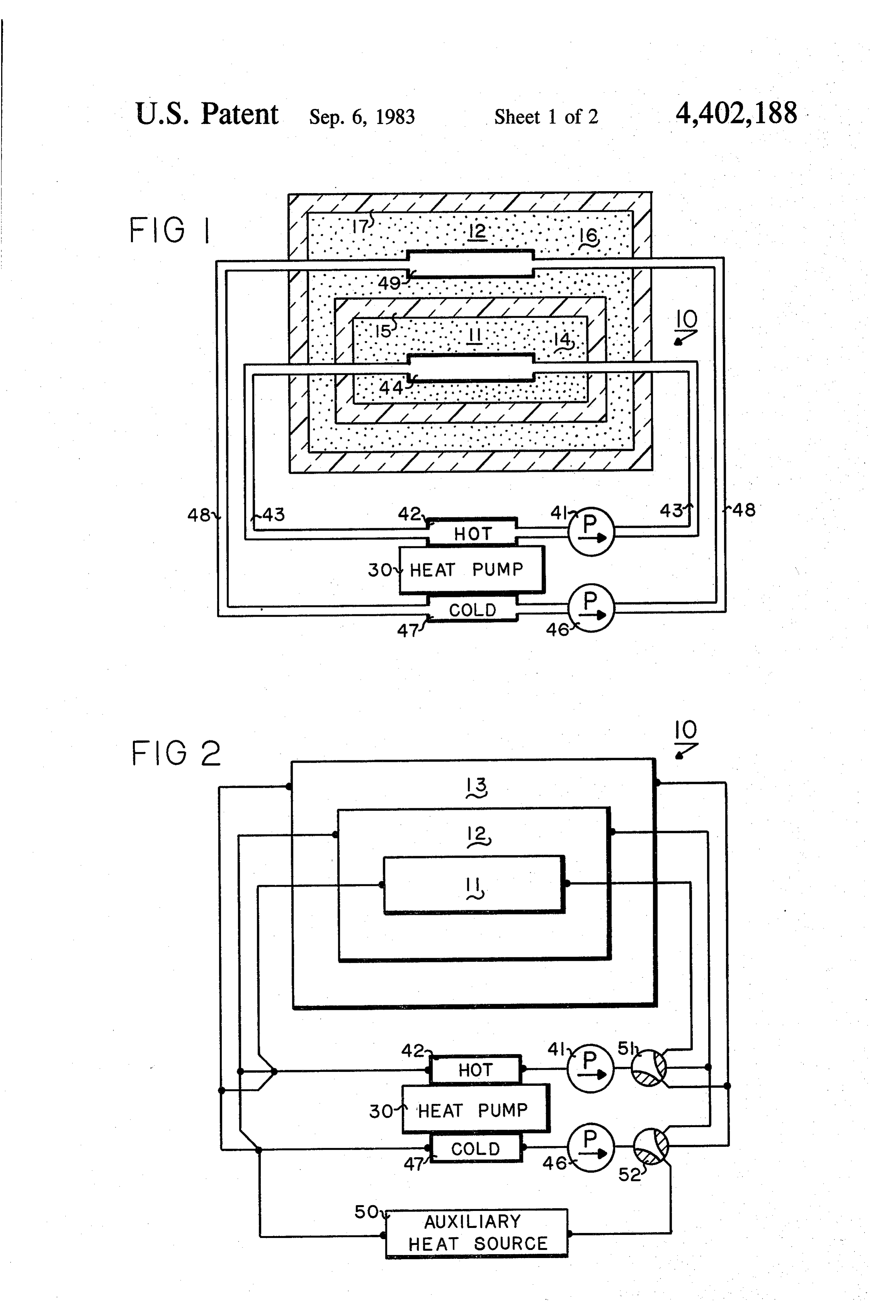
approach an optimal energy efficiency over a wide range of hot and cold temperatures. The theoretical DESCRIPTION OF THE DRAWINGS coefficient of performance, Cp of a heat pump operat FIG. 1 is a diagrammatic drawing partly in side sec ing in a reverse Carnot cycle is expressed in terms of tion showing an elementary embodiment of the inven
absolute temperature of a heat source, Tc, and absolute tion wherein heat is transferred by a heat pump to re temperature of a heat sink, Th, by C=Th/(Th-T). As an example, a heat pump operating in ambient air to store a balance of charge between reservoirs in a nested configuration.
generate heat at a temperature of 150 C. has a theoreti FIG. 2 is a schematic drawing of the invention having cal C of 3.25. Practical heat pumps have a coefficient of a single heat pump to transfer heat between selected performance ranging from 40% to 75% of theoretical 35 pairs of thermal so that in the example of 150° C., the heat would be from an auxiliaryreservoirs and to charge the reservoirs heat source.
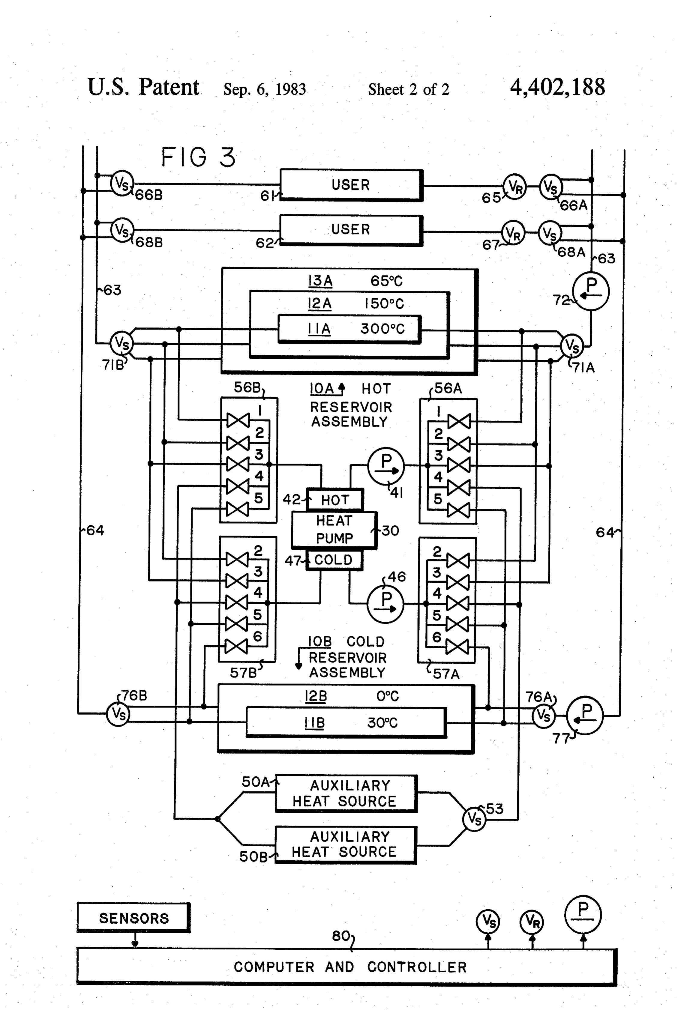
transferred at a practical Cp of 1.3 to 2.4 FIG. 3 is a schematic drawing showing the nested High peak thermal capacity is attained with heat reservoirs and heat pump according to the invention pumps of moderate powr by combining them with ther incorporated into a system of domestic appliances, mal reservoirs for charging over extended periods. In 40
FIG. 1 comprises an assembly of nested thermal res order to approach the high energy efficiency indicated by the Cp for practical heat pumps, a thermal system ervoirs 10, a heat pump 10, and fluid circuits through includes a plurality of thermal reservoirs spanning a heat which a thermal exchange fluid is forced to circulate for range of temperatures. A user selects for heat exchange exchange between the heat pump and the reser the reservoir having the most moderate temperature 45 voirs. An inner reservoir 11 comprises a heat storing mate which satisfies the user's current temperature require ment. Although the user could exchange the same quan rial 14 which is enclosed by a thermal insulator 15. A tity of heat with a reservoir at a more extreme tempera surrounding reservoir 12 comprises a heat storing mate ture, such heat would have been developed at a lower rial 16 which is enclosed by a thermal insulation 17. energy efficiency. 50 Heat storage as latent heat of phase transition is pre Although highly effective thermal insulating systems ferred for large thermal capacity at a predetermined such as evacuated multilayers can reduce heat loss to temperature. Latent heat storing material 14 of the inner low levels, the more economical conventional insula reservoir has its phase transition at an extreme tempera tions loose substantial quantities of heat to surrounding ture and latent heat storing material 16 of the surround media. A nested configuration wherein a reservoir at an 55 ing reservoir has its phase transition at a moderate tem extreme temperature is surrounded by one or more perature.
reservoirs at progressively more moderate temperatures A heat pump 30 may be any of the known thermo reduces the heat loss by a reduced temperature differen electric or mechanical devices which transfer heat from tial across the insulation. The heat which does flow at a source to a higher temperature sink. When operating, the reduced rate is substantially retained by surrounding 60 these devices develop a hot surface and a cold surface. reservoirs and can be used, but it is desirable to balance Conventionally, a condensible gaseous working fluid is the charge of the reservoirs at a high energy efficiency compressed to form a liquid phase as it releases heat to for anticipated user demand. the hot surface and the liquid working fluid absorbs heat Thermal storage systems having more than two reser from the cold surface as it evaporates to its gaseous voirs may include several heat pumps, each of which 65 phase. An alternative and preferred heat pump is based charges one of the reservoirs. In systems such as the on a noncondensible gaseous working fluid in a reverse cited domestic appliance system wherein a common Carnot cycle to provide efficient operation over a wide heat exchange fluid exchanges heat between reservoirs range of temperatures. Such cycles are embodied in
Page 5
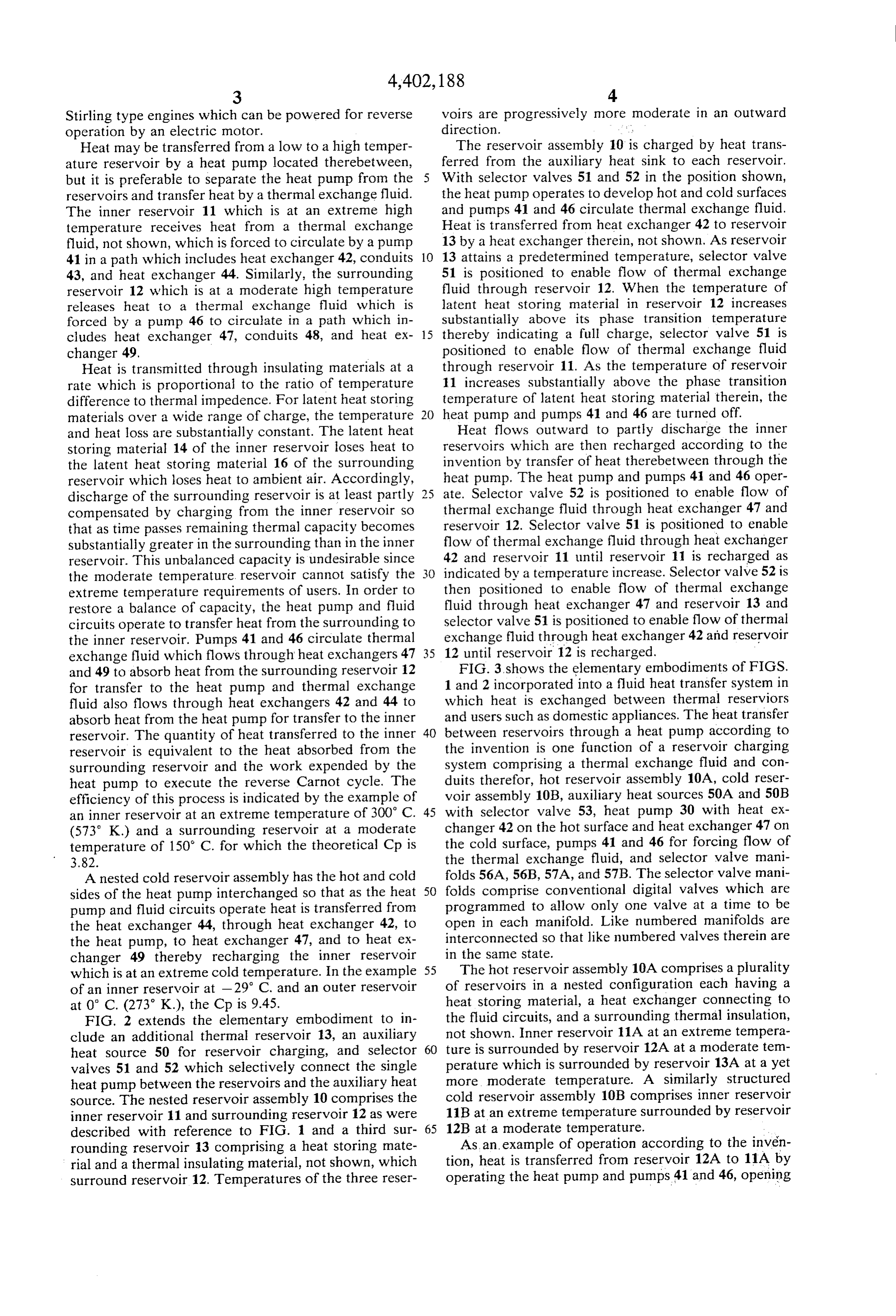
Stirling type engines which can be powered for reverse voirs are progressively more moderate in an outward operation by an electric motor. direction. :, Heat may be transferred from a low to a high temper The reservoir assembly 10 is charged by heat trans ature reservoir by a heat pump located therebetween, ferred from the auxiliary heat sink to each reservoir. but it is preferable to separate the heat pump from the 5 With selector valves 51 and 52 in the position shown, reservoirs and transfer heat by a thermal exchange fluid. the heat pump operates to develop hot and cold surfaces The inner reservoir 11 which is at an extreme high and pumps 41 and 46 circulate thermal exchange fluid. temperature receives heat from a thermal exchange Heat is transferred from heat exchanger 42 to reservoir fluid, not shown, which is forced to circulate by a pump 13 by a heat exchanger therein, not shown. As reservoir 41 in a path which includes heat exchanger 42, conduits 10 13 attains a predetermined temperature, selector valve 43, and heat exchanger 44. Similarly, the surrounding 51 is positioned to enable flow of thermal exchange reservoir 12 which is at a moderate high temperature fluid through reservoir 12. When the temperature of releases heat to a thermal exchange fluid which is latent heat storing material in reservoir 12 increases forced by a pump 46 to circulate in a path which in substantially above its phase transition temperature cludes heat exchanger 47, conduits 48, and heat ex- 15 thereby indicating a full charge, selector valve 51 is changer 49. positioned to enable flow of thermal exchange fluid Heat is transmitted through insulating materials at a through reservoir 11. As the temperature of reservoir rate which is proportional to the ratio of temperature 11 increases substantially above the phase transition difference to thermal impedence. For latent heat storing temperature of latent heat storing material therein, the materials over a wide range of charge, the temperature 20 heat pump and pumps 41 and 46 are turned off. and heat loss are substantially constant. The latent heat Heat flows outward to partly discharge the inner storing material 14 of the inner reservoir loses heat to reservoirs which are then recharged according to the the latent heat storing material 16 of the surrounding invention by transfer of heat therebetween through the reservoir which loses heat to ambient air. Accordingly, heat pump. The heat pump and pumps 41 and 46 oper discharge of the surrounding reservoir is at least partly 25 ate. Selector valve 52 is positioned to enable flow of compensated by charging from the inner reservoir So thermal exchange fluid through heat exchanger 47 and that as time passes remaining thermal capacity becomes reservoir 12. Selector valve 51 is positioned to enable substantially greater in the surrounding than in the inner flow of thermal exchange fluid through heat exchanger reservoir. This unbalanced capacity is undesirable since 42 and reservoir 11 until reservoir 11 is recharged as the moderate temperature reservoir cannot satisfy the 30 indicated by a temperature increase. Selector valve 52 is extreme temperature requirements of users. In order to then positioned to enable flow of thermal exchange restore a balance of capacity, the heat pump and fluid fluid through heat exchanger 47 and reservoir 13 and circuits operate to transfer heat from the surrounding to selector valve 51 is positioned to enable flow of thermal the inner reservoir. Pumps 41 and 46 circulate thermal exchange fluid through heat exchanger 42 and reservoir exchange fluid which flows through heat exchangers 47 35 12 until reservoir 12 is recharged. and 49 to absorb heat from the surrounding reservoir 12 FIG. 3 shows the elementary embodiments of FIGS. for transfer to the heat pump and thermal exchange 1 and 2 incorporated into a fluid heat transfer system in fluid also flows through heat exchangers 42 and 44 to which heat is exchanged between thermal reserviors absorb heat from the heat pump for transfer to the inner and users such as domestic appliances. The heat transfer reservoir. The quantity of heat transferred to the inner 40 between reservoirs through a heat pump according to reservoir is equivalent to the heat absorbed from the the invention is one function of a reservoir charging surrounding reservoir and the work expended by the system comprising a thermal exchange fluid and con heat pump to execute the reverse Carnot cycle. The duits therefor, hot reservoir assembly 10A, cold reser efficiency of this process is indicated by the example of voir assembly 10B, auxiliary heat sources 50A and 50B an inner reservoir at an extreme temperature of 300° C. 45 with selector valve 53, heat pump 30 with heat ex (573 K.) and a surrounding reservoir at a moderate changer 42 on the hot surface and heat exchanger 47 on temperature of 150° C. for which the theoretical Cp is the cold surface, pumps 41 and 46 for forcing flow of 3.82. the thermal exchange fluid, and selector valve mani A nested cold reservoir assembly has the hot and cold folds 56A, 56B, 57A, and 57B. The selector valve mani sides of the heat pump interchanged so that as the heat 50 folds comprise conventional digital valves which are pump and fluid circuits operate heat is transferred from programmed to allow only one valve at a time to be the heat exchanger 44, through heat exchanger 42, to open in each manifold. Like numbered manifolds are the heat pump, to heat exchanger 47, and to heat ex interconnected so that like numbered valves therein are changer 49 thereby recharging the inner reservoir in the same state.
which is at an extreme cold temperature. In the example 55 The hot reservoir assembly 10A comprises a plurality of an inner reservoir at -29 C. and an outer reservoir of reservoirs in a nested configuration each having a at 0° C. (273 K.), the Cp is 9.45. heat storing material, a heat exchanger connecting to FIG. 2 extends the elementary embodiment to in the fluid circuits, and a surrounding thermal insulation, clude an additional thermal reservoir 13, an auxiliary not shown. Inner reservoir 11A at an extreme tempera heat source 50 for reservoir charging, and selector 60 ture is surrounded by reservoir 12A at a moderate tem valves 51 and 52 which selectively connect the single perature which is surrounded by reservoir 13A at a yet heat pump between the reservoirs and the auxiliary heat more moderate temperature. A similarly structured source. The nested reservoir assembly 10 comprises the cold reservoir assembly 10B comprises inner reservoir inner reservoir 11 and surrounding reservoir 12 as were 11B at an extreme temperature surrounded by reservoir described with reference to FIG. 1 and a third sur- 65 12B at a moderate temperature.
rounding reservoir 13 comprising a heat storing mate As an example of operation according to the inven rial and a thermal insulating material, not shown, which tion, heat is transferred from reservoir 12A to 11A by surround reservoir 12. Temperatures of the three reser operating the heat pump and pumps 41 and 46, opening
Page 6
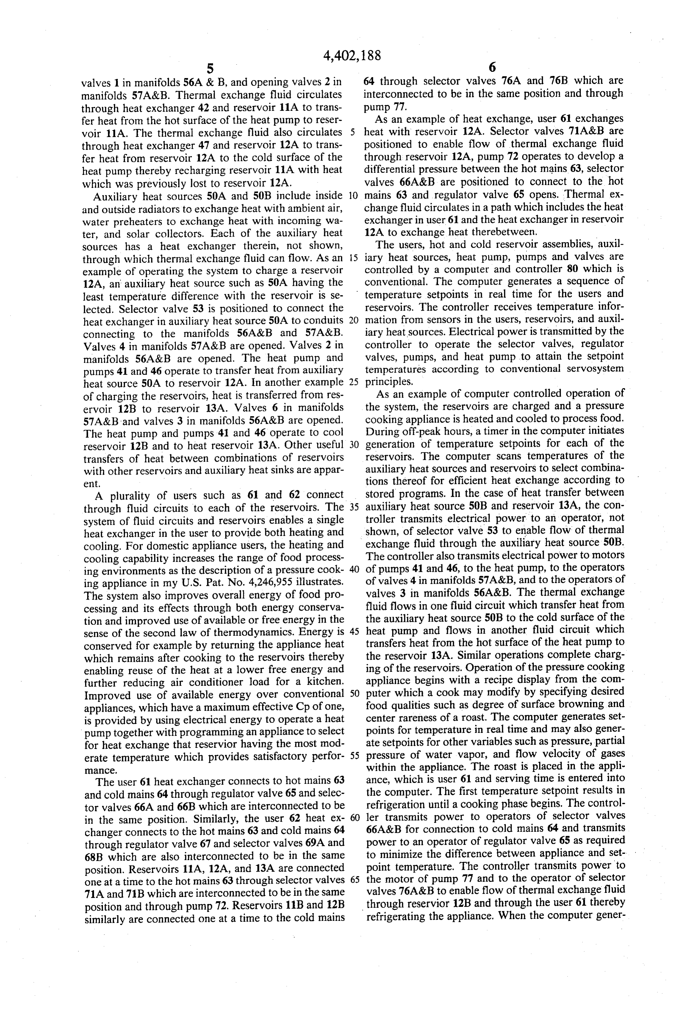
valves 1 in manifolds 56A & B, and opening valves 2 in 64 through selector valves 76A and 76B which are manifolds 57A&B. Thermal exchange fluid circulates interconnected to be in the same position and through through heat exchanger 42 and reservoir 11A to trans pump 77. - fer heat from the hot surface of the heat pump to reser As an example of heat exchange, user 61 exchanges voir 11A. The thermal exchange fluid also circulates heat with reservoir 12A. Selector valves 71A&B are through heat exchanger 47 and reservoir 12A to trans positioned to enable flow of thermal exchange fluid fer heat from reservoir 12A to the cold surface of the through reservoir 12A, pump 72 operates to develop a heat pump thereby recharging reservoir 11A with heat differential pressure between the hot mains 63, selector which was previously lost to reservoir 12A. valves 66A&B are positioned to connect to the hot Auxiliary heat sources 50A and 50B include inside 10 mains 63 and regulator valve 65 opens. Thermal ex and outside radiators to exchange heat with ambient air, change fluid circulates in a path which includes the heat water preheaters to exchange heat with incoming wa exchanger in user 61 and the heat exchanger in reservoir ter, and solar collectors. Each of the auxiliary heat 12A to exchange heat therebetween.
sources has a heat exchanger therein, not shown, The users, hot and cold reservoir assemblies, auxil through which thermal exchange fluid can flow. As an 5 iary heat sources, heat pump, pumps and valves are example of operating the system to charge a reservoir controlled by a computer and controller 80 which is 12A, an auxiliary heat source such as 50A having the conventional. The computer generates a sequence of least temperature difference with the reservoir is se temperature setpoints in real time for the users and lected. Selector valve 53 is positioned to connect the reservoirs. The controller receives temperature infor heat exchanger in auxiliary heat source 50A to conduits 20 mation from sensors in the users, reservoirs, and auxil connecting to the manifolds 56A&B and 57A&B. iary heat sources. Electrical power is transmitted by the Valves 4 in manifolds 57A&B are opened. Valves 2 in controller to operate the selector valves, regulator manifolds 56A&B are opened. The heat pump and Valves, pumps, and heat pump to attain the setpoint pumps 41 and 46 operate to transfer heat from auxiliary temperatures according to conventional servosystem heat source 50A to reservoir 12A. In another example 25 principles.
of charging the reservoirs, heat is transferred from res As an example of computer controlled operation of ervoir 12B to reservoir 13A. Valves 6 in manifolds the system, the reservoirs are charged and a pressure 57A&B and valves 3 in manifolds 56A&B are opened. cooking appliance is heated and cooled to process food. The heat pump and pumps 41 and 46 operate to cool During off-peak hours, a timer in the computer initiates reservoir 12B and to heat reservoir 13A. Other useful 30 generation of temperature setpoints for each of the transfers of heat between combinations of reservoirs reservoirs. The computer scans temperatures of the with other reservoirs and auxiliary heat sinks are appar auxiliary heat sources and reservoirs to select combina ent. tions thereof for efficient heat exchange according to A plurality of users such as 61 and 62 connect stored programs. In the case of heat transfer between through fluid circuits to each of the reservoirs. The 35 auxiliary heat source 50B and reservoir 13A, the con system of fluid circuits and reservoirs enables a single troller transmits electrical power to an operator, not heat exchanger in the user to provide both heating and shown, of selector valve 53 to enable flow of thermal cooling. For domestic appliance users, the heating and exchange fluid through the auxiliary heat source 50B. cooling capability increases the range of food process The controller also transmits electrical power to motors ing environments as the description of a pressure cook 40 of pumps 41 and 46, to the heat pump, to the operators ing appliance in my U.S. Pat. No. 4,246,955 illustrates. of valves 4 in manifolds 57A&B, and to the operators of The system also improves overall energy of food pro valves 3 in manifolds 56A&B. The thermal exchange cessing and its effects through both energy conserva fluid flows in one fluid circuit which transfer heat from tion and improved use of available or free energy in the the auxiliary heat source 50B to the cold surface of the sense of the second law of thermodynamics. Energy is 45 heat pump and flows in another fluid circuit which conserved for example by returning the appliance heat transfers heat from the hot surface of the heat pump to which remains after cooking to the reservoirs thereby the reservoir 13A. Similar operations complete charg enabling reuse of the heat at a lower free energy and ing of the reservoirs. Operation of the pressure cooking further reducing air conditioner load for a kitchen. appliance begins with a recipe display from the com Improved use of available energy over conventional 50 puter which a cook may modify by specifying desired appliances, which have a maximum effective Cp of one, food qualities such as degree of surface browning and is provided by using electrical energy to operate a heat center rareness of a roast. The computer generates set pump together with programming an appliance to select points for temperature in real time and may also gener for heat exchange that reservior having the most mod ate setpoints for other variables such as pressure, partial erate temperature which provides satisfactory perfor 55 pressure of water vapor, and flow velocity of gases aCC. within the appliance. The roast is placed in the appli The user 61 heat exchanger connects to hot mains 63 ance, which is user 61 and serving time is entered into and cold mains 64 through regulator valve 65 and selec the computer. The first temperature setpoint results in tor valves 66A and 66B which are interconnected to be refrigeration until a cooking phase begins. The control in the same position. Similarly, the user 62 heat ex 60 ler transmits power to operators of selector valves changer connects to the hot mains 63 and cold mains 64 66A&B for connection to cold mains 64 and transmits through regulator valve 67 and selector valves 69A and power to an operator of regulator valve 65 as required 68B which are also interconnected to be in the same to minimize the difference between appliance and set position. Reservoirs 11A, 12A, and 13A are connected point temperature. The controller transmits power to one at a time to the hot mains 63 through selector valves 65 the motor of pump 77 and to the operator of selector 71A and 71B which are interconnected to be in the same valves 76A&B to enable flow of thermal exchange fluid position and through pump 72. Reservoirs 11B and 12B through reservior 12B and through the user 61 thereby similarly are connected one at a time to the cold mains refrigerating the appliance. When the computer gener
Page 7
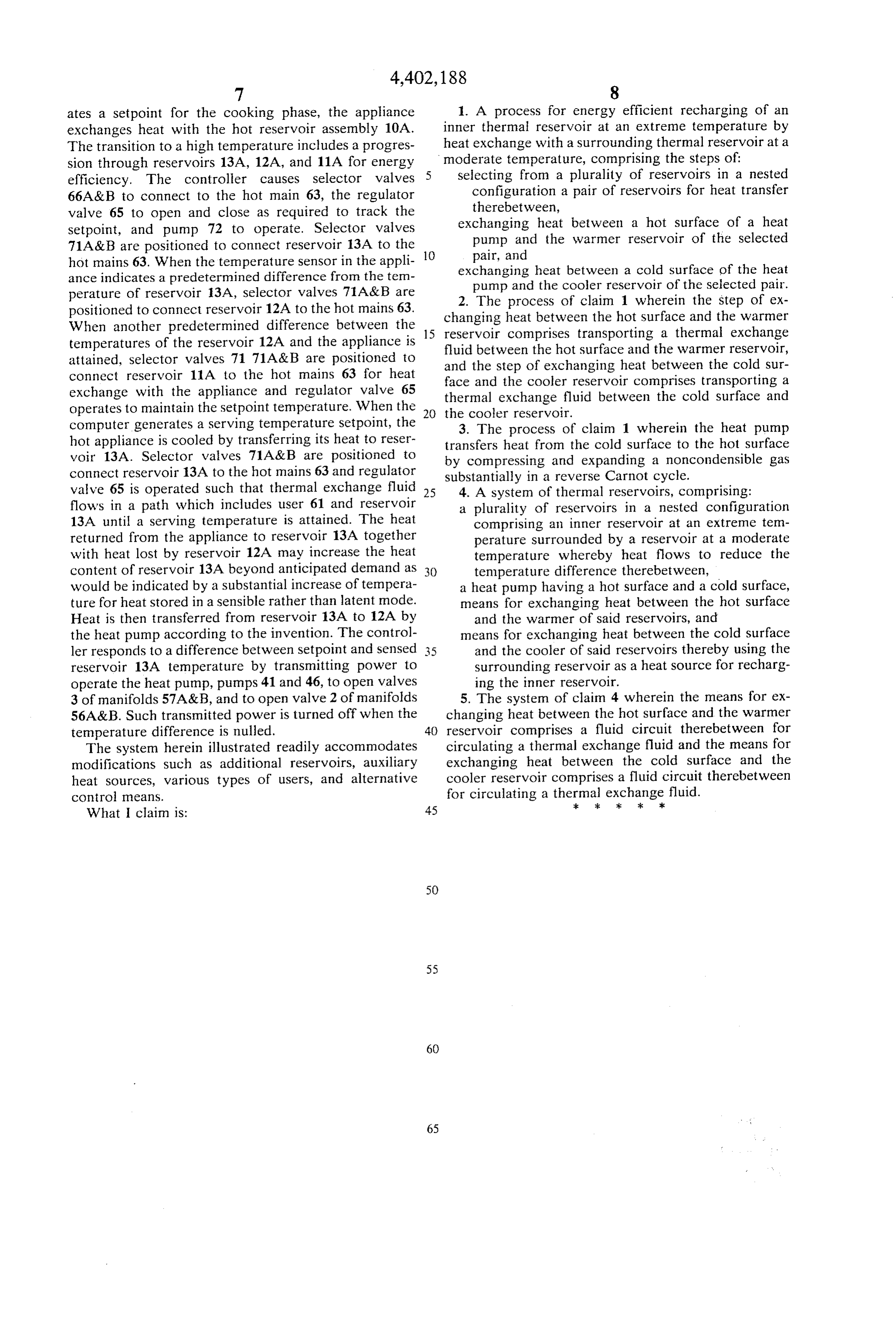
ates a setpoint for the cooking phase, the appliance 1. A process for energy efficient recharging of an exchanges heat with the hot reservoir assembly 10A. inner thermal reservoir at an extreme temperature by The transition to a high temperature includes a progres heat exchange with a surrounding thermal reservoir at a sion through reservoirs 13A, 12A, and 11A for energy 5 moderate temperature, comprising the steps of: efficiency. The controller causes selector valves Selecting from a plurality of reservoirs in a nested 66A&B to connect to the hot main 63, the regulator configuration a pair of reservoirs for heat transfer valve 65 to open and close as required to track the therebetween, setpoint, and pump 72 to operate. Selector valves exchanging heat between a hot surface of a heat 71A&B are positioned to connect reservoir 13A to the 10 pump and the warmer reservoir of the selected hot mains 63. When the temperature sensor in the appli pair, and ance indicates a predetermined difference from the tem exchanging heat between a cold surface of the heat perature of reservoir 13A, selector valves 71A&B are pump and the cooler reservoir of the selected pair. positioned to connect reservoir 12A to the hot mains 63. changing 2. The process of claim 1 wherein the step of ex When another predetermined difference between the 15 reservoir heat between the hot surface and the warmer temperatures of the reservoir 12A and the appliance is fluid between the hot transporting comprises surface and a thermal exchange the warmer reservoir, attained, selector valves 71 71A&B are positioned to and the step of exchanging heat between the cold sur connect reservoir 11A to the hot mains 63 for heat exchange with the appliance and regulator valve 65 thermal exchange fluid between the cold surface anda face and the cooler reservoir comprises transporting operates to maintain the setpoint temperature. When the computer generates a serving temperature setpoint, the 20 the3.cooler reservoir.
The process of claim 1 wherein the heat pump hot appliance is cooled by transferring its heat to reser transfers heat from the cold surface to the hot surface voir 13A. Selector valves 71A&B are positioned to by compressing and expanding a noncondensible gas connect reservoir 13A to the hot mains 63 and regulator substantially in a reverse Carnot cycle. valve 65 is operated such that thermal exchange fluid 25 4. A system of thermal reservoirs, comprising: flows in a path which includes user 61 and reservoir a plurality of reservoirs in a nested configuration 13A until a serving temperature is attained. The heat comprising an inner reservoir at an extreme tem returned from the appliance to reservoir 13A together perature surrounded by a reservoir at a moderate with heat lost by reservoir 12A may increase the heat temperature whereby heat flows to reduce the content of reservoir 13A beyond anticipated demand as 30 temperature difference therebetween, would be indicated by a substantial increase of tempera a heat pump having a hot surface and a cold surface, ture for heat stored in a sensible rather than latent node. means for exchanging heat between the hot surface Heat is then transferred from reservoir 13A to 12A by and the warmer of said reservoirs, and the heat pump according to the invention. The control means for exchanging heat between the cold surface ler responds to a difference between setpoint and sensed 35 and the cooler of said reservoirs thereby using the reservoir 13A temperature by transmitting power to surrounding reservoir as a heat source for recharg operate the heat pump, pumps 41 and 46, to open valves ing the inner reservoir. 3 of manifolds 57A&B, and to open valve 2 of manifolds 5. The system of claim 4 wherein the means for ex 56A&B. Such transmitted power is turned off when the changing heat between the hot surface and the warmer temperature difference is nulled. 40 reservoir comprises a fluid circuit therebetween for The system herein illustrated readily accommodates circulating a thermal exchange fluid and the means for modifications such as additional reservoirs, auxiliary exchanging heat between the cold surface and the heat sources, various types of users, and alternative cooler reservoir comprises a fluid circuit therebetween control means. for circulating a thermal
exchange
fluid.
What I claim is: 45
Provenance
- Collection
- Cited prior art
- Original PDF
- patentimages.storage.googleapis.com →
- Filed
- 1981-10-01
- Pages
- 7
- Method
- pdftotext (the PDF's own text layer) + pdftoppm 300dpi page scans
- Source
- Google Patents bibliographic record
- Granted
- 1983-09-06
- Inventors
- Stephen F. Skala
- Transcribed from
- patentimages.storage.googleapis.com →