patent · US4237864
Focusing solar collector
9 December 1980
Page 1 — bibliographic record
United States Patent (19) (11) 4,237,864 Kravitz (45) Dec. 9, 1980 (54. FOCUSING SOLAR COLLECTOR FOREIGN PATENT DOCUMENTS 76 Inventor: Barry Kravitz, 334 A. Thomas Rd., 2614545 8/1977 Fed. Rep. of Germany........... 126/438 Middleboro, Mass. 02324
Primary Examiner-Carroll B. Dority, Jr.
(21) Appl. No.: 906,103 Assistant Examiner-Larry Jones - Attorney, Agent, or Firm-Andrew T. Karnakis; Frank 22 Filed: May 15, 1978 J. Fleming 51 Int. Cl'................................................. F24J 3/02 57 ABSTRACT 52 U.S.C. ..................................... 126/425; 126/438 A focusing solar collector which utilizes an elongated 58) Field of Search ............... 126/270, 271, 425, 424, parabolic shaped mirror made from a sheet of drapable 126/438,451, 439, 419; 350/295, 310; 353/3 material so that when draped in a catenary like curved 56) References Cited configuration, the sun's rays may be focused on a linear
ror. Means are provided for adjusting the angle of the 3,445,157 5/1969 Zitter ................................... 350/295 drape of the catenary like curve in order to maintain the 3,574,447 4/1971 Ruble ................ ... 350/295 focus of the sun's rays on the linear target as the relative 3,893,755 7/1975 Cobarget al. ....................... 350/295 diurnal position of the sun to the collector changes. The 3,923,039 12/1975 Fabel ................................... 26/424 optimum catenary like curve for the range of the drape 3,972,600 8/1976 Cobarg................................. 350/295 angles involved is achieved by using a non-linear distri 4,015,585 4/1977 Fattor ........... ... 126/438 X bution of weight along the cross-section of the draped 4,046,462 9/1977 Fletcher et al. ..................... 350/295 mirror material.
4,106,481 8/1978 Van Kuijk ... ... 126/425 4,111,184 9/1978 Perkins .......... ... 126/425 4,134,387 1/1979 Tornstron ........................... 126/438 9 Claims, 5 Drawing Figures
Page 2
Drawing sheet — no readable text.
Page 3
Drawing sheet — no readable text.
Page 4
Drawing sheet — no readable text.
Page 5
Drawing sheet — no readable text.
Page 6
focused onto a rigidly mounted target. In addition, the
FOCUSING soLAR COLLECTOR target should be mounted in a position which does not block the path of the sun's rays received by the mirror.
FIELD OF THE INVENTION In the discussion of the prior art, it was pointed out This invention relates to an improved solar collector. 5 that a spherical parabolic mirror made of a plastic film More particularly, this invention relates to a focusing could be brought into focus on a target by applying air solar collector of the type utilizing an elongated para pressure and then made into a rigid mirror. No sugges bolic shaped mirror. tion was made that air pressure could be utilized as a means for automatically controlling the focus of the
DESCRIPTION OF THE PRIOR ART 10 mirror. If air pressure were used for automatically fo An example of a focusing solar collector which uti cusing an aluminized plastic film, it would require a lizes an elongated parabolic mirror is disclosed in U.S. supply of air under pressure and the controls for apply Pat. 2,247,830 issued on July 1, 1941 to C. G. Abbott. ing a pressure to the mirror. It is not obvious how the The Abbott solar collector discloses a mirror having a 15 same principle could be applied to shape an elongated rigid shape. parabolic mirror. For example, a cylindrically shaped The book "Direct Use of the Sun's Energy” by Far mirror might readily be adjusted in diameter by air rington Daniels, 1964 edition, describes on pages 42-57 pressure. However, the stretching of the plastic film a number of focusing solar collectors. The author de results in a substantial reduction in the reflectivity of the scribes the use of aluminized plastic film for the reflec 20 aluminized surface. It is therefore an advantage to be tive surface. However, the aluminized plastic film is able to adjust the focus of a mirror made of aluminized applied to the surface of a rigid parabolic form. He also plastic film without stretching the plastic film or requir cites an example of using air pressure to stretch a plastic ing a source of air under pressure and the controls es film into a spherical form as a means of adjusting the sential to controlling the inflation pressure. focus during the process of building a rigid mirror. He It is an object of this invention to provide a novel then points out that when an aluminized plastic film is 25 focusing solar collector which has a light weight para stretched, the stretching reduces it reflectivity apprecia bolic shaped mirror adapted to be focused on a target. bly. It is a further object of this invention to provide a Other prior art of general interest are the following novel focusing solar collector which has a light weight U.S. Pat. Nos.: parabolic shaped mirror having an adjustable shape for
4,000,734 issued Jan. 4, 1977 to Matlock; maintaining the focus on the target for changing posi 4,015,585 issued Apr. 5, 1977 to Fattor; tions of the sun with respect to the collector. 4,022,188 issued May 10, 1977 to Cohen et al. It is another object of this invention to provide a novel focusing solar collector which has a light weight
The prior art cited above is representative of the state parabolic of the art with respect to focusing solar collectors in so 35 cused shaped mirror adapted to be adjustably fo far as it applies to the present invention. All prior art on a rigidly mounted target. focusing solar collectors use mirrors having rigid It is a still further object of this invention to provide shapes. a novel focusing solar collector having a mirror which is inexpensive to construct.
DESCRIPTION OF THE INVENTION 40 It is still another object of this invention to provide a Before describing the present invention, several of novel focusing solar collector which requires a mini the design problems solved by the invention will be mum amount of energy to operate.
discussed. The objects of this invention are achieved by forming The energy absorption capacity of a solar collector is a novel elongated parabolic mirror by draping an alumi proportional to the absorption area upon which the 45 nized plastic film to form a modified catenary curve. solar energy is received. In order to be practical, a solar Inasmuch as no rigid form is used, the parabolic mirror collector must have a relatively large energy absorption is inexpensive to make and light weight. area. A solar collector having an elongated parabolic The term "catenary' is defined as the curve assumed mirror of a rigid shape is consequently relatively large by a cord when the cord is uniformly loaded along its and heavy, requiring a relatively expensive and power 50 length. In the case of a very flat arc produced by a taut ful focusing mechanism. Therefore, there is an advan cord, the equation for such a catenary curve closely tage to providing a design which has a light weight approximates that equation for a parabola. The inven mirror so that the focusing mechanism required is rela tion departs from the above definition in two ways. tively less expensive and less powerful. First, the elongated parabolic mirror is formed by drap The cost of producing an elongated parabolic mirror 55 ing a plastic film, thus adding a width dimension not having a rigid shape includes the cost of the rigid form found in a cord. Secondly, for the axis of the parabola to and the cost of preparing the reflecting surface. When be aligned with to the sun's rays, the angle of drape is an aluminized plastic film is used for the reflecting sur greater than that at which a suspended cable will ap face, the cost also includes the film and the mounting of proximate a parabolic curve. Therefore, the cross-sec the film. Therefore, there is an obvious cost advantage 60 tion of the pliable film is made non-uniform so as to in being able to use an aluminized plastic film without compensate for the range of angles through which the the need for a rigid form or the cost of mounting the plastic film may be moved in order to maintain the focus film on the rigid form. of the rays on a rigidly mounted target which is located In most focusing collectors, the target is rigidly so that it does not block the path of the rays received on mounted so as to avoid the need for movable joints 65 the reflective surface of the mirror.
through which the heated medium must pass as it con The adjustment for focusing the rays on the target veys the heat collected to other apparatus. Therefore, may be performed either manually or automatically. the focusing mirror structure must be such that it can be The automatic control system is preferably one which is
Page 7
actuated by sensing elements located in the proximity of The angle 01 of the sun's rays 32 from horizontal de the target so as to maintain a focusing position which pends upon the latitude at which focusing solar collec directs the maximum available energy to the target area. tor 10 is located, the season of the year and the time of DESCRIPTION OF THE DRAWINGS the day. At a latitude of 40, for example, the useful 5 range of angle 61 may vary from 10 degrees in the win
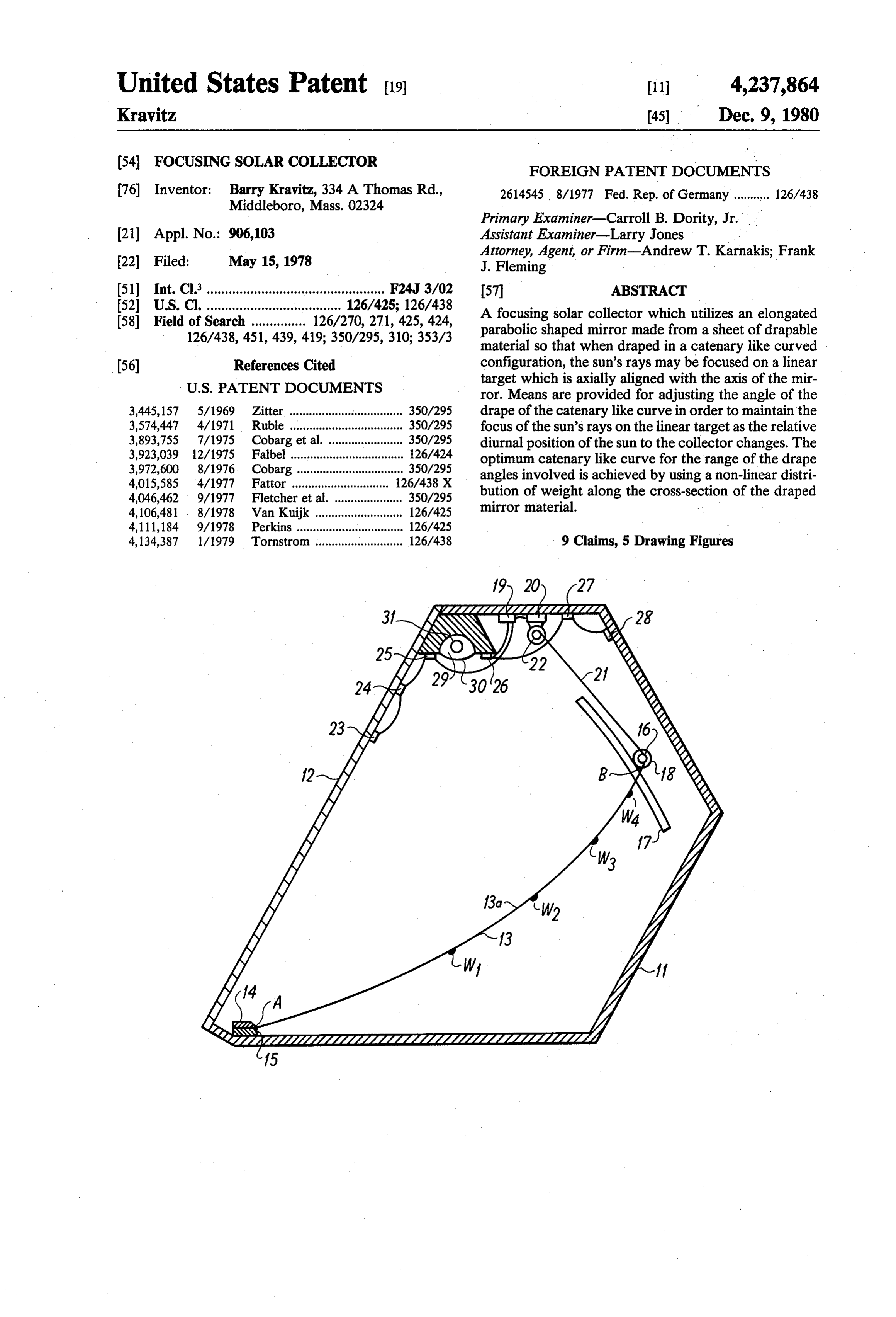
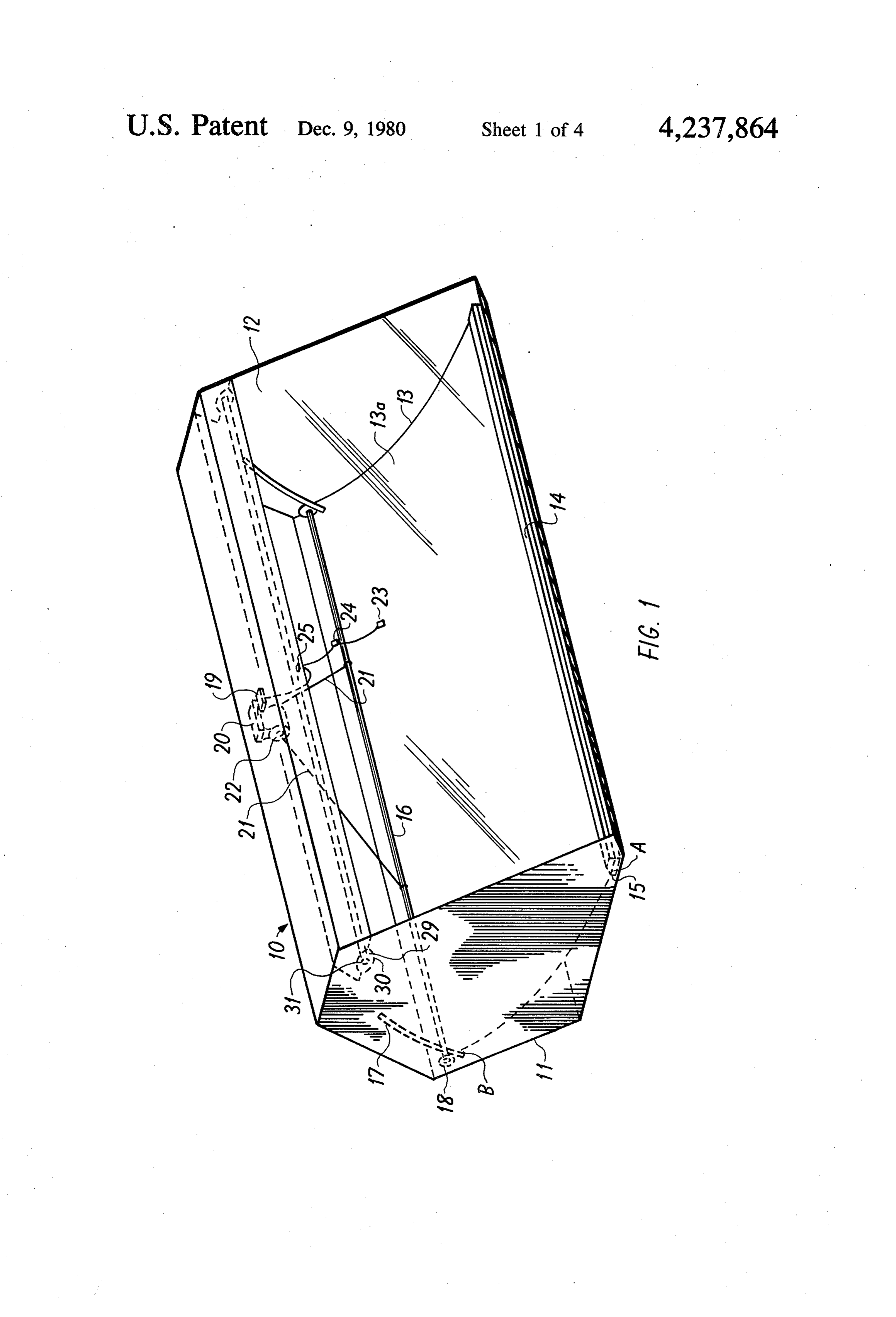
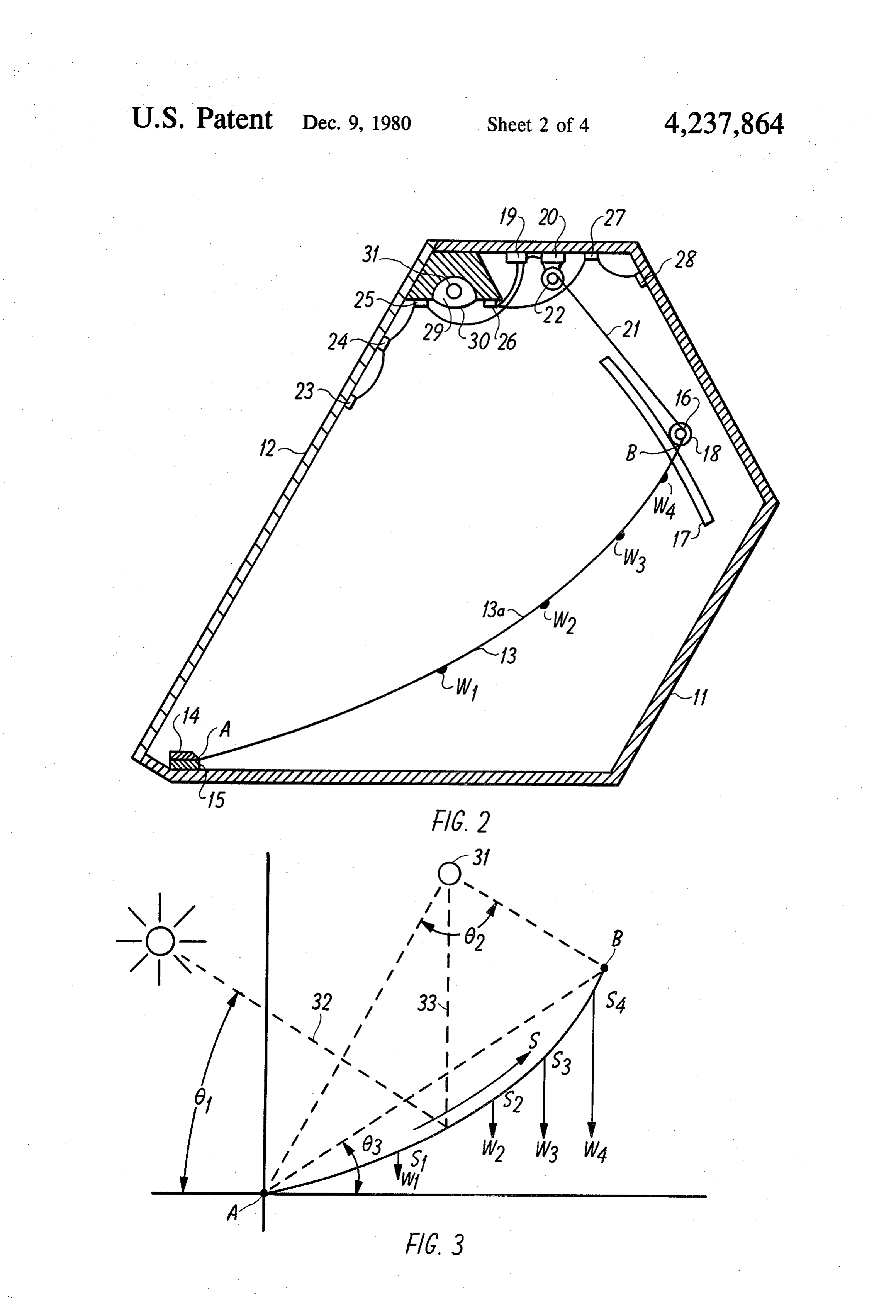
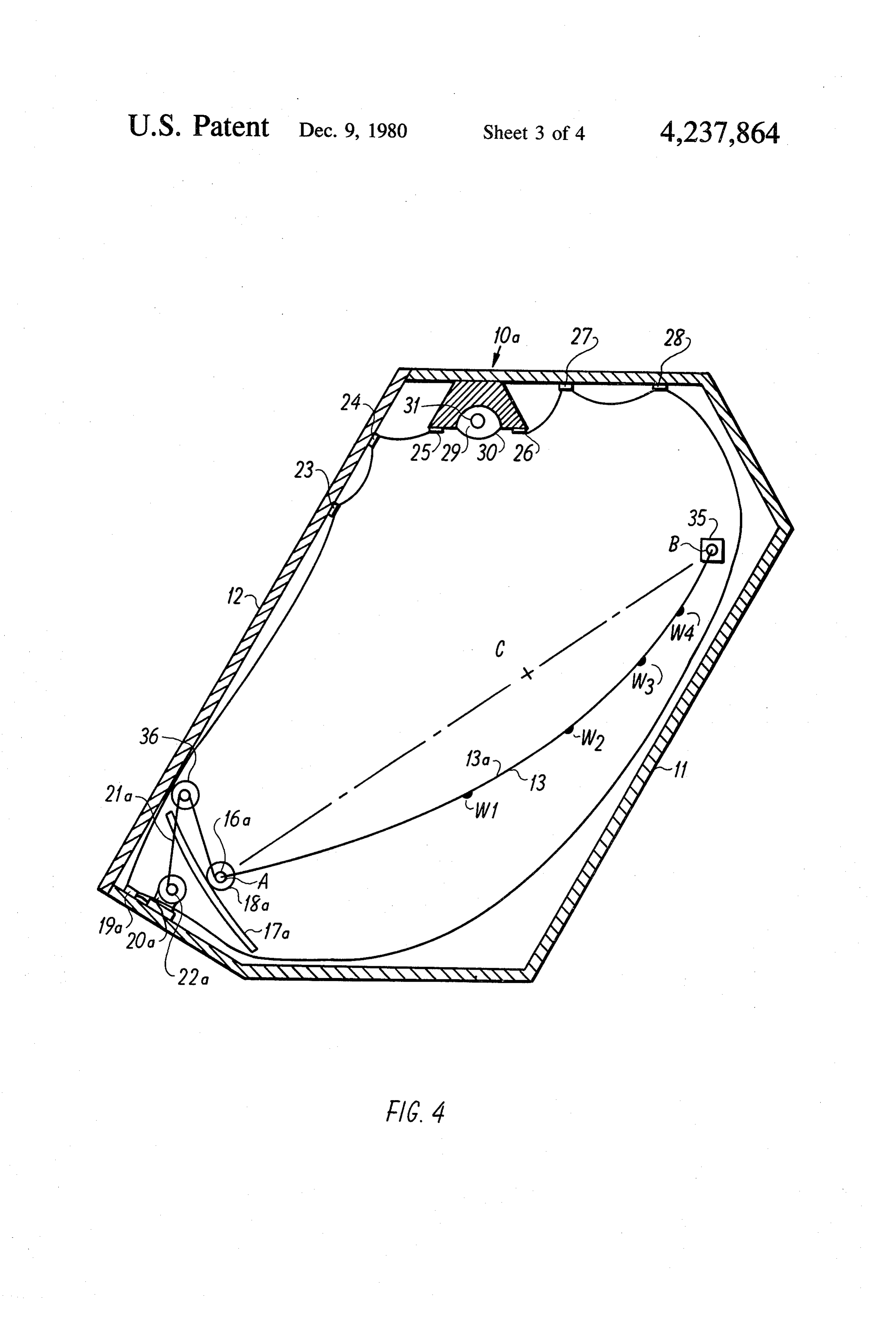
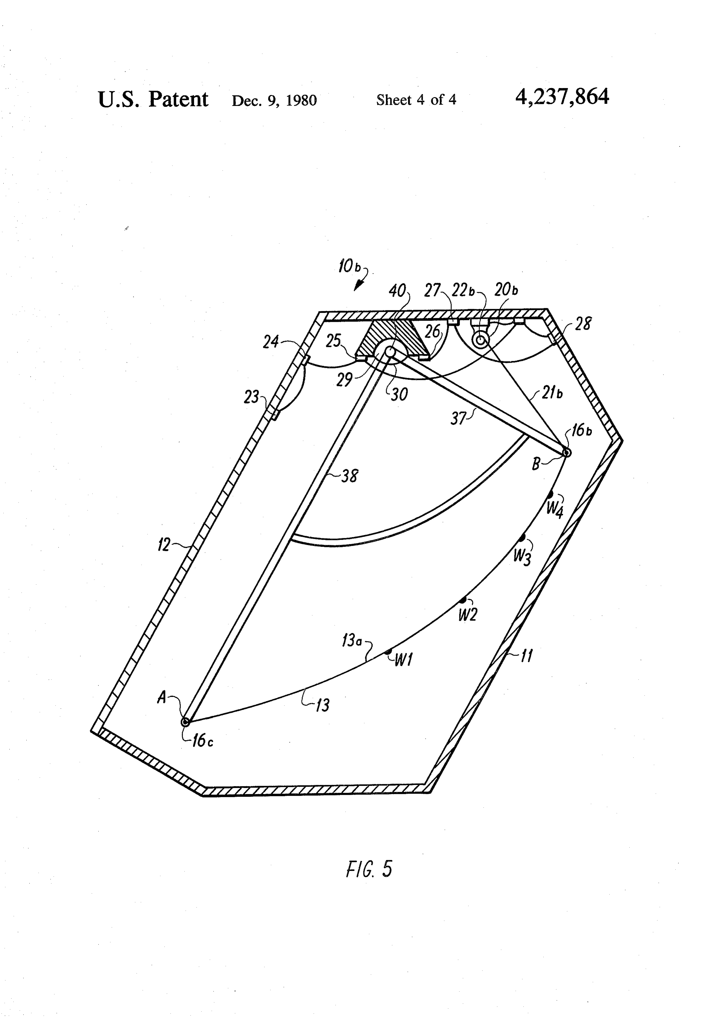
An understanding of the general nature of this inven ter to 73.5 degrees in the summer. Therefore, in order tion and an appreciation of its many advantages will be that the sun' rays 32 which impinge on mirror surface gained from a study of the following description given 13a of drapable material 13 will be reflected along path in connection with the drawings in which: 33 to impinge on black body 31, the drapable material FIG. 1 is a perspective view of the focusing collector. O 13 must assume a shape which is substantially parabolic FIG. 2 is a cross-sectional view taken from the right regardless of the drape angle 63 represented by a line end of the view in FIG. 1. through the edges A and B of drapable material 13. The FIG. 3 is a cross-sectional diagram of the aluminized edges A and B of drapable material 13 are located to plastic film which forms the adjustable mirror. present an effective mirror surface within a rim angle FIG. 4 is a cross-sectional view similar to FIG. 2 5 62 of 90 degrees, which is equal to one half of a para showing means for adjusting the drape angle of the bolic curve.
aluminized plastic film by adjusting the position of the When the drape angle 03 is zero degrees, drapable lower edge thereof. material 13 will assume a parabolic curve provided it is FIG. 5 is a cross-sectional view similar to FIG. 2 taut and uniformly loaded between edges A and B; i.e. showing means for adjusting the drap angle of the alu 20 is uniform in thickness. However, the further the drape minized plastic film by adjusting both edges thereof. angle 63 departs from zero degrees, the greater the DESCRIPTION OF PREFERRED departure of the assumed curve will be from a true EMBODIMENTS parabola. In order to cause the drapable material 13 to assume a curve which is substantially parabolic when
Referring to FIGS. 1 and 2, the focusing solar collec 25 the drape angle 63 departs from zero degrees, the drap tor 10 of this invention is enclosed in casing 11, which able material 13 is provided with some slack and a series has a transparent panel 12 along one side thereof of weights W1-W4 are attached longitudinally to drap through which the rays of the sun pass to impinge on able material 13 at empirically selected distances from the reflective surface 13a of a sheet of drapable material edge B and with empirically selected weights to pro 13. Drapable material 13 may be a plastic film having 30 duce a nonuniform weight distribution of drapable ma one surface aluminized to provide a reflective surface terial 13 between edges A and B. The weight of weights 13a. Drapable material 13 is attached at its lower edge W1-W4 and their location necessary to produce the para by cleat 14 to the upper surface of rib 15, which is bolic shape varies as the drape angle 63 varies. There mounted on the inner surface of casing 11. Thus the fore, the selection of the best combination of weights mounted edge of drapable material 13 is raised by rib 15 35 W1-W4 and their location on drapable material 13 may above the surface of casing 11. The upper edge of drap be for a range of drape angles 63 best for the principle able material 13 is attached to bar 16. Thus drapable purpose of the focusing solar collector. For example, at material 13 extends parallel to the longitudinal axis of 40 degrees latitude, the range of the drape angle 03 for casing 11 and drapes at an angle to the horizontal axis of providing heat during the winter months might be from: casing 11. On each end of casing 11 is mounted arced 40 10 to 50 degrees.
track 17 arranged so that rollers 18 rotatively mounted Referring to FIGS. 1 and 2, drape angle 63 is auto on each end of bar 16 will travel along the upper surface matically adjusted by positioning motor 20. Sensing of arced track 17. The center of an arced track 17 is on elements 23, 24, 25, 26, 27 and 28 are protected from the the axis parallel to the lower edge of drapable material direct rays of the sun and are conncted to control circuit 13. 19 so that when the path 33 of the reflected rays ener
Mounted on the inner surface of casing 11 in a central gizes any one of sensing elements 23, 24 and 25 more position near the top thereof are control circuit 19 and than sensing elements 26, 27 and 28, then positioning positioning motor 20. One end of cord 21 is attached to motor 20 unwinds cord 21 to lower bar 16 along arced. pulley 22 of positioning motor 21 and the other end track 17 until the energization of each group of sensing thereof to bar 16. Sensing elements 23, 24 and 25 are SO elements has equalized. In like manner, when any one of connected to control circuit 19 and sensing elements 26, sensing elements 26, 27 and 28 is energized more than 27, and 28 (not show in FIG. 1, see FIGS. 2, 4 and 5) are sensing elements 23, 24 and 25, positioning motor 20 also connected thereto. winds up cord 21 to raise bar 16 along arced track 17 Mounted longitudinally within casing 11 in the space until the energization of each group of sensing elements adjacent the upper edge of the transparent panel 12 55 has equalized. Thus, the path 33 of the reflected rays of parallel to the longitudinal axis of casing 11 is target the sun is maintained focused on black body 31. chamber 29 which is covered by transparent panel 30 to FIG. 4 shows focusing solar collector 10a in which provide a "green house' effect. Within chamber 29 is lower edge A of drapable material 13 is moved while mounted black body 31 which absorbs the energy of the upper edge B in maintained in a fixed position. Lower sun's rays and is adapted to transfer that energy to other 60 edge A of drapable material 13 is attached to bar 16a. At apparatus (not shown). By way of example, black body each end of casing 11 is mounted arced track 17a ar 31 may be a conduit through which either air or water ranged so that rollers 18a rotatively mounted at each flows and absorbs energy for transfer to the other appa end of bar 16a will travel along the upper surface of ratus for utilization. arced track 17a. The center C of the arc of arced track The operation of focusing solar collector 10 will now 65 17a is empirically selected for the range of drape angles be explained with reference to FIGS. 1, 2 and 3. The 63 for a particular focusing solar collector 10a. The mirror surface 13a of drapable material 13 is oriented so upper edge B of drapable material 13 is attached to bar that its longitudinal axis is at right angles to solar south. 35 which is mounted longitudinally in casing 11.
Page 8
Target chamber 29, transparent cover 30, black body solar rays and focusing said rays along a focal axis 31 and heat sensing elements 23, 24, 25, 26, 27 and 28 are parallel to said support means; located in the same position within casing 11 as in the an elongate absorber positioned at the focal axis of embodiment shown in FIGS. 1 and 2. said reflective surface;
Positioning motor 20a is mounted below arced track 5 means for moving one of said support means in re 17a. One end of cord 21a is attached to pulley 22a of sponse to the diurnal movement of the sun thereby positioning motor 20a and passes over pulley 36 at altering the shape of said material; and tached to the outer end of arced track 17a. The other said material being non-uniformly loaded along its end of cord 21a is attached to bar 16a. cross section such that when the shape is altered The operation of focusing solar collector 10a is the 10 the focus will be maintained at said focal axis. 2. The solar collector of claim 1 wherein said means same as that of focusing solar collector 10, except that for moving the lower edge A of drapable material 13 is moved as tain the focus. moves both of said support means to main the means for adjusting drape angle 63. 3. The solar collector of claim 1 including solar sens FIG. 5 shows focusing solar collector 10b on which 15 ing means and position control means responsive to said both ends A and B of drapable material 13 are moved solar sensing means for adjusting the shape of said mate simultaneously. Upper rod 16b is attached to upper edge rial to maintain the focus on said focal axis over a range B of drapable material 13 and lower rod 16c is attached of solar elevation angles.
to the lower edge A of drapable material 13. Each of the 4. The solar collector of claim 3 wherein said solar rods 16b and 16c is mounted on arms 37 and 38 respec 20 sensing means comprise two sets of sensors, each set on tively of frame 39. Positioning motor 20b is mounted on opposite sides of said focal axis; the upper surface of casing 11. One end of cord 21b is said position control means responding to an unbal attached to pulley 22b of positioning motor 20b. The ance in signal intensity from each set and moving other end of cord 21b is attached to bar 16b. said one support means until a balanced condition Target chamber 29, transparent cover 30, black body 25 is achieved thereby maintaining the focus on said 31 and sensing elements 23, 24, 25, 26, 27 and 28 are focal axis.
mounted in the same positions within casing 11 as in the meansThe 5. solar collector of claim 1 including housing encasing both of said support means and said embodiments shown in FIGS. 1 and 2. In this FIG. 5, flexible black body 31 is indicated as hidden by pivot 40 of 30 ent panelmaterial, said housing means having a transpar for admitting solar rays.
frame 39.
The operation of focusing solar collector 10b is the means6. The solar collector of claim 1 including solar targe
same as that of focusing solar collector 10, except that 7. The solar collector of claim 6 including housing both the lower edge A and upper edge B of drapable means encasing both of said support means, said flexible material 13 are moved simultaneously as the means for 35 material and said solar target means, said housing means adjusting drape angle 63. having a transparent face for admitting solar rays. I claim: 8. The solar collector of claim 1 wherein said flexible 1. A tracking solar collector comprising: material comprises a plastic film with an aluminized first and second elongate support means positioned reflective surface.
apart from one another with their longitudinal axes 40 9. The solar collector of claim 1 wherein the shape of generally parallel; said flexible material is maintained along a parabolic a sheet of flexible material suspended between said CtWe. sk k k sk support means having a reflective surface receiving
Provenance
- Collection
- Cited prior art
- Original PDF
- patentimages.storage.googleapis.com →
- Filed
- 1978-05-15
- Pages
- 8
- Method
- pdftotext (the PDF's own text layer) + pdftoppm 300dpi page scans
- Source
- Google Patents bibliographic record
- Granted
- 1980-12-09
- Inventors
- Barry Kravitz
- Transcribed from
- patentimages.storage.googleapis.com →