patent · US5513793
Brazeless ceramic-to-metal bond for use in implantable devices
7 May 1996
Page 1 — bibliographic record
United States Patent (19) 11) Patent Number: 5,513,793 Malmgren (45) Date of Patent: May 7, 1996 54 BRAZELESS CERAMIC-TO-METAL BOND 4,861,641 8/1989 Foster et al. ..... a 428/137 FOR USE IN MPLANTABLE DEVICES 4,882,298 11/1989 Moeller et al. .. ... 437/212 4,906,311 3/1990 Gurol .................................... 156/89 75 Inventor: Richard P. Malmgren, Castaic, Calif. 4,991,582 2/1991 Byers et al. ... 128/49 P 5,181,647 1/1993 Runyan .................................. 228/44.3 73) Assignee: Advanced Bionics Corporation, FOREIGN PATENT DOCUMENTS Sylmar, Calif.
(21) Appl. No.: 319,580 Primary Examiner Samuel M. Heinrich 22 Filed: Oct. 7, 1994 Attorney, Agent, or Firm-Fitch, Even, Tabin & Flannery
52 U.S. C. ................. 228/193; 228/212; 228/262.21 In a method and apparatus for forming a hermetically sealed (58) Field of Search ..................................... 228/190, 193, bond for use in implantable medical devices, a first structure, 228/195, 124.6, 212, 262.21, 262.71 made from a first material, is positioned against a second structure, made from a second material. A compressive force 56) References Cited directed at the second structure is applied to the first struc
direction opposite the compressive force is applied to the
Re. 33,859 3/1992 Gurol ........................................ 428/76 second structure so that the first and second structures are 4,041.955 8/1977 Kelly et al. ... ... 128/419 P isodynamically pressed together. The first and second struc 4,159,075 6/1979 Ljung et al. ............................ 228/116 tures are heated to a diffusion temperature whereat the first 4,525,766 6/1985 Petersen .................................. 361/283 material and the second material undergo diffusion, thereby 4,618,802 10/1986 Schrank .... ... 313/512 forming a hermetically sealed bond between the first and 4,627,958 12/1986 Hays ........................................... 41.9/8 second materials.
4,693,409 9/1987 Mizunoya et al. 228/262.21 4,725,480 2/1988 Gurol ...................................... 428/210 4,729,504 3/1988 Edamura ............................ 228/262.72 15 Claims, 2 Drawing Sheets
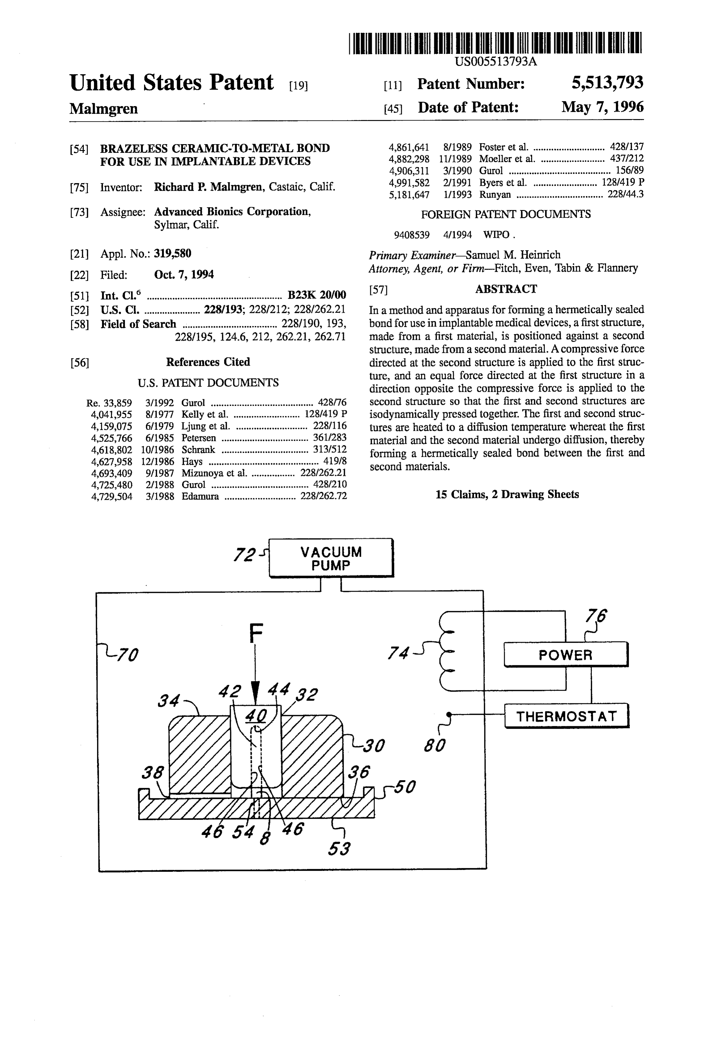
THERMOSTAT
Page 2
Drawing sheet — no readable text.
Page 3
Drawing sheet — no readable text.
Page 4
BRAZELESS CERAMC-TO-METAL BOND the electronics housed in the implantable package. Thus FOR USE IN MPLANTABLE DEVICES configured, the closed metal loop or solder acts as a shunt to the alternating electromagnetic fields impressed upon the package to transmit power and/or data to the implanted
BACKGROUND OF THE INVENTION 5 electronics. This has resulted in the generation of undesired The present invention relates to bonding of materials, and heat within the package and the reduction of power transfer efficiency.
more particularly to brazeless bonding of dissimilar mate rials. Even more particularly, the present invention relates to A packaged combination of one ceramic and two metal brazeless hermetically sealed bonding of ceramic to metal members is shown in U.S. Pat. No. 4,991,582, issued to for use in implantable devices. 10 Byers et al. and incorporated herein by reference. The one stimulators that are to be implanted in living bodies and ceramic member is a ceramic case and one of the metal powered from external informational sources must be members is a metal band. The other metal member is a housed in packages of biocompatible material. Such pack header plate. The ceramic case and the metal band are ages must protect the electronic circuitry within the hermetically sealed together, each being characterized by implanted stimulator from body fluids and ions so that the 15 similar coefficients of linear thermal expansion. The final circuitry can survive for extended periods without any package closure is effected by soldering the metal band to significant changes in performance. the ceramic case and the metal header plate to the metal band.
Today, the most commonly used metals for implantable packages are titanium, stainless steel and cobalt-chromium 20 The junction between the ceramic case and metal band alloys. These metals are biocompatible and corrosion resis includes a bond of flat and smooth non-interlocking geom tant. Normally, the package consists of two parts welded etries. By such a design, forces resulting from unequal together to insure hermeticity. The electrical components expansion or contraction of materials in or near the junction inside the package are connected to stimulating leads by of the ceramic and metal members during temperature hermetic feedthroughs, which permit the flow of electrical 25 changes within and about the package are very inefficiently currents through the package while maintaining hermeticity. transferred to the ceramic members. This reduces the risk of However, where there is a need to inductively couple an residual strain and ultimately of fractures in the ceramic. alternating electromagnetic field to an internal pickup coil, Alternatively, where the coefficients of linear thermal the metal package becomes a hinderance. Specifically, trans expansion of the ceramic case and metal band are similar, mission of power is substantially reduced by eddy currents 30 i.e., very close, the junction between the ceramic case and generated in the metal package due to the alternating elec metal band may be interlocking to effect a self-jigging of the tromagnetic field. To solve that problem, receiving coils are members during assembly. In such a form, temperature often placed outside the metal package, increasing the size changes will produce corresponding changes in the geom and complexity of the of the implanted device. etries of the ceramic and metal members and undesired It is known that the glasses and ceramics are transparent 35 stresses on the junction will be minimized. to alternating electromagnetic fields and that receiving More particularly, the ceramic case shown in the '582 antennas can be placed inside a hermetic zone of a ceramic patent consists of a hollow flattened ceramic sleeve having or glass package, creating an overall smaller and simpler a closed end and side walls and an open end for receiving implant device and reducing the possibility of antenna electronic components of an implantable device, which are failure due to saline leakage. Glasses and ceramics are inert 40 adversely sensitive to high temperatures such as those and highly insoluble, which are favorable characteristics for components that receive and transmit electromagnetic long term implant materials. Unfortunately, however, energy from or to the outside of the package. The coils because glasses and ceramics are inelastic, they are subject comprising the antenna are positioned within the ceramic to fracture not only from mechanical shock but also from sleeve remote from and in a plane transverse and preferably differential thermal expansion if even a moderate tempera 45 normal to a flat annular end surface around the open end of ture gradient exists thereacross. Therefore, welding is not a the ceramic sleeve where the metal band is bonded. The practical method of sealing glass or ceramic materials. metal band has a flat annular edge hermetically sealed as by Instead, virtually the entire package and its contents must be a biocompatible metallic braze or glass solder to the flat raised to the melting temperature of the glass, ceramic or annular end surface of the ceramic sleeve. Thus configured, metal braze used to effect a sealing of the glass or ceramic 50 the closed metal loop formed by the metal band and/or metal package. Such sealing methods are unsatisfactory. solder does not act as a shunt to power and/or information All known biocompatible glasses and ceramics are char conveying alternating electromagnetic fields impressed acterized by high sealing temperatures that will damage upon the package and antenna of the present invention. electronic components commonly included in electronic Finally, the header plate closes the package by means of devices implanted in living bodies. Low melting tempera 55 an hermetic bond to the metal band. The header plate carries ture glasses all have the property of being corroded by body a plurality of electrical feedthrough connectors for connect fluids. Further, metal or glass frits and soldiers useful in ing electrical leads to the electronic components within the brazing glasses and ceramics and having melting tempera package. The metal sleeve is bonded by high temperature tures below the thermal damage limits of implanted elec welding, such as electron beam or laser welding, to the metal tronic components are either not biocompatible or corrode 60 band after the electrical components are mounted in the easily in body solutions. Therefore, packages composed ceramic sleeve (or case) and adequate heat sinking is applied entirely of ceramic and/or glass are not considered practical to insure that there is no heat transfer to any heat sensitive for such implant applications. electronic components or ceramic package component dur Also, in many ceramic and glass packages, the metal ing the hermetic Sealing operation.
solder used to seal the main body and cap portions thereof 65 Unfortunately, the package shown in the '582 patent still forms a closed loop that is very close to coaxial with, or in requires the use of a hermetically sealed weld or solder joint a plane parallel to, the receiving coil used as the antenna for between the ceramic case and the metal band that suffers
Page 5
from one or more the following problems: (a) lack of a closed end against which the first structure can be seated. biocompatability; (b) lack of corrosion resistance; (c) lack of The outer jig has an open-ended cavity having inner walls electrolytic compatibility; (d) susceptibility to cracking of that slidably engage the outer walls of the inner jig. When the ceramic case; and/or (e) toxicity. Thus, improvements the outer walls of the inner jig are slidably engaged against are needed to overcome these problems with hermetically 5 the inner walls of the outer jig, movement of the inner jig is sealed bonds of ceramic to metal in packages for implant restricted to be along a single coordinate axis. able devices. The support surface has a substantially planar surface against which the outerjig is supported, and that is substan
SUMMARY OF THE INVENTION tially normal to the single coordinate axis. Before the inner 10 jig is slid into the outer jig, a second structure is interposed
The present invention advantageously addresses the needs between the first structure and the support surface. The above as well as other needs by providing an apparatus and second structure may be inserted into the open end of the method for forming a brazeless hermetically sealed bond. inner jig's cavity, and seat against the first structure therein, The invention may be characterized as a method of end or may seat against the first structure at or outside the open forming the hermetically sealed bond between materials. 15 the first of the inner jig's cavity. Such will depend on whether The method includes positioning a first structure, made from jig's cavity structure protrudes through the open end of the inner a first material, against a second structure, made from a when the first structure seats against the closed second material. A compressive force directed at the second end of the inner jig's cavity.
structure is applied to the first structure, and an equal force The compression means applies a compressive force directed at the first structure in a direction opposite the 20 applied structure against the inner jig, which is translated to the first by the inner jig. The compressive force is oriented compressive force is applied to the second structure so that toward the planar surface along the single coordinate axis. the first and second structures are isodynamically pressed The compression means further applies an equal force together. opposite the compressive force to the support surface. The Next, the first and second structures are heated to a support surface translates the equal force to the second diffusion temperature whereat the first material and the 25 structure so as to isodynamically compress a bonding junc second material undergo diffusion, thereby forming a her tion between the first and second structures. metically sealed bond between the first and second materi The heating means heats the first and second structures to als. In this way, the hermetically sealed bond is formed a diffusion temperature. At the diffusion temperature, a first between the first and second structures. material in the first structure and a second material in the In one embodiment, the first structure is inserted or slid 30 second structure undergo diffusion. As a result, a hermeti into a cavity of an innerjig through an open end of the cavity cally sealed bond is formed between the first and second until the first structure seats against a closed end of the structures.
cavity. Next, the second structure is placed against a portion It is therefore a feature of the invention to provide a of the first structure that is exposed through the open end of method and apparatus for forming a hermetically-sealed the cavity. The second structure may be partially inserted 35 bond between a first structure and a second structure.
into the cavity through the open end before it seats against It is another feature of the invention to form such her the first structure, or the second structure may seat against metically-sealed bond without the need for soldering. the first structure at or outside the open end. It is a further feature of the invention to form such An outer jig is placed against a support surface, and then hermetically-sealed bond while maintaining biocompatabil the inner jig is inserted into an open-ended cavity of the ity, corrosion resistance and electrolytic compatibility, and outerjig. Outer walls of the inner jig slide against inner walls eliminating toxicity.
of the outer jig's open-ended cavity so as to restrict the sliding of the inner jig to be along a single coordinate axis. It is an additional feature of the invention to form such The support surface lies in a plane substantially normal to 45 bond while minimizing the risk of cracking in the first and/or the single coordinate axis, with the open end of the inner second structures.
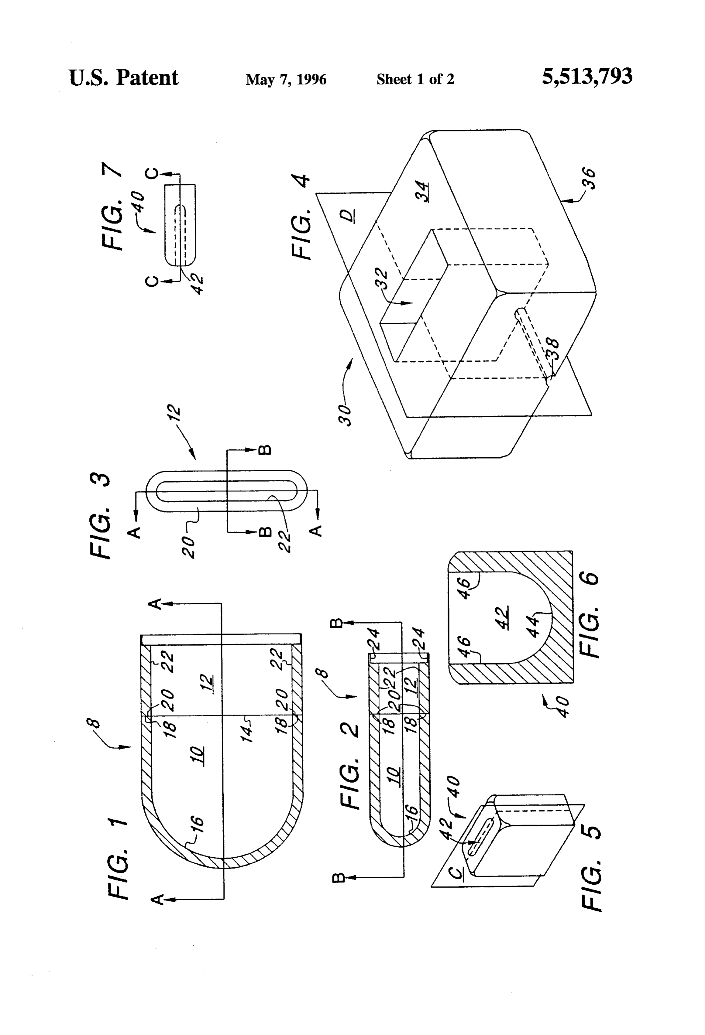
jig's cavity being oriented toward the plane and the closed BRIEF DESCRIPTION OF THE DRAWINGS end of the inner jig's cavity being oriented away from the plane. The second structure is also oriented toward the plane. The above and other aspects, features and advantages of As the inner jig is slid into the outer jig, the second 50 lowingthe present invention will be more apparent from the fol structure seats against the support surface. As a result, the more particular description thereof, presented in sliding of the inner jig into the outer jig is stopped. The conjunction with the following drawings wherein: compressive force is applied against the inner jig toward the FIG. 1 is a cross-sectional view of a case and a band support surface and along the single coordinate axis. The having been bonded together in accordance with one compressive force is translated to the first structure by the 55 embodiment of the invention taken along a first sectional closed end of the inner jig's cavity. The equal force is plane;
exerted by the support surface in the direction opposite the FIG. 2 is another cross-sectional view of the case and the compressive force, and is translated to the second structure band having been bonded together as in FIG. 1 taken along by the support structure. In this way, a hermetically sealed a second sectional plane that intersects line A-A of FIG. 1 bond is created between the first structure and the second and that is normal to the first sectional plane, which inter structure. sects line B-B in FIG. 2;
The invention may also be characterized as an apparatus FIG. 3 is an end view of the band of FIGS. 1 and 2 for forming a hermetically sealed bond between materials. showing a flat annular surface to which a similar flat annular The apparatus includes: an inner jig; an outerjig; a support surface of the case is bonded;
surface; compressing means; and heating means. 65 FIG. 4 is a perspective view of an outer jig that can be The inner jig has outer walls, and a cavity. The cavity has used in bonding together the case and band of FIGS. 1, 2 and an open end formed so as to receive a first structure, and has 3;
Page 6
FIG. 5 is a perspective view of an inner jig that can be for receiving a header plate (not shown). See, e.g., U.S. Pat. used in conjunction with the outer jig of FIG. 4 when No. 4,991,582, previously incorporated herein by reference. bonding together the case and band of FIGS. 1, 2 and 3; Referring next to FIG. 4, a perspective view is shown of FIG. 6 is a cross-sectional view of the inner jig of FIG. 5 an outer jig 30 that is used in bonding the case 10 and band taken along plane C of FIG. 5; 12 together. The outer jig 30 has generally a rectangular three
FIG. 7 is a side view of the inner jig of FIG. 5 shown therethrough. dimensional shape with a rectangular cavity 32 passing perpendicular to plane C of FIG. 5; The upper surface 34 is identical to the lower surface 36 except for a channel 38 in the lower surface 36
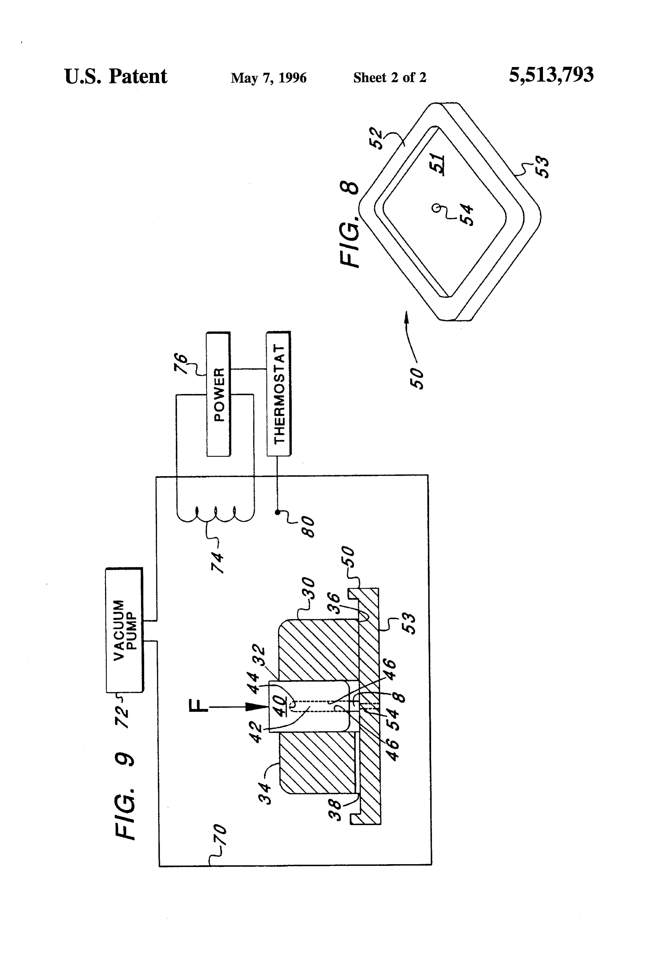
FIG. 8 is a perspective view of a support surface that is that passes from the center of one of the outer side edges of utilized in conjunction with the outer jig of FIG. 4 and the 10 the outer jig 30 to the center of one of the inner side edges innerjig of FIGS.5, 6 and 7 in bonding together the case and of the cavity 32. The channel 38 is also illustrated in FIG.9 band of FIGS. 1, 2 and 3; and and is explained more fully below. FIG. 9 is a partial cross sectional view of the outer jig of The dimensions of the outerjig 30 are dictated by the size FIG. 4, taken along plane D of FIG. 4, and the inner jig of and shape of the case 10 and band 12 that are bonded FIGS. 5, 6 and 7. 15 together. For the case 10 and band 12, shown in the figures, Corresponding reference characters indicate correspond the outer jig 30 is preferably made from ALUMINA, avail ing components throughout the several views of the draw able from ICI Advanced Ceramics, and has the following ings. outer dimensions: 8.97x7.06x3.81 cm. The dimensions of the cavity 32 are preferably: 3.89x1.98x3.81 cm, and the 20 channel preferably has a cross sectional area of 7.70 cm.
DETAILED DESCRIPTION OF THE The outer jig 30 preferably has beveled or rounded edges to INVENTION improve its appearance and to facilitate its handling. The following description of the presently contemplated Referring next to FIG. 5, a perspective view is shown of best mode of practicing the invention is not to be taken in a 25 30 inner an jig 40 that is used in conjunction with the outerjig limiting sense, but is made merely for the purpose of outerjig30, thetogether in bonding innerjig the case 10 and band 12. Like the 40 has generally a rectangular three describing the general principles of the invention. The scope dimensional shape. The innerjig 40 has a cavity 42 opening of the invention should be determined with reference to the on one of its sides that is formed so as to receive the case 10. claims.
When the case 10 is inserted into the cavity 42 it to is held
Referring first to FIG. 1, a cross-sectional view is shown 30 with all of the interior walls of the cavity 42 touching all of of a case 10 and aband 12 (or case/band assembly 8) having the exterior walls of the case 10.
been bonded together at a bonding site 14. Similarly, in For the preferred embodiment shown in the figures, the reference to FIG. 2, a cross-sectional view is shown of the inner jig 40 is preferably made from ALUMINA, available case 10 (or first structure) and the band 12 (or second from ICI Advanced Ceramics, and has the following outer structure) having been bonded together at the bonding site 35 dimensions: 3.81x1.90x3.81 cm so that the inner jig 40 can 14. The view shown in FIG. 1 is taken along line B-B be slid into the cavity 32 of the outerjig30. The innerjig 40 shown in FIG. 2, and the view shown in FIG. 2 is taken preferably has beveled or rounded edges to improve its along line A-A shown in FIG.1. In both FIGS. 1 and 2, the appearance and handling.
case 10 is shown as having a 'D' shaped cross section. Such cross section facilitates implantation and accommodates any 40 In practice, the case 10 is slid into the inner jig's cavity electronic components that are to be housed within the 42 until it becomes seated against a closed end 44 (FIG. 6) and side walls 46 (FIG. 6) of the cavity 2. After the case 10 case/band assembly 8, as well as one or more coils that can be housed within the case/band assembly 8. is slid into the cavity 42, the band 12 is slid into the cavity The case 10 is preferably made from a body-safe ceramic, 42 until the second flat annular surface 20 (FIGS. 1 and 2) e.g., Alumina (AlO) or Zirconium Oxide (ZO), and is open 45 of theagainst seats case the first flat annular surface 18 (FIGS. 1 and 2) 10. The band 12 protrudes from the cavity 42 at its straight end, i.e., the straight end of the "D" shape when it is seated against the case 10, as shown in FIG. 9 while its curved end and side walls are closed. Walls 16 of below.
the case 10 terminate around the open end forming a first annular surface 18. Referring to FIG. 6, a cross sectional view of the innerjig Referring next to FIG.3, an end view is shown of the band 50 6, shown
the taken along plane C of FIG. 5. As viewed in FIG.
cavity 42 in the inner jig 40 is substantially "D" 12 showing a second flat annular surface 20 (also shown in shaped so as to accommodate the "D"-shaped case/band FIGS. 1 and 2) to which the first flat annular surface 18 of assembly 8 of FIG. 1 (or case 10 and band 12, before they the case 10 is ultimately bonded. The band 12 is preferably are bonded together).
made from a body-safe metal, e.g., an alloy of Titanium-45
Niobium (i.e., 55%. Ti and 45% Nb), available from Tele 55 Referring next to FIG. 7, a side view is shown perpen dyne Wha Chang of Albany, N.Y., or numerous other dicular to plane C of FIG. 5 of the inner jig. The innerjig 40 sources, or any other metal or alloy that readily forms an is shown, and the cavity 42 is shown with dashed lines. The instant oxide when heated, i.e., that readily oxidizes when cavity 42 also has a "D" shaped cross section as viewed in heated in an oxygen-containing atmosphere. Note that both FIG. 7, which accommodates the "D"-shaped cross section the alumina and the Titanium-45 Niobium have thermal 60 of the case/band assembly 8 as viewed in FIG. 2 (or case 10 coefficients of expansion (TCEs) of between 8 and 9 mm/ and band 12, before they are bonded together). °C. This minimizes the risk of cracking when the case 10 and Referring next to FIG. 8, a perspective view is shown of band 12 are bonded together at high temperature and then a support surface 50 that is utilized in conjunction with the cooled. The band 12 has two open ends. Side walls 22 of the outer jig 30 and the inner jig 40 in bonding the case 10 and band case 12 terminate at each of the open ends, forming the 65 band 12. The support surface 50 has a lip 52 at the periphery second flat annular surface 20 at one of the ends, and having, of an upper side 51 of the support surface 50. The lip 52 is e.g., a flanged edge 24 at another of the ends, which can be used to keep powdered titanium oxide on the support surface
Page 7
50. (Use of the powdered titanium oxide powder is described is seated against the first flat annular surface 18 of the case below.) A lower side 53 of the support surface is supported 10.
against, e.g., an alumina plate, which in turn rests against a Next, a sealed chamber of the vacuum oven 70 is evacu rack or grill within a vacuum oven, described below. ated to at least 10, preferably 10, atmospheres using a The support surface 50 has a vent hole 54 near its center 5 vacuum pump 72. The vacuum oven 70 is then heated by that allows gasses to readily enter and exit the case/band energizing a heating coil 74 using a power supply 76. The assembly 8 when the other open end of the band 12, i.e., not temperature in the vacuum oven is heated at the rate of the end that is against the open end of the case 10, is aligned approximately 5 C/minute until it reaches a temperature of over the vent hole 54. at least 1000 C., preferably to between 1000 C. and 1100 Referring to FIG. 9, a partial cross sectional view is 10 C. This temperature is maintained for about 2 hours, i.e., 120 shown of the outer jig 30, the inner jig 40, the support minutes, by a thermostat 78 that is coupled to the power surface 50, and the case/bend assembly 8. The lower surface supply 76. The thermostat 78 uses a temperature probe 80 to 36 of the outerjig30 is held by gravity against the upper side monitor the temperature within the vacuum oven 70. After 51 of the support surface 50 with the upper jig's channel 38 the 2 hours, the vacuum oven 70 is cooled at a rate of having a central longitudinal axis within the plane of the 15 approximately 1 C/minute, which generally takes about 17 paper in FIG.9, and shown to the left of the cavity 32 of the hours, e.g., 1000 minutes, at ambient temperature. Prefer outer jig 30. ably, no forced cooling is performed, i.e., no cold gas spray, The case 10 is inserted into the inner jig's cavity 42 until or other exposure to a cold environment. Note that during it seats against the closed end 44 and sides 46 of the inner the cooling of the vacuum oven 70, the heating coil 74 will generally remain energized, at least partially, in order to jig 40. Next, the band 12 is inserted into the cavity 42 until 20 assure it seats against the case 10 and the sides 46 of the cavity 40. that the desired slow rate of cooling is achieved, i.e., The band 12 protrudes from the cavity when seated against 1 C/minute.
the case 10 and sides 46. During the time the case 10 and band 12 are heated and Before inserting the case 10 and band 12 into the cavity pressed together, titanium atoms from the band diffuse into 42, however, the interior surface of the cavity 42, as well as 25 the alumina of the case 10. This is caused by an attraction of the titanium atoms to oxygen atoms that are loosely held by the upper side 51 of the support surface 50, is coated with the alumina at the above-mentioned temperatures. When the powdered titanium oxide (TO) to prevent the case 10 and case 10 and band 12 are cooled, the titanium atoms share the band 12 from bonding to the innerjig 40 and support surface oxygen atoms with the alumina.
The inner jig 40, with the band 12 protruding therefrom, 30 In this way, a hermetically sealed bond is formed between the case 10 and band 12, so that the case 10 and band 12 can is inserted cavity-first into the outer jig 30 through the open be safely end of the outerjig's cavity 32 at the upper surface 34 of the utilized to house an implantable electronic device. outer jig 30. The inner jig 40 is inserted into the outer jig's Advantageously, the bonding does not degrade or crack the cavity 32 until the band 12 protruding from the inner jig 30 metal or ceramic, and they each maintain their hermeticity. seats against the support surface. The inner jig 30 does not 35 A header plate (not shown) is used to seal the other end come into contact with the support surface 50. of the band after electronic circuits, and, e.g., inductive While the inner jig 30 is sliding into the outerjig's cavity pickup coils, are inserted into the case/band assembly 8. The 32, the innerjig's movement is restricted to movement along header plate is bonded to the band by, e.g., welding, as is a single coordinate axis, which is preferably normal to the 40 described in U.S. Pat. No. 4,991,582, previously incorpo support surface 34, i.e., the plane defining the upper side 51 rated herein by reference. Note that because the electronic of the support surface 50. circuits are not inserted into the case/band assembly 8 until The other open end of the band, i.e., the open end of the after the cooling, and because the header plate can be sealed band 12 that is not seated against the case 10, is centered to the other open end of the band 12 without the need for heating the entire case/band assembly 8 to high tempera over the vent hole 54, and a chamber formed by the space 45 tures, the electronics are much less prone to heat damage within the outerjig's cavity 32, below the innerjig 40, above than with many heretofore utilized techniques for bonding the support surface 50 and outside the band 12, is vented by the ceramic case 10 to the metal band 12. the channel 38 in the outer jig 30. While the invention herein disclosed has been described The support surface 50, outerjig 30, inner jig 40, case 10 by means of specific embodiments and applications thereof, and band 12 are placed onto, e.g., a grate (not shown) in a 50 numerous modifications and variations could be made vacuum oven 70, and a compressive force Fis applied along thereto by those skilled in the art without departing from the the single coordinate axis to the inner jig 40 in a downward scope of the invention set forth in the claims. direction, as depicted in FIG. 9 by the downward pointing What is claimed is:
arrow. This force may be applied by placing weights subject 1. A method of forming a hermetically sealed bond to gravity on top of the inner jig 40. The weights can be 55 between materials including:
secured by wrapping stainless steel bands over the top of the positioning a first structure against a second structure, the weights and securing them under the support surface 50.
Preferably, four or more bands having a width of 1.27 cm first structure including a first material and the second and a thickness of 0.025 cm are used. The compressive force structure including a second material; applied should be from between 950 N/m to 1500 N/m. applying a compressive force to the first structure, the The compressive force Fis translated to the case 10 by the compressive force being directed at the second struc inner jig. 40. Note also that an equal force is applied by the ture;
support surface 50, to the band 12 along the single coordi applying an equal force to the second structure, the equal nate axis opposite the direction of the compressive force F. force being directed at the first structure and being in a The compressive force F and the opposing equal force 65 direction opposite the compressive force; isodynamically press the case 10 and band 12 together at the heating the first and second structures to a diffusion sight where the second flat annular surface 20 of the band 12 temperature whereat the first material and the second
Page 8
material undergo diffusion so as to cause ahermetically evacuating the sealed chamber to at least 10 atmo sealed bond between the first and second materials; spheres.
whereby the hermetically sealed bond is formed between 7. The method of claim 6 wherein said heating includes the first and second structures. heating said first and second structures to at least 1000 C. 2. The method of claim 1 wherein said positioning 8. The method of claim 7 wherein said heating includes includes positioning said first structure against said second heating said first and second structures for at least 120 structure, said first structure including said first material, minutes.
wherein said first material includes a ceramic, and said 9. The method of claim 5 wherein said applying of said second structure including said second material, wherein O compressive force includes applying said compressive force, said second material includes a metal. wherein said compressive force has a magnitude of at least 3. The method of claim 2 wherein said positioning 950 N/m.
includes positioning said first structure against said second 10. A method of forming a hermetically sealed bond structure, said first structure including said first material, between a first structure and a second structure, the method wherein said first material includes alumina, and said second including:
structure including said second material, wherein said sec 15 compressing isodynamically a first structure against sec ond material includes titanium. ond structure, so as to isodynamically press the first 4. The method of claim 2 wherein said positioning structure and the second structure together at a bonding includes positioning said first structure against said second junction; and structure, said first structure including said first material, and heating the first and second structures to a diffusion said second structure including said second material, 20 temperature, the first structure including a first material wherein a thermal coefficient of expansion of said first and the second structure including a second material, material differs from a thermal coefficient of expansion of the first material and the second material undergoing said second material by no more than 2 mm/°C. diffusion in response to the heating, and the diffusion 5. The method of claim 1 wherein: causing a hermetically sealed bond between the first
said positioning includes: and second materials;
inserting said first structure into a cavity in an innerjig; whereby a hermetically sealed bond is formed between placing an outer jig against a support surface; and the first structure and the second structures. sliding the inner jig into the outer jig, wherein outer 11. The method of claim 10 wherein said compressing walls of the inner jig slide against inner walls of the 30 includes applying a force of at least 950 N/m'. outer jig and restrict the sliding of the inner jig to be 12. The method of claim 10 wherein said heating includes along a single coordinate axis, the support surface heating said first and second structures to a temperature of lying in a plane substantially normal to the single at least 1000 C.
coordinate axis, the cavity of the inner jig having an 13. The method of claim 12 wherein said heating includes open end into which said first structure is inserted, 35 heating at the rate of 4° C./minute.
the open end being oriented toward the plane, the 14. The method of claim 12 including: inner jig having a closed end against which said first cooling the first and second structures at the rate of 1 structure is seated, the closed end being oriented C./minute.
away from the plane, said second structure posi 15. The method of claim 10 wherein said compressing tioned against the first structure at an end of said first 40 includes:
structure that is oriented away from the closed end; sliding said first structure into a cavity of an inner jig; and said applying of said compressive force includes: seating, in response to the sliding of said first structure, engaging the second structure against the support sur said first structure against a closed end of the cavity of face so as to stop the sliding of the inner jig into the 45 the inner jig;
outer jig; and placing said second structure against an end of said first applying said compressive force against the inner jig structure that is exposed through an open end of the toward the support surface and along the single cavity of the inner jig;
coordinate axis, said compressive force being trans sliding the inner jig into an opening of the outer jig, the lated to said first structure by said inner jig, said 50 opening being open at one end thereof and having a equal force being exerted by said support surface in support surface at another end thereof, the sliding being said direction opposite said compressive force, said from the one end of the opening toward the other end equal force being translated to said second structure of the opening along a single coordinate axis; and by said support structure. seating, in response to the sliding of the inner jig, the 6. The method of claim 5 wherein said heating includes: 55 second structure against the support surface. enclosing said first and second structures in a sealed chamber; and
Provenance
- Collection
- Cited prior art
- Original PDF
- patentimages.storage.googleapis.com →
- Filed
- 1994-10-07
- Pages
- 8
- Method
- pdftotext (the PDF's own text layer) + pdftoppm 300dpi page scans
- Source
- Google Patents bibliographic record
- Granted
- 1996-05-07
- Inventors
- Richard P. Malmgren; Advanced Bionics Corp
- Transcribed from
- patentimages.storage.googleapis.com →