patent · US3597275
Process of operating fuel cell
3 August 1971
Page 1
Drawing sheet — no readable text.
Page 2
Drawing sheet — no readable text.
Page 3
United States Patent Office
TORNAW
Patented Aug. 3, 1971
interior of the electrode into the electrolyte. This type of 3,597,275 fuel cell permits the electrochemical utilization of both PROCESS OF OPERATING FUEL CELL faces of the electrodes and does not require separate gas August Winsel and Ralf Wendtiand, Kelkheim, Taunus,
Germany, assignors to Siemens-Schuckertwerke Ak 5 chambers. Instead the feed of the gaseous reactants is in troduced at separate inlets provided at the edges of the tiengesellschaft, Berin and Erlangen, and Varta Aktien electrodes. As is described in detail in copending U.S. geseischaft, Hagen, Westphalia, Germany
Filed July 13, 1966, Ser. No. 564,938 Patent application Ser. No. 219,681 (German Patent Claims priority, application Germany, July 15, 1965, 1,150,053), the larger pores of the electrode which have S 98,219; Nov. 26, 1965, S 100,613; Dec. 10, 1965, accordingly a lower capillary pressure are blown free of S 100,880 O electrolyte under the pressure of the reaction gas and thus n. C. H31m 27/00 the gas reaches the location of the electrochemical reac U.S. C. 36-86 7 Caits tion, i.e. the three phase zones electrode-electrolyte-gase OUS reactant.
ABSTRACT OF THE DISCLOSURE The presence of the porous cover layers of very fine 15 pore size on the faces of the electrodes substantially
An electrolysis or fuel cell which includes a plurality reduces the ability of the various liquid components to of porous electrochemical reactive electrodes positioned pass through the cell and thus tends to reduce the elec alternately with porous electrically non-conductive dia trochemical efficiency of the cell. This undesirable effect phragms; the pores of the diaphragms at the faces adjoin can in part be overcome by making the said cover layers ing the electrodes have a median radius smaller than that 20 very thin. The manufacture of such very thin, integrated of the pores at the faces of the electrodes. A special elec layers is, however, very difficult because care must be trode for use in a fuel cell battery is also disclosed as well taken that no holes or openings and breaks occur in these as a process for the operation of the electrolysis or fuel very thin cover layers in order not to defeat the very cell. The fuel or electrolysis cell does not require separate purposes of the cover layers.
gas chambers for each cell of the gases. 25 It is therefore an object of the present invention to provide a fuel cell and a fuel cell battery, and an elec trolysis cell respectively, which is compact, (i.e. which,
The present invention relates to a galvanic fuel cell and for a defined space, has a greater surface of electrochemi to a fuel cell battery for the electrochemical reaction of cally active area (e.g. electrodes) available when com reducible and oxidizable materials, and to an electrolysis 30 pared with a conventional cell), which does not require cell in which porous electrodes and porous diaphragms are separate gas chambers for each cell for the feed gases, per alternatingly arranged. The invention relates furthermore mits the utilization of both faces of the electrodes for the to a process for the operation of such fuel cells and bat electrochemical reaction and does not require the tedious teries and electrolysis cells. and difficult manufacture of very thin, integrated cover One type of known fuel cells which is operated with 35 layers of very fine pore size on the faces of the electrodes. fuel material and oxidant comprises a porous electrode It is another object of the invention to provide a fuel whose outer face adjoins a chamber containing the feed cell or fuel cell battery, respectively, which is capable of of fuel gas and another porous electrode whose outer face a greatly increased electrical output. adjoins a chamber containing the feed of oxidizing gas, Another object of the invention is to provide a new such as air or oxygen. Between the inner faces of the elec 40 process for the operation of a fuel cell battery which per trodes and in intimate contact therewith, there is provided mits great increase in the electrical output of the fuel cell an electrically non-conductive porous diaphragm which battery.
uSually is a thin asbestos plate or an ion exchange mem Still another object of the invention is the provision of brane. The diaphragm may contain in its pores a liquid a process which permits to make the electrical resistance electrolyte so that the pores in the diaphragm form the 45 (Ohm's resistance) of the electrolyte to be large in rela electrolyte chamber between the electrodes or the dia tion to the inner electrical resistance (Ohm's resistance) phragm may perform itself the function of the electrolyte. of each of the fuel cells making up the battery without As a result of the close contact between the electrodes and a substantial increase in the resistance to flow of the elec the diaphragm, the diaphragm serves as a cover layer on trolyte from cell to cell.
the adjoining inner faces of the electrodes, thus preventing 50 The objects of the invention are achieved by a fuel cell the escape of the gases from the pores of the electrodes or electrolysis cell which comprises a plurality of porous when the diaphragm contains the liquid electrolyte in its electrodes having two operative faces for the electro pores. This is due to the fact that the relatively high chemical reaction and a plurality of porous, electrically capillary pressure of the liquid electrolyte in the fine pores non-conductive diaphragms which are alternatingly ar of the diaphragm resists the pressure of the gas and its ranged in sandwich fashion between and in intimate con displacement by the gas. Because of the necessity of having tact with the adjoining electrodes, the pores of said di gas chambers adjoining the electrode, the arrangement in aphragms in the layers directly adjoining the faces of the this type of fuel cell results in undesirably large size electrodes having median radius which is smaller than batteries, has the disadvantage that the side of the elec that of the pores at the faces of the electrodes. The rela trode adjoining the gas space is not electrically charged 60 tionship of the size of the pores of the diaphragm to that and therefore not electrochemically operative, and further of the pores in the electrodes applies at least to the pores permits the utilization of only the inner faces of the elec at the surface of the diaphragm but it may also apply trodes adjoinining the diaphragms for the electrochemical to substantially all or all of the pores throughout the dia reaction. w phragm. The electrodes are provided at their sides or edges Another type of fuel cell of the prior art for the opera 65 (in contrast to faces) with at least one passage for the tion with gaseous reactants does not use separate dia reactant (suitable inlet and outlet means). Preferably the phragms but employs electrodes in which both faces are fuel cell is provided with two terminal diaphragms. covered by a porous layer of very fine pore size. The ex The fuel cell battery of the invention comprises a plu tremely fine pores in these layers hold the electrolyte with rality of these fuel cells so that a plurality of porous elec a capillary pressure which is substantially higher than the 70 trodes and a plurality of porous, electrically nonconduc pressure of the gaseous reactants in the pores of the elec tive diaphragms are alternatingly joined and pressed in trodes and thus prevent the escape of the gases from the contact, preferably with one of the diaphragms at each
Page 4
end, so that the number of the diaphragms exceeds by one tion, the electricity which is produced in the pores of the the number of electrodes. electrode must be transported in a continuous thread of During the operation of the fuel cell and of the fuel cell electrolyte from the pores where it is formed through the battery of the invention, the pores of the diaphragms are pores of the diaphragm and into the pores of the counter filled with liquid electrolyte. The fuel and oxidant are electrode. The difference in mobility of the ions, which advantageously gaseous (or they may be liquids) and are are the carriers of the electricity, and the slow diffusion of introduced through inlets provided at the edge of the elec the neutral components contained in the electrolyte result trodes. in a concentration gradient in the pores and along the The electrical output of the fuel cell and the fuel cell path of the ions proportional to the current density. This battery of the invention can be greatly increased by rins O produces the so-called concentration polarization which ing the outer pores of the electrodes with fresh or recon results in severe limitations of the current density of gen stituted electrolyte, i.e. spent electrolyte recombined with erated electricity with the resultant limitations in the out concentrated electrolyte to the desired concentration. This put of electricity obtainable in a given fuel cell or battery. can be achieved by forced flow of the electrolyte through This disadvantage and these severe limitations can be the pores of the electrodes and of the diaphragms. Such 5 readily overcome, in accordance with the present inven flow of the electrolyte can be achieved by the provision of tion by forced flow of the electrolyte through the pores forwarding or circulating means for the electrolyte such as of the electrodes and diaphragms of the cell or battery, a pump which produces a pressure differential between the which eliminates the undesirable changes in the concen two faces of the electrode or diaphragm, respectively. In tration of the electrolyte.
an important embodiment of the fuel cell battery of the 20 Forced flow of the electrolyte can be achieved by the invention, one electrolyte chamber is provided at least production of a pressure differential between the elec at one of the terminal diaphragms and the said forwarding trolyte phases in or at the terminal diaphragms or across or circulating means produce a pressure differential be the cell or battery, respectively, e.g. by the use of suitable tween the electrolyte chamber and the faces of the op forwarding or circulating means such as a pump. In or posite terminal diaphragm, or when there are provided two der to overcome the mechanical forces acting on the ter such chambers, between these two electrolyte chambers. minal diaphragms and to protect the thin diaphragms In a preferred embodiment of the battery of the invention, from these forces, it is of advantage to cover the outer, the flowing electrolyte is introduced through an inlet at free faces of the terminal diaphragms by suitable porous the edges of at least one of the porous dividing members, Supporting members preferably supporting plates, which i.e. the electrodes or the diaphragms so that the battery is 30 have the necessary mechanical stability and which are Subdivided into a plurality of sections for the circulation advantageously made of a material which is suited to of the electrolyte. The flowing electrolyte is preferably in withstand the operating conditions and which are resistant troduced at an electrode or diaphragm located approxi to corrosion in the electrolyte system employed in each mately in the center of the battery, so that the electrolyte instance.
flows toward the terminal electrodes and diaphragms 35 The pressure differential in the liquid electrolyte in the members of the battery where it is collected and, after diaphragms adjoining the two opposite faces of a given reconditioning, recirculated. If desired, the electrolyte may electrode produces a flow of the electrolyte through the also be circulated in the opposite direction, so that it is in electrode without complete displacement of the operating introduced at the said terminal dividing members, prefer 40 gas or gaseous reactant from the pores of the electrode. Of ably in the said electrolyte chambers and is removed at course, the pressure differential must be held within cer at least one of the dividing members, preferably at an elec tain limitations so as to avoid the flooding of the elec trode located approximately in the center of the battery, trode on one hand and to produce a flow of desired rate through an outlet for the electrolyte at the edge of the on the other hand. The exact and most preferential pres electrode. Sure differential depends on many factors and on the par The invention also comprises an embodiment of the ticular design and dimension of the fuel cell or battery battery, in which individual fuel cells are separated by and its elements and above all it depends on the pore size a separatory disc of special construction with a passage for of the Surface layers of the diaphragms and of the elec the electrolyte in form of a long channel which provides trodes and may be readily determined by the one skilled relatively low resistance to flow of the electrolyte and pro in the art. The pressure differential applicable in each vides the electrical resistance of the thread of electrolyte instance depends, of course, also on the desired flow rate which is considerably larger than the inner electrical re of the electrolyte through the electrodes which in part de sistance of the fuel cells making up the battery. pends on the electrical output produced by the battery at Amongst the various advantages, the fuel cell battery any given time. Of course, the pressure differential and of the invention provides for highly efficient use of the the absolute pressures employed are limited by the gas electrodes since even the last of the electrodes thus ar preSSure within the electrodes and must be smaller than ranged in series is operative even with very dilute elec the limiting value at which the gas would be completely trolyte. displaced in the pores of the electrode by the electrolyte, The invention will be more readily understood by ref. i.e. it must be smaller than the value of the pressure dif erence to the accompanying drawings in which
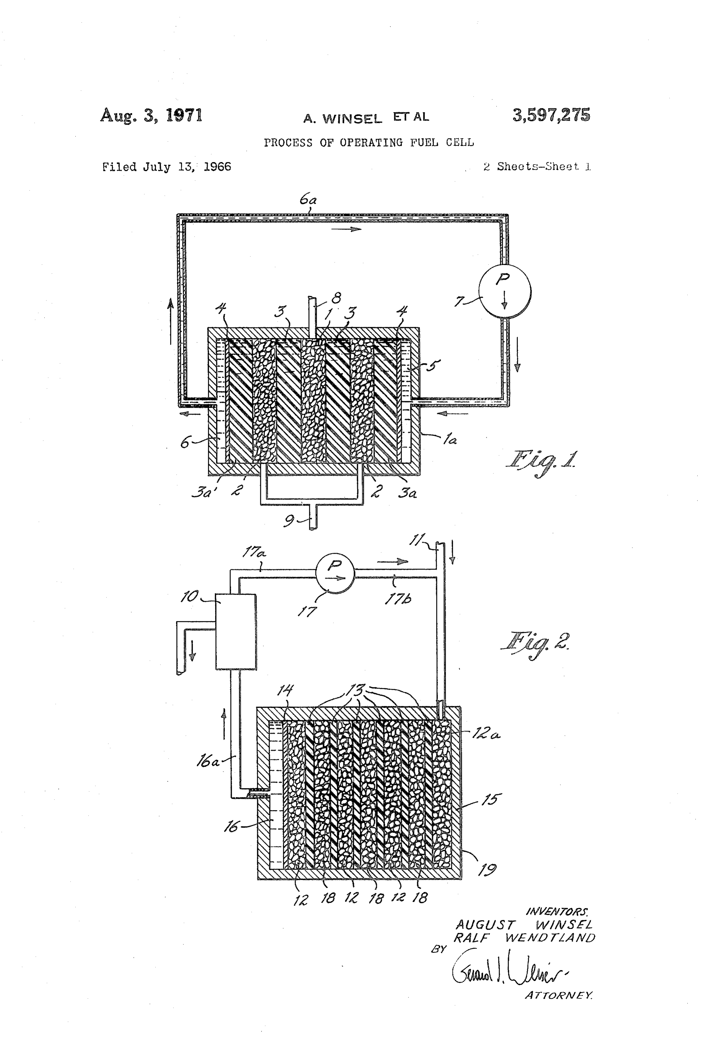
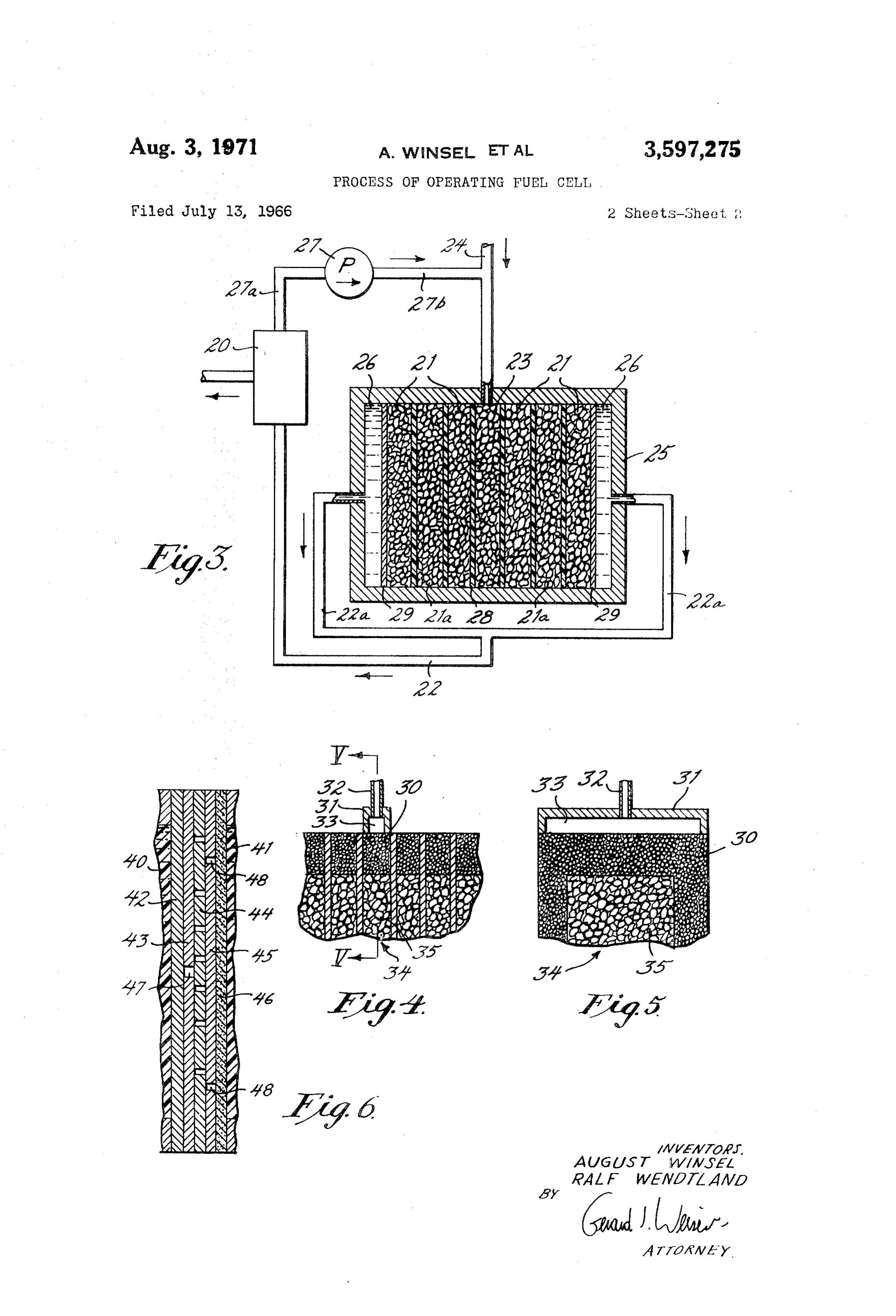
FIG. 1 is a schematic representation of a fuel cell in 60 electrolyteatand ferential which the electrodes would be flooded with at a minimum exceed the pressure created accordance with the present invention. by the increase in volumn due to the water of reaction. FIG. 2 is a Schematic representation of an embodiment The flow of the electrolyte through the fuel cell or bat of the fuel cell battery of the present invention. tery may be continuous or discontinuous, e.g. pulsating. FIG. 3 is a schematic representation of another embodi Generally, a continuous flow of the electrolyte is preferred. ment of the fuel cell battery of the invention. As is apparent from the foregoing, the present inven FIGS. 4 and 5 are fragmentary, schematic representa tion concerns also a process which permits the elimina tions of an embodiment of an electrode having an inlet or tion of the concentration polarization by the rinsing of outlet and porous edge portions for the introduction or re moval of the electrolyte at the edges of the electrode, FIG. the pores of the alternating electrodes and diaphragms 5 being a vertical section taken along line V V of FIG. 4. O contained in a battery with liquid electrolyte. This can be FIG. 6 is a Schematic, fragmentary view in section of a achieved in various ways, e.g. by the introduction or re Separatory disc with the coordinated elements forming a moval of the circulating or flowing electrolyte at or from pack disposed between the electrodes of adjacent fuel cells the edges of one or more of the dividing porous elements in a battery. of a fuel cell or battery, i.e. at or from the electrodes In the operation of the fuel cell of the present inven 75 Or the diaphragms.
Page 5
S 6
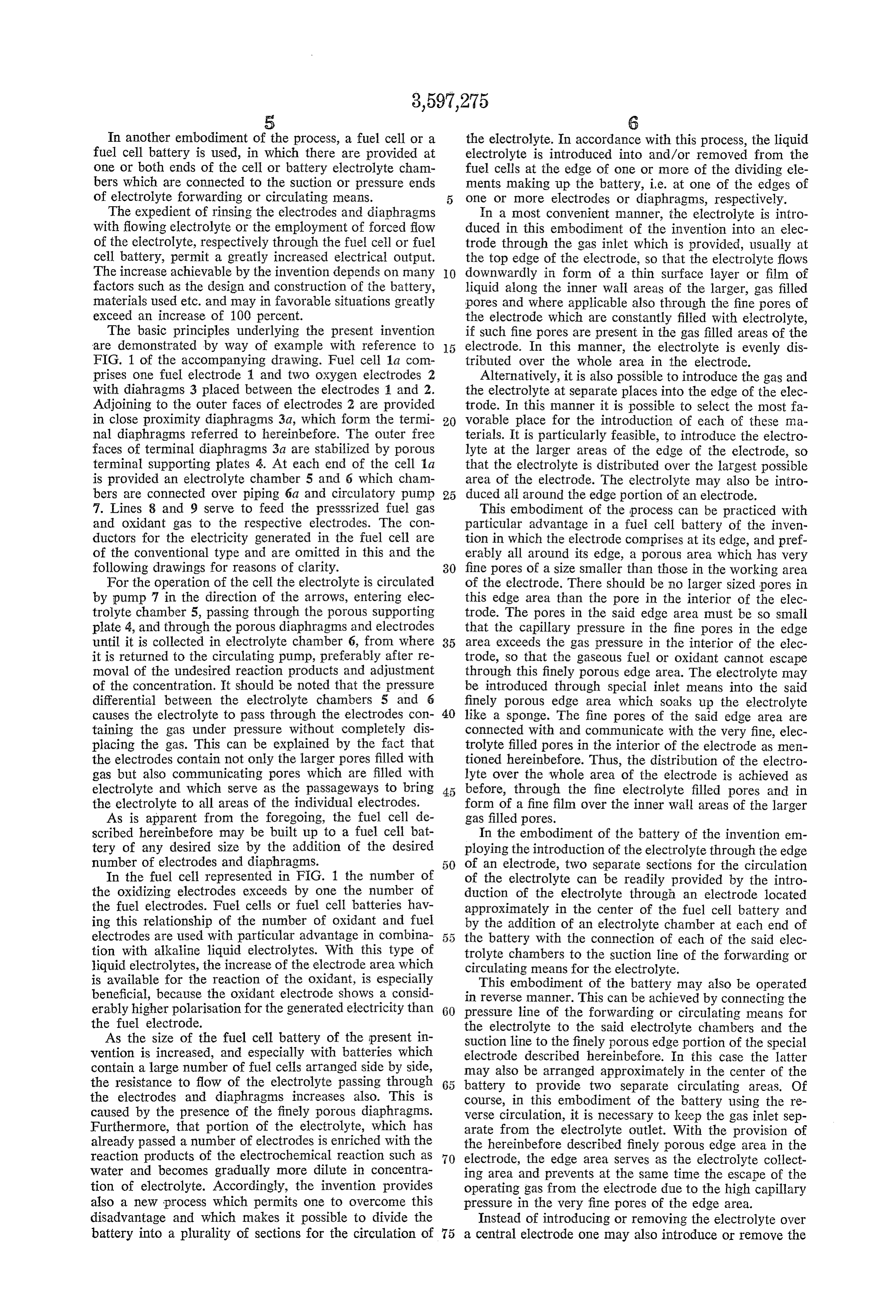
In another embodiment of the process, a fuel cell or a the electrolyte. In accordance with this process, the liquid fuel cell battery is used, in which there are provided at electrolyte is introduced into and/or removed from the one or both ends of the cell or battery electrolyte cham fuel cells at the edge of one or more of the dividing ele bers which are connected to the suction or pressure ends ments making up the battery, i.e. at one of the edges of of electrolyte forwarding or circulating means. one or more electrodes or diaphragms, respectively. The expedient of rinsing the electrodes and diaphragms In a most convenient manner, the electrolyte is intro with flowing electrolyte or the employment of forced flow duced in this embodiment of the invention into an elec of the electrolyte, respectively through the fuel cell or fuel trode through the gas inlet which is provided, usually at cell battery, permit a greatly increased electrical output.the top edge of the electrode, so that the electrolyte flows The increase achievable by the invention depends on many O downwardly in form of a thin surface layer or film of factors such as the design and construction of the battery,liquid along the inner wall areas of the larger, gas filled materials used etc. and may in favorable situations greatlypores and where applicable also through the fine pores of exceed an increase of 100 percent. the electrode which are constantly filled with electrolyte, The basic principles underlying the present invention if such fine pores are present in the gas filled areas of the are demonstrated by way of example with reference to electrode. In this manner, the electrolyte is evenly dis FIG. 1 of the accompanying drawing. Fuel cell 1a com tributed over the whole area in the electrode. prises one fuel electrode 1 and two oxygen electrodes 2 Alternatively, it is also possible to introduce the gas and with diahragms 3 placed between the electrodes 1 and 2. the electrolyte at separate places into the edge of the elec Adjoining to the outer faces of electrodes 2 are provided trode. In this manner it is possible to select the most fa in close proximity diaphragms 3a, which form the termi 20 vorable place for the introduction of each of these ma nal diaphragms referred to hereinbefore. The outer free terials. It is particularly feasible, to introduce the electro faces of terminal diaphragms 3a are stabilized by porous lyte at the larger areas of the edge of the electrode, so terminal supporting plates 4. At each end of the cell a that the electrolyte is distributed over the largest possible is provided an electrolyte chamber 5 and 6 which cham area of the electrode. The electrolyte may also be intro bers are connected over piping 6a and circulatory pump 25 duced all around the edge portion of an electrode. 7. Lines 8 and 9 serve to feed the pressSrized fuel gas This embodiment of the process can be practiced with and oxidant gas to the respective electrodes. The con particular advantage in a fuel cell battery of the inven ductors for the electricity generated in the fuel cell are tion in which the electrode comprises at its edge, and pref of the conventional type and are omitted in this and the erably all around its edge, a porous area which has very following drawings for reasons of clarity. 30 fine pores of a size smaller than those in the working area For the operation of the cell the electrolyte is circulated of the electrode. There should be no larger sized pores in by pump 7 in the direction of the arrows, entering elec this edge area than the pore in the interior of the elec trolyte chamber 5, passing through the porous Supporting trode. The pores in the said edge area must be so small plate 4, and through the porous diaphragms and electrodes that the capillary pressure in the fine pores in the edge until it is collected in electrolyte chamber 6, from where 35 area exceeds the gas pressure in the interior of the elec it is returned to the circulating pump, preferably after re trode, so that the gaseous fuel or oxidant cannot escape moval of the undesired reaction products and adjustment through this finely porous edge area. The electrolyte may of the concentration. It should be noted that the pressure be introduced through special inlet means into the said differential between the electrolyte chambers 5 and 6 finely porous edge area which soaks up the electrolyte causes the electrolyte to pass through the electrodes con 40 like a sponge. The fine pores of the said edge area are taining the gas under pressure without completely dis connected with and communicate with the very fine, elec placing the gas. This can be explained by the fact that trolyte filled pores in the interior of the electrode as men the electrodes contain not only the larger pores filled with tioned hereinbefore. Thus, the distribution of the electro gas but also communicating pores which are filled with lyte over the whole area of the electrode is achieved as electrolyte and which serve as the passageways to bring before, through the fine electrolyte filled pores and in the electrolyte to all areas of the individual electrodes. form of a fine film over the inner wall areas of the larger As is apparent from the foregoing, the fuel cell de gas filled pores.
scribed hereinbefore may be built up to a fuel cell bat In the embodiment of the battery of the invention em tery of any desired size by the addition of the desired ploying the introduction of the electrolyte through the edge number of electrodes and diaphragms. 50 of an electrode, two separate sections for the circulation In the fuel cell represented in FIG. 1 the number of of the electrolyte can be readily provided by the intro the oxidizing electrodes exceeds by one the number of duction of the electrolyte through an electrode located the fuel electrodes. Fuel cells or fuel cell batteries hav approximately in the center of the fuel cell battery and ing this relationship of the number of oxidant and fuel by the addition of an electrolyte chamber at each end of electrodes are used with particular advantage in combina the battery with the connection of each of the said elec tion with alkaline liquid electrolytes. With this type of trolyte chambers to the suction line of the forwarding or liquid electrolytes, the increase of the electrode area which circulating means for the electrolyte. is available for the reaction of the oxidant, is especially This embodiment of the battery may also be operated beneficial, because the oxidant electrode shows a consid in reverse manner. This can be achieved by connecting the erably higher polarisation for the generated electricity than 60 pressure line of the forwarding or circulating means for the fuel electrode. the electrolyte to the said electrolyte chambers and the As the size of the fuel cell battery of the present in suction line to the finely porous edge portion of the special vention is increased, and especially with batteries which electrode described hereinbefore. In this case the latter contain a large number of fuel cells arranged side by side, may also be arranged approximately in the center of the the resistance to flow of the electrolyte passing through 65 battery to provide two separate circulating areas. Of the electrodes and diaphragms increases also. This is course, in this embodiment of the battery using the re caused by the presence of the finely porous diaphragms. verse circulation, it is necessary to keep the gas inlet sep Furthermore, that portion of the electrolyte, which has arate from the electrolyte outlet. With the provision of already passed a number of electrodes is enriched with the the hereinbefore described finely porous edge area in the reaction products of the electrochemical reaction Such as 70 electrode, the edge area serves as the electrolyte collect water and becomes gradually more dilute in concentra ing area and prevents at the same time the escape of the tion of electrolyte. Accordingly, the invention provides operating gas from the electrode due to the high capillary also a new process which permits one to overcome this pressure in the very fine pores of the edge area. disadvantage and which makes it possible to divide the Instead of introducing or removing the electrolyte over battery into a plurality of sections for the circulation of 75 a central electrode one may also introduce or remove the
Page 6
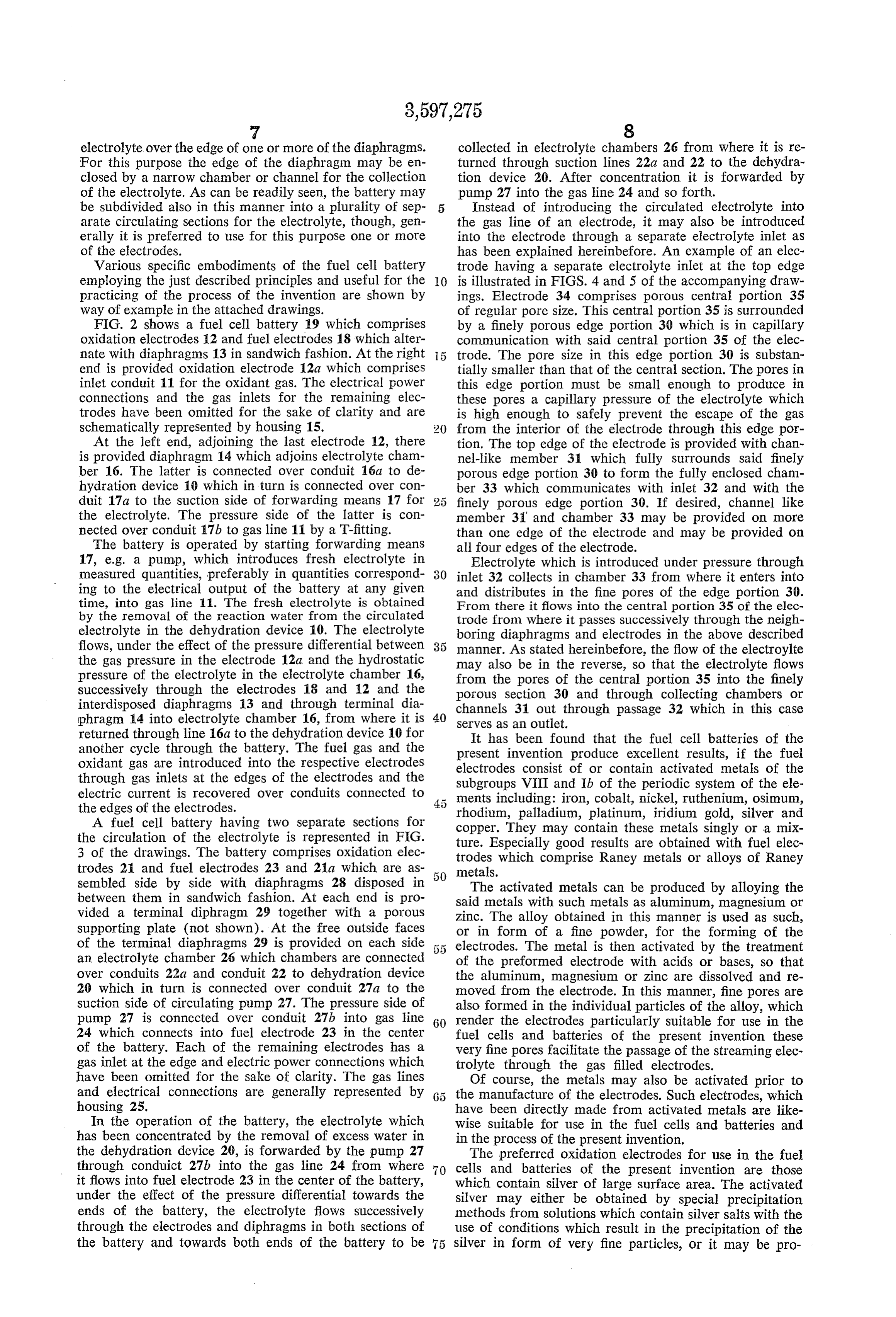
electrolyte over the edge of one or more of the diaphragms. collected in electrolyte chambers 26 from where it is re For this purpose the edge of the diaphragm may be en turned through suction lines 22a and 22 to the dehydra closed by a narrow chamber or channel for the collection tion device 20. After concentration it is forwarded by of the electrolyte. As can be readily seen, the battery may pump 27 into the gas line 24 and so forth. be subdivided also in this manner into a plurality of Sep Instead of introducing the circulated electrolyte into arate circulating sections for the electrolyte, though, gen the gas line of an electrode, it may also be introduced erally it is preferred to use for this purpose one or more into the electrode through a separate electrolyte inlet as of the electrodes. has been explained hereinbefore. An example of an elec Various specific embodiments of the fuel cell battery trode having a separate electrolyte inlet at the top edge employing the just described principles and useful for the O is illustrated in FIGS. 4 and 5 of the accompanying draw practicing of the process of the invention are shown by ings. Electrode 34 comprises porous central portion 35 way of example in the attached drawings. of regular pore size. This central portion 35 is surrounded FIG. 2 shows a fuel cell battery 19 which comprises by a finely porous edge portion 30 which is in capillary oxidation electrodes 12 and fuel electrodes 18 which alter communication with said central portion 35 of the elec nate with diaphragms 13 in sandwich fashion. At the right 5 trode. The pore size in this edge portion 30 is substan end is provided oxidation electrode 12a which comprises tially smaller than that of the central section. The pores in inlet conduit 1 for the oxidant gas. The electrical power this edge portion must be small enough to produce in connections and the gas inlets for the remaining elec these pores a capillary pressure of the electrolyte which trodes have been omitted for the sake of clarity and are is high enough to safely prevent the escape of the gas schematically represented by housing 15. from the interior of the electrode through this edge por At the left end, adjoining the last electrode 12, there tion. The top edge of the electrode is provided with chan is provided diaphragm 14 which adjoins electrolyte cham nel-like member 31 which fully surrounds said finely ber 16. The latter is connected over conduit 16a to de porous edge portion 30 to form the fully enclosed chann hydration device 10 which in turn is connected over con ber 33 which communicates with inlet 32 and With the duit 17a to the suction side of forwarding means 17 for finely porous edge portion 30. If desired, channel like the electrolyte. The pressure side of the latter is con member 3 and chamber 33 may be provided on more nected over conduit 17b to gas line 11 by a T-fitting. than one edge of the electrode and may be provided on The battery is operated by starting forwarding means all four edges of the electrode.
17, e.g. a pump, which introduces fresh electrolyte in Electrolyte which is introduced under pressure through measured quantities, preferably in quantities correspond inlet 32 collects in chamber 33 from where it enters into ing to the electrical output of the battery at any given and distributes in the fine pores of the edge portion 30. time, into gas line 11. The fresh electrolyte is obtained From there it flows into the central portion 35 of the elec by the removal of the reaction water from the circulated trode from where it passes successively through the neigh electrolyte in the dehydration device 10. The electrolyte boring diaphragms and electrodes in the above described flows, under the effect of the pressure differential between manner. As stated hereinbefore, the flow of the electroylte the gas pressure in the electrode 12a and the hydrostatic may also be in the reverse, so that the electrolyte flows pressure of the electrolyte in the electrolyte chamber 16, from the pores of the central portion 35 into the finely successively through the electrodes 18 and 12 and the porous section 30 and through collecting chambers or interdisposed diaphragms 13 and through terminal dia channels 31 out through passage 32 which in this case phragm 14 into electrolyte chamber 16, from where it is 40 Serves as an outlet.
returned through line 16a to the dehydration device 10 for It has been found that the fuel cell batteries of the another cycle through the battery. The fuel gas and the present invention produce excellent results, if the fuel oxidant gas are introduced into the respective electrodes electrodes consist of or contain activated metals of the through gas inlets at the edges of the electrodes and the Subgroups VIII and Ib of the periodic system of the ele electric current is recovered over conduits connected to ments including: iron, cobalt, nickel, ruthenium, osimum, the edges of the electrodes. rhodium, palladium, platinum, iridium gold, silver and A fuel cell battery having two separate sections for copper. They may contain these metals singly or a mix the circulation of the electrolyte is represented in FIG. ture. Especially good results are obtained with fuel elec 3 of the drawings. The battery comprises oxidation elec trodes which comprise Raney metals or alloys of Raney trodes 21 and fuel electrodes 23 and 21a which are as metals.
sembled side by side with diaphragms 28 disposed in The activated metals can be produced by alloying the between them in sandwich fashion. At each end is pro said metals with such metals as aluminum, magnesium or vided a terminal diphragm 29 together with a porous Zinc. The alloy obtained in this manner is used as such, supporting plate (not shown). At the free outside faces or in form of a fine powder, for the forming of the of the terminal diaphragms 29 is provided on each side 5 5 electrodes. The metal is then activated by the treatment an electrolyte chamber 26 which chambers are connected of the preformed electrode with acids or bases, so that over conduits 22a and conduit 22 to dehydration device the aluminum, magnesium or zinc are dissolved and re 20 which in turn is connected over conduit 27a to the moved from the electrode. In this manner, fine pores are suction side of circulating pump 27. The pressure side of also formed in the individual particles of the alloy, which pump 27 is connected over conduit 27b into gas line 60 render the electrodes particularly suitable for use in the 24 which connects into fuel electrode 23 in the center fuel cells and batteries of the present invention these of the battery. Each of the remaining electrodes has a very fine pores facilitate the passage of the streaming elec gas inlet at the edge and electric power connections which trolyte through the gas filled electrodes. have been omitted for the sake of clarity. The gas lines Of course, the metals may also be activated prior to and electrical connections are generally represented by 65 the manufacture of the electrodes. Such electrodes, which housing 25. have been directly made from activated metals are like In the operation of the battery, the electrolyte which Wise Suitable for use in the fuel cells and batteries and has been concentrated by the removal of excess water in in the process of the present invention. the dehydration device 20, is forwarded by the pump 27 The preferred oxidation electrodes for use in the fuel through conduict 27b into the gas line 24 from where cells and batteries of the present invention are those it flows into fuel electrode 23 in the center of the battery, which contain silver of large surface area. The activated under the effect of the pressure differential towards the silver may either be obtained by special precipitation ends of the battery, the electrolyte flows successively methods from solutions which contain silver salts with the through the electrodes and diphragms in both sections of use of conditions which result in the precipitation of the the battery and towards both ends of the battery to be silver in form of very fine particles, or it may be pro- -
Page 7
duced by the just described methods comprising the acti if the neighboring electrodes, separated by the said separa vation of the silver in an alloy in form of a powder or tory disc have different polarity, it is of advantage to make of a preformed electrode. Sometimes it is of advantage to the separatory disc from an electrically conductive mate add to the silver special activators. rial and preferably from a metal, so that both electrodes The hereinbefore described fuel cell batteries and fuel are directly electrically connected. Of course, to achieve cells, in which the electrodes comprise at their edges gas this there is used for the diaphragms adjoining the sepa inlets may also be operated with liquid fuels and/or ratory disc in this case also a material which is an electron oxidants instead of the gaseous reactants described here conductor. In practice this can be readily achieved by the inbefore. Furthermore, the fuel cells or batteries of the use of electrodes which have on one side a porous metallic invention may also be used, in conjunction with a source O cover layer of the requisite small pore size. Such layers of direct current, for the electrolysis of aqueous solutions. may be readily produced from a metal powder. The elec The electrolyte circulating system described hereinbefore trodes containing these cover layers on one side, are in makes the batteries of the invention particularly suitable Serted in the battery such that the metallic cover layer for this use. It is thereby possible to recover the gases faces the separatory disc.
formed in the electrolysis under pressure, because of the The principle of the separatory disc and its incorpora fact that the capillary pressure of the electrolyte in the tion in a battery is Schematically represented in FIG. 6 of pores of the diaphragms is higher than the gas pressure the accompanying drawings. It is apparent from the fore in the pores of the electrodes, as has been set out herein going that the parts used to build up the separatory disc before in detail. arrangement may be made from plastics or from metals Useful electrolytes for use in the process of the inven depending on the intended use. In the multilayer arrange tion include, for instance, 5 N to 10 N potassium hy ment there are contained in this order, the terminal dia droxide or sodium hydroxide solutions, concentrated hy phragm 40 of a fuel cell, and an adjoining layer represent drochloric or sulfuric acid solutions, and other bases and ed by collector plate 42. This plate contains passageways acids of such strength. (not shown) which are designed to collect and conduct the Several of the fuel cells of the present invention may 25 flowing electrolyte with minimum resistance to flow of also be combined to a battery in which the individual fuel electrolyte to its central area. Next follows stop plate 43 cells are operated in series. With this arrangement it is which is impermeable to the electrolyte and which has at required that the electrolyte connection between two neigh its center a hole shaped passage 47. In the center of the boring electrodes, being part of two different fuel cells, Separatory disc arrangement is a so-called labyrinthian has as high an electrical resistance as is possible, in order 30 disc 44 which contains the above described long channel to cause as little as possible interference with the rinsing or channels (not shown) which extend from the central of the electrodes with the flowing electrolyte, and in order area to the outerlying areas. The next member in the ar to permit the keeping of the forwarding pressure within ac rangement is another impermeable plate 45 with hole ceptable limits. shaped passageways 48 provided in a position opposite This can be achieved, in accordance with the present in the places of termination of the long channel or channels. vention, by flowing the streaming electrolyte from one cell The next member is a porous collector disc 46 which is to the next cell through an elongated channel, said chan followed by the terminal diaphragm 41 of the neighboring nel being so dimensioned that the resistance of the thread fuel cell.
of electrolyte contained in said channel is large compared 40 As is evident diaphragms 40 and 41 may also be re to the inner resistance of the cell, with at the same time the placed by the above described porous metallic faces of the Smallest possible resistance to flow of the electrolyte from electrodes if their use is indicated. cell to cell. For the operation of the separatory disc just described, This process can be carried out with advantage in a bat electrolyte flows from the left to right passing in a wide tery, in which are provided separatory discs between the cross section path over the whole area of diaphragm 40. It neighboring electrodes of adjoining different cells, and is then collected by the collector plate 42 and led to the wherein the separatory discs contain at least one long center where it passes through passage 47 into the long channel for the passage of the electrolyte. In order to keep winding channel of the labyrinthian disc which it leaves the size of the battery small, and to keep the electrodes at passages or passages 48 of plate 45 and from where it closely spaced, said channel for the electrolyte has pref flows into collector disc 46 which redistributes the flowing erably the form of a spiral or meander, which are incor 50 electrolyte over the whole surface area or face of the porated in said flat separatory disc. following diaphragm 41, from where it flows to the ad The best dimensions of said channel for the electrolyte, joining electrode in the next cell. i.e. its diameter "2r' and its length “1” can be readily It will be apparent that while the invention has been calculated, so that the resistance to flow of the electrolyte described for the most part with specific reference to the does not exceed the acceptable value for a given fuel cell 5 5 various embodiments of the fuel cell and fuel cell battery battery. As stated, the length "I' of the channel must be that the invention also includes the methods of operating chosen such that the resistance “R” represented by the the fuel cell and fuel cell battery, and it is believed that thread of electrolyte is substantially larger than the inner the method is apparent from the description contained resistance of each of the fuel cells of which the battery is herein.
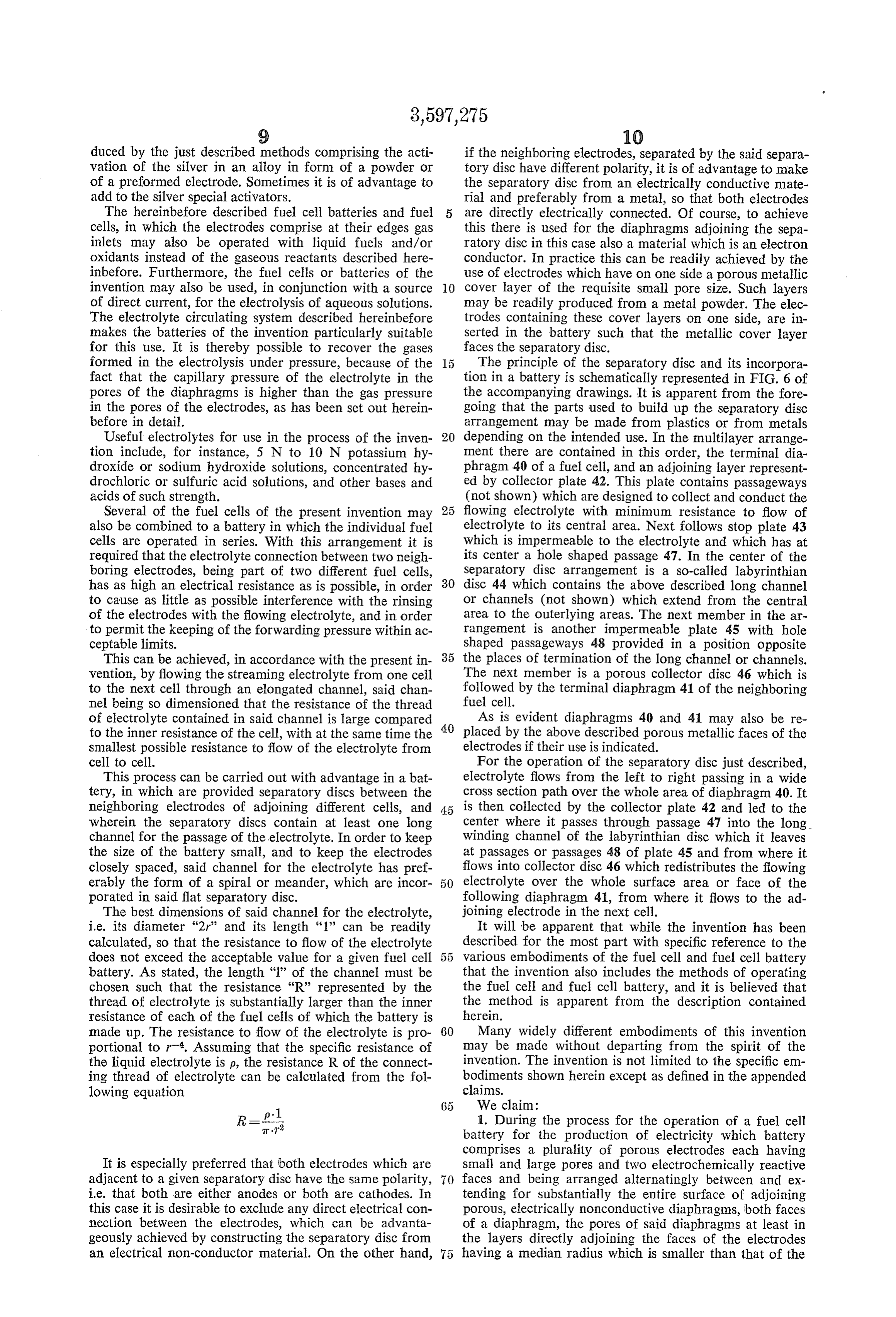
made up. The resistance to flow of the electrolyte is pro 60 Many widely different embodiments of this invention portional to r. Assuming that the specific resistance of may be made without departing from the spirit of the the liquid electrolyte is p, the resistance R of the connect invention. The invention is not limited to the specific em ing thread of electrolyte can be calculated from the fol bodiments shown herein except as defined in the appended lowing equation claims.
R=P 1. During the process for the operation of a fuel cell battery for the production of electricity which battery comprises a plurality of porous electrodes each having
It is especially preferred that both electrodes which are Small and large pores and two electrochemically reactive adjacent to a given separatory disc have the same polarity, faces and being arranged alternatingly between and ex i.e. that both are either anodes or both are cathodes. In tending for Substantially the entire surface of adjoining this case it is desirable to exclude any direct electrical con porous, electrically nonconductive diaphragms, both faces nection between the electrodes, which can be advanta of a diaphragm, the pores of said diaphragms at least in geously achieved by constructing the separatory disc from the layers directly adjoining the faces of the electrodes an electrical non-conductor material. On the other hand, having a median radius which is smaller than that of the
Page 8
pores at the faces of the electrodes, which process com 6. The process of claim in which the electrolyte exists prises passing sequentially through said electrodes and the battery through two electrolyte chambers positioned diaphragms a flow of liquid electrolyte while introducing at the opposite ends of the battery. fuel and oxidant gases into the respective electrodes. 7. The process of claim 1 wherein the electrolyte is 2. The process of claim 1 for the operation of the fuel 5 recirculated to the fuel cell battery. cell battery comprising a plurality of fuel cells in series which process comprises forwarding electrolyte from each References Cited cell to the next cell through a perforated electrolyte UNITED STATES PATENTS permeable labyrinthian disc through which the electrolyte 3,055,964 9/1962 Solomon et al. ------ 136-20X passes as a long thread, which thread has such a dimension O
that the resistance to flow of the electrolyte is selectively 3,057,943 10/1962 Strauss --------------- 136-6 low and the electrical resistance of the said thread of electrolyte is greater than the inner resistance of each 3,172,783 3/1965 Stanimirovitch -------- 136-6 of the fue cells. ?3 174,878 3/1965 PeterS ?????????----?---- ??? 136-6 3. The process of claim 1 in which the flow of the 5 265?3 534? 8/1966 RuetSchi ------------------------ 136-6 electrolyte is achieved by producing a pressure differential 3.342,639 9/1967 Harivel ------------ 136-28X between the ends of the battery and the place of intro 409,366 8/1889 Nond et al. —————————— 136-86 duction of the flowing electrolyte into the battery. 2,070,612 2/1937 Neiderreither ---------- 136-86 4. The process of claim 1 in which the flowing electro 2,175,523 10/1939 --?Greger ??? - - - - - - ? ? 136-86 lyte is introduced through a passage at the edge of at 20 3,035,998 5/1962 Sommer et al. ------ 136-86X
least one of the electrodes. 3,316,167 4/1967 Clarke, Sr. et al. -- 136-86X 5. The process of claim 1 wherein the electrolyte passes 3,369,938 2/1968 Kroeger et al. ----------- 136-86 through a terminal electrolyte chamber after passage through the terminal electrode. ALLEN B. CURTIS, Primary Examiner
Provenance
- Collection
- Cited prior art
- Original PDF
- patentimages.storage.googleapis.com →
- Filed
- 1966-07-13
- Pages
- 8
- Method
- pdftotext (the PDF's own text layer) + pdftoppm 300dpi page scans
- Source
- Google Patents bibliographic record
- Granted
- 1971-08-03
- Inventors
- August Winsel; Ralf Wendtland; VARTA AG; Siemens Corp
- Transcribed from
- patentimages.storage.googleapis.com →