patent · US4002553
Apparatus for the separation, and storage of hydrogen gas
11 January 1977
Page 1 — bibliographic record
United States Patent to 11, 4,002,553 Arntz 45 Jan. 11, 1977
54 APPARATUS FOR THE SEPARATION, AND 3,630,001 12/1971 Hamerski ............................ 55/158
STORAGE OF HYDROGEN GAS
76 Inventor: Friedrich Ottokar Wilhelm Arntz, Primary Examiner-Bernard Nozick Rte. No. 1 Summit Grove, Clinton,
Ind. 47842 57 ABSTRACT (22 Filed: Mar. 4, 1976 This invention pertains to a new type of method and Appl. No.: 663,783 apparatus for separating, accumulating, compressing 21 and subsequently storing hydrogen gas in a gas column Related U.S. Application Data separator system, whereby the lighter and lower density gas hydrogen may be pumped from the top of the col 63 Continuation-in-part of Ser. No. 586,648, June 13, umn and the change in gas difference, when the higher 1975, abandoned. density and heavier gas appears is sensed thus, auto (52) U.S. Cl. ................................. 204/278; 23/260; matically stopping the hydrogen gas compressor pump 55/17; 55/18; 55/158; 5512 12:55/DIG. 30; motor unit until the hydrogen gas in the top gas cells is 204/275 replenished and sensing units probing such hydrogen 51 Int. Cl.’....................... C25B 1/02; C25B 1/04 content subsequently instruct aforementioned hydro (58 Field of Search ................ 55/17, 18, 158, 212, gen compressor pump motor unit to resume pumping, 55/DIG. 30; 204/275,278; 23/260 such functions being in interaction with the operation 56) References Cited of a hydrolizer unit, water supply pump, storage unit, and power supply means.
UNITED STATES PATENTS
1380, 183 5/1921 Bolsen ............................... 2041278 2,958,391 l/1960 DeRosset ................... ' 4 0 . 8 w w w w 55/58 10 Claims, 1 Drawing Figure
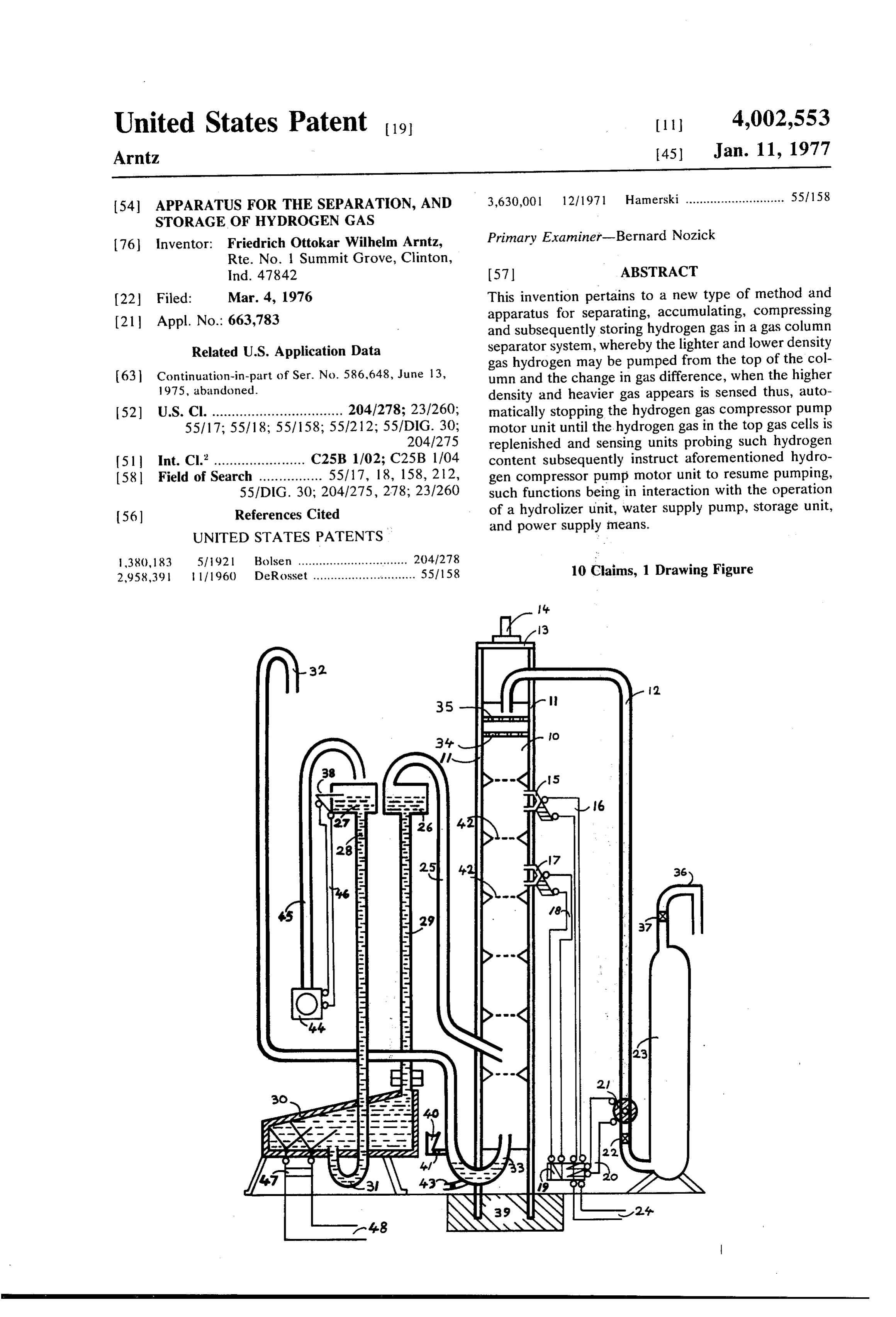
Page 2
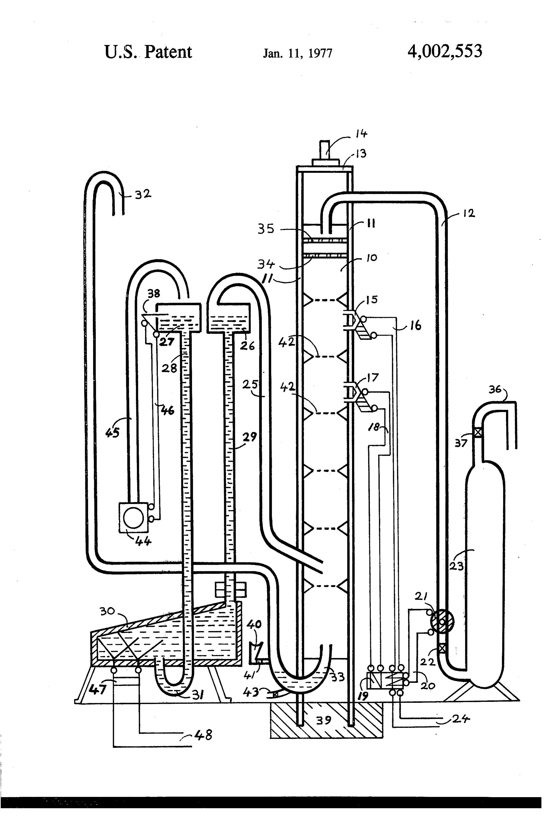
Drawing sheet — no readable text.
Page 3
probe units 15 and 17. 22 is a check valve set between
APPARATUS FOR THE SEPARATION, AND compressor unit 21 and hydrogen storage tank 23.36 is STORAGE OF HYDROGEN GAS a ventline equipped with pressure relief valve 37. 15 This application is a continuation-in-part of Ser. No. and 17 are connected to electric control box 19 by 586,648 filed June 13, 1975 and now abandoned. 5 control connections 16 and 18. 24 and 20 are supply
BACKGROUND OF THE INVENTION
current leads for compressor unit 21.33 is a waste gas exhaust line portion shaped like a U-tube which is af 1. Field of the Invention fixed with filler pipe 40 and shut off valve 41, and also The invention relates to the production and storage drain valve 43. Line 32 is the remainder of the waste of hydrogen, and more particularly to a method and 10 gas exhaust line connecting into 33. The bottom sec apparatus for separating, accumulating, compressing tion of U-tube 33 contains a volume of water for the and storing hydrogen gas with a minimum amount of purpose of acting as a flame retarder and to take on the attendance. function of a liquid check valve.33 originates from a 2. Description of the Prior Art point at the bottommost segment of cell column 10 Present methods of separating hydrogen are by vari 5 connecting into the remaining exhaustline segment 32 ous chemical processes or by pressure differential and the eventual exhaust orifice of which ends at an eleva filtering processes. - tion equal or close to the top elevation of hydrogen SUMMARY OF THE INVENTION suction line 12.25 is a gas mix feed line leading from the gas mix bubble chamber 26 and discharging into
It is an object of this invention to provide a method the gas cell column at an elevation near it's bottom and apparatus for separating, accumulating, compress segment. 29 is the gas mix bubble chamber column line ing and storing hydrogen gas whereby this may be done connecting to hydrolizer unit 30. 27 is filler tank for automatically and reliably. These and other objects are water feed column line 28.31 is the U-shaped segment preferably accomplished by filling a vertical gas con of water feed column line 28 connecting into the hy tainer column with a mixture of gases containing 25 drolizer unit 30 at it's bottom. 38 is water level sensor among others hydrogen gas, wherein aforesaid vertical unit attached to filler tank 27. 44 is watersupply pump gas container column consists of a number of gas con for 27 shown with pipe connection 45. 46 are sensor tainer cells interconnected to each other, each cell unit control connections to 44. 47 is hydrolizer feed separation membrane having one or more orifices al current interruptor unit. 48 are feed current leads for lowing a free flow gas movement up and down within 30 hydrolizer unit" 30. In operation the apparatus and the column, further wherein by having to pass through method herein described functions as follows: Hydrol the separator cell membrane orifices such flow of gas izer unit 30 fractures water contained in this unit into taking place very slowly and consequently diminishing hydrogen, oxygen and other gases. This gas mix auto any developing gas turbulence within the gas cell col matically rises upwards into the gas mix bubble cham umn, and further wherein the lower density and lighter 35 ber 26 through bubblechamber column line 29. From gas hydrogen may be pumped from the column and the chamber 26 this gas mix by being slightly pressurized change in gas layer content, when the higher density continues into gas cell column 10 and enters it at an heavier gas appears is sensed thus, automatically stop elevation somewhere near the bottom segment of col ping the pumping out and subsequent compression of umn 10. The gas column 10 now is being filled with gases. This is being done in a manner which allows for 40 aforesaid gas mix. Since hydrogen is lighter than any a definite wide safety margin by using two or more other gases it tends to collect and concentrate in the probes or sensing units. top part of said gas cell column. Since during this pro BRIEF DESCRIPTION OF THE DRAWING. cess the gas cell column is absolutely airtight against the outside atmosphere the herein as wastegas consid
The drawing is a vertical sectional, partly-schematic 45 ered gases oxygen, nitrogen et al now concentrated at view of preferred apparatus for carrying out the tech the bottom part of the gas cell columni are slowly exit niques of my invention. ing out of 10 through the water lock or check con DESCRIPTION OF THE PREFERRED tained in 33. When the hydrogen gas concentration
EMBODEMENT
becomes strong enough to displace all remnants of - 50 oxygen contained in the gas cell which sensor probe
Referring to the drawing a gas cell column tower 10 unit 17 is inserted into and said sensor probe then trig is shown, which is held in a vertical position by being gers a switching mechanism that in turn switches cur anchored vertically in a concrete base 39 at ground rent to motor compressor unit 21 the concentrated elevation. Gas cell column tower 10 is affixed with hydrogen gas in the upper cell or cells of 10 is subse reinforcing structural members 11 and is affixed at it's 55 quently pumped out through suction line 12. When the top end with a means 13 to provide a base for a vertical hydrogen content concentration within the gas cell bearing shaft 14 which may be used to attach a wind which sensor probe 15 is inserted into reaches a level of turbine device to tower 10. Tower 10 contains numer dilution with oxygen sensor probe 15 will then, trigger ous cells one placed on top of the other which thusly the switch mechanism in control box 19 to interrupt the put together represent a hollow, airtight container posi 60 feed current to motor compressor pump 21 until such tioned vertically and subdivided into numerous cells. time that sensor probe 17 again senses the concentra Each cell is in gaseous communication with the adjoin tion of hydrogen content in it's gas cell to be totally ing cell by a number of orifices each cell separation devoid of oxygen and therefore starting another pump membrane 42 is equipped with. 35 and 34 are gas tur sing cycle as described before. It goes without saying bulence dissipation membranes placed underneath 65 that there may be sensors attached to this system for hydrogen suction line 12. 21 is a motor compressor other functions such as for instance a sensor that trig pump which is activated periodically and sequentially gers a complete shutdown of the whole apparatus after subject to sensing reaction of oxygen content sensing storage tank 23 is filled completely at a predetermined
Page 4
pressure setting. The purpose for unit 47 is to, by inter upper segment of the gas cell container column, rupting the feed current to hydrolizer cell 30 periodi which gas, cell is located at an elevation below the cally, allow the gas bubbles attendant to the electrolysis elevation of yet another gas cell of said gas cell process to overcome tendency of the cathode respec container column, which said other gas cell has tively anode part of unit 30 to overly attract such bub inserted into it the second and upper oxygen con bles by the ionization effect, therefore allowing the gas tent sensor probe: relais unit; bubbles to rise more freely into bubble chamber 26. and a preprogrammed arrangement of functions Also it should be self evident how sensing unit 38 would wherein the first or lower oxygen content sensor trigger water supply pump 44 when the water level in probe relais, unit upon finding no traces of oxygen tank 27 is below the predetermined elevation. 40 and O within the gas cell it is inserted into sends a signal 41 of course are for refilling knee segment 33 when it to the electric control means which effects the becomes necessary, which function could also be made switching on of supply current to the motor com automatic. 34 and 35 are the gas turbulence dissipation pressor pump and wherein the second or upper membranes which are there for the purpose of pumping oxygen content sensor probe relais unit upon sub the hydrogen gas in a complete layer rather than as a 5 sequently finding traces of oxygen within the gas turbulent and therefore diluted mass of gas. cell it is inserted into sends a signal to the electric What I claim as new and desire to secure by Letters control means which effects the switching off of the Patent of the United States of America is: supply current to the motor compressor pump 1. Apparatus for separating, accumulating, com thereby stopping the hydrogen pumping action pressing and storing hydrogen gas comprising: 20 until the hydrogen content is concentrated enough a vertical, airtight gas cell container column wherein again to repeat the pumping cycle of the compres the individual gas cell containers are stacked one sor, further wherein upon sensing a complete ab on top of the other, each gas cell being in gaseous sence of oxygen in it's gas cell after the hydrogen in communication with the adjoining cell; - the upper gas cell containers has been replenished a means to keep said gas cells separated from each 25 the first or lower oxygen content sensor probe other yet in gaseous communication; relais unit sends a corresponding signal again to the a structural means to keep said gas cell container electric control signal conductors thereby switch column in a stable vertical position; ing on supply current again to the motor compres a waste gas exhaust duct exiting said gas cell con sor pump repeating aforementioned function and tainer column at an elevation at or near it's bottom 30 followed by the second or upper oxygen content said waste gas exhaust, duct within it's bottom seg sensor probe relais unit again sending a switch-off ment including a means to effect a check valve signal to the electric control signal conducting effect; means and switching mechanism upon the recur a segment at the bottom of waste gas exhaust duct at rence of oxygen dilution in it's cell. the exit point out of gas cell container column 35 2. Apparatus according to claim having a number having a U-tube configuration wherein the bottom of gas turbulence dissipation membranes placed under part of said U-shaped duct is kept filled with a neath the hydrogen outlet suction duct. volume of liquid which assumes the function of a 3. Apparatus according to claim having a U-tube check valve; shaped waste exhaust gas duct which at the U-tube a motor compressor pump connected to a hydrogen. 40 configuration is equipped with a water filler pipe stub outlet suction duct exiting at the top of aforesaid with built-in shut-off valve and having at the bottom gas cell container column aforesaid motor com most part of said U-tube-shaped gas exhaust duct a pressor pump pumping hydrogen gas periodically drain valve inserted into it.
into a storage tank wherein a check valve is in 4. Apparatus according to claim 1 having a hydrol serted into the duct connection between motor 45 izer unit being equipped with a feed water conducting compressor pump and the storage tank; line feeding water into said hydrolizer at it's bottom in a gas mixture input feed duct discharging into the gas such a manner that the inlet segment of aforemen cell container column at an elevation near the tioned feed water conducting line is U-shaped the bot lower segment of said gas cell container column; tom part of the U-shaped segment being substantially a means to channel electric signals in conjunction SO lower than the bottom part of the hydrolizer unit, and with electric feed current switching mechanism to wherein said feed water conducting line extends up hydrogen motor compressor which means are con wards ending in a filler tank which elevationwise is nected by control connections to two oxygen con located substantially higher than the hydrolizer unit, tent sensor probe relais units inserted into two gas aforementioned filler tank being equipped with a water cells in the uppermost segment of the gas cell con 55 level sensor having control connections to a supply tainer column and containing switching mechanism water pump said water level sensor unit being preset to for turning off respectively on supply current to the effect and maintain a predetermined water level in motor compressor pump aforesaid means to chan aforesaid filler tank, and further wherein aforesaid nel electric signals in conjunction with electric feed hydrolizer unit is also equipped with a gas mix bubble current switching mechanism, said switching mech 60 chamber column duct exiting from an upper gas collec anism turning off respectively on supply current to tion area within the hydrolizer unit and extending up the motor compressor pump depending on which wards and ending in a gas mix bubble chamber the sensing signal it receives; water level of which is identical to the waterlevel of two oxygen content sensor probe relais units inserte aforesaid feed water duct filler tank and wherein the into two gas cell containers in the uppermost seg 65 gas mix bubble chamber discharges the gas mix into a ment of the gas cell container column in such a gas mix feed duct exiting the gas mix bubble chamber manner that the first oxygen content sensor probe at it's top section, said gas mix feed duct discharging relais unit is inserted into a gas cell within the further on into the gas cell container column at an
Page 5
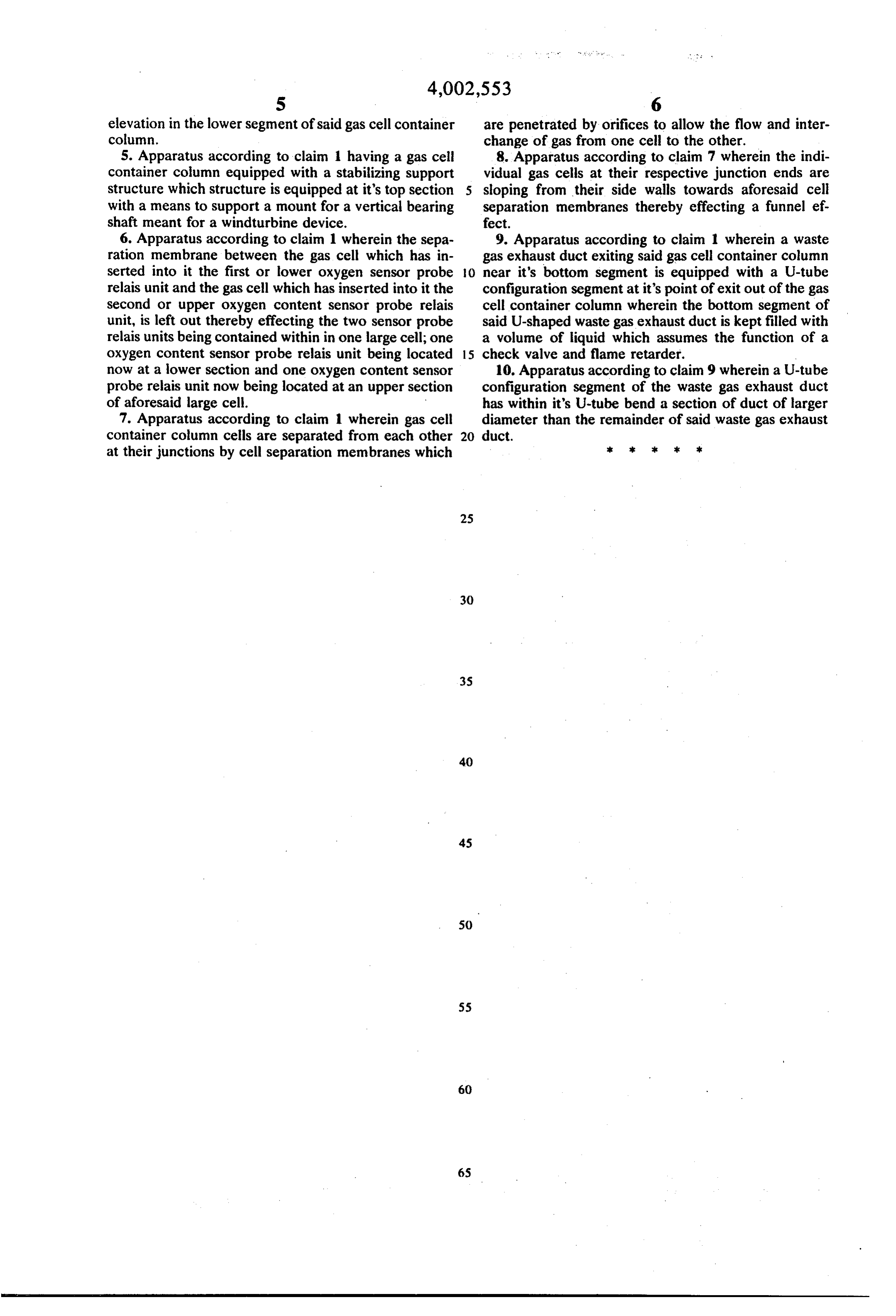
S 6 elevation in the lower segment of said gas cell container are penetrated by orifices to allow the flow and inter column. change of gas from one cell to the other. 5. Apparatus according to claim 1 having a gas cell 8. Apparatus according to claim 7 wherein the indi container column equipped with a stabilizing support vidual gas cells at their respective junction ends are structure which structure is equipped at it's top section 5 sloping from their side walls towards aforesaid cell with a means to support a mount for a vertical bearing separation membranes thereby effecting a funnel ef shaft meant for a windturbine device. fect.
6. Apparatus according to claim 1 wherein the sepa 9. Apparatus according to claim 1 wherein a waste ration membrane between the gas cell which has in gas exhaust duct exiting said gas cell container column serted into it the first or lower oxygen sensor probe O near it's bottom segment is equipped with a U-tube relais unit and the gas cell which has inserted into it the configuration segment at it's point of exit out of the gas Second or upper oxygen content sensor probe relais cell container column wherein the bottom segment of unit, is left out thereby effecting the two sensor probe said U-shaped waste gas exhaust duct is kept filled with relais units being contained within in one large cell; one a volume of liquid which assumes the function of a oxygen content sensor probe relais unit being located 15 check valve and flame retarder.
now at a lower section and one oxygen content sensor 10. Apparatus according to claim 9 wherein a U-tube probe relais unit now being located at an upper section configuration segment of the waste gas exhaust duct of aforesaid large cell. has within it's U-tube bend a section of duct of larger 7. Apparatus according to claim 1 wherein gas cell diameter than the remainder of said waste gas exhaust container column cells are separated from each other 20 duct.
at their junctions by cell separation membranes which k is
Provenance
- Collection
- Cited prior art
- Original PDF
- patentimages.storage.googleapis.com →
- Filed
- 1976-03-04
- Pages
- 5
- Method
- pdftotext (the PDF's own text layer) + pdftoppm 300dpi page scans
- Source
- Google Patents bibliographic record
- Granted
- 1977-01-11
- Inventors
- Friedrich Ottokar Wilhelm Arntz
- Transcribed from
- patentimages.storage.googleapis.com →