patent · US2494243
Pressure ribbon-type gas burner
10 January 1950
Page 1
Drawing sheet — no readable text.
Page 2
Drawing sheet — no readable text.
Page 3
Drawing sheet — no readable text.
Page 4
Patented Jan. 10, 1950 2,494,243
UNITED STATES PATENT OFFICE
PRESSURE RIBBON-TYPEGAS BURNER
Application July 31, 1944, serial No. 547,320 7 Claimi.
” : ?' ? ? ? 1 ? ". . . ?- : à . . . . . . . r . ... ???...? . . . . : ??? ?? ??. . : : " . . ? ? ?? ???
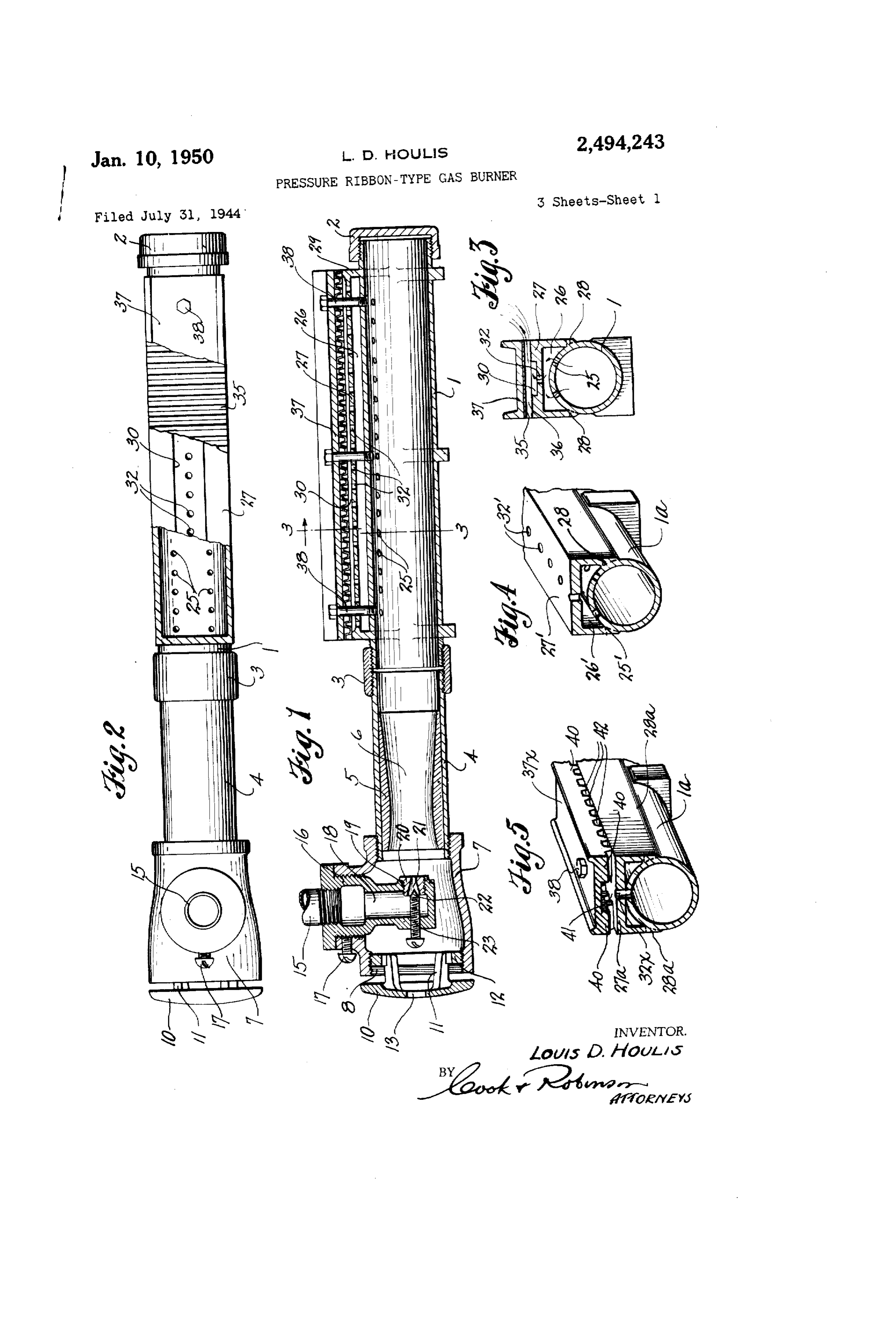
This invention relates to gas burners, and it has the inappoyed details gf construction, the preferred reference more particularly to improvements in farms qf, which are illustrated in the accompany gas burners of a type, especially adapted for in ing: drawings wherein-ri- , , , , , . . . . . . . ?
dustrial in?tallations, for, u?e in heating, and vez Fig. 1 is.a.longitudinal section of a gas burner tilating equipment, in food processing apparatus, which is typical of those embodied by this inven bakers ovens, stoyes and ranges, and in Qther 5 tion, installations where a uniform and steady flame for useshowing one form of construction suitable of air at atmospheric pressure. ,
Fig. 2 is a top, or plan view of the same burner tion to provide a gas burner of the character, 10 with parts thereof broken away for purposes of above, stated, of a simplified construction;..hat is explanation and better illustration. . . . . Fig. 3 is a cross section taken on the line 3-3, easy to install in any of its various applications;
that is readily adjustable for determination of in Fig. 1. - - - - - - -- - . " " ?"
flame character and which is easy to disassemble ... in Fig. 4 is a detail showing, in cross section and to facilitate cleaning, repair or overhaul of its 15 tive form. . a. burner. of a. simplified perspective,
alterna
. It is also, an object.of this inyention to provide Fig. 5 is a similar cross-sectional view of a a gas burner having the advantages above stated. tion. ???er of another alternative form of construc that will burn with a uniform, ribbig-like flage. :??? » - ?* ? -- ??"? ? 0 & . . ... :. . , ?' :? : "" : ,"" ??? ??? . ? ??? ??. : ???
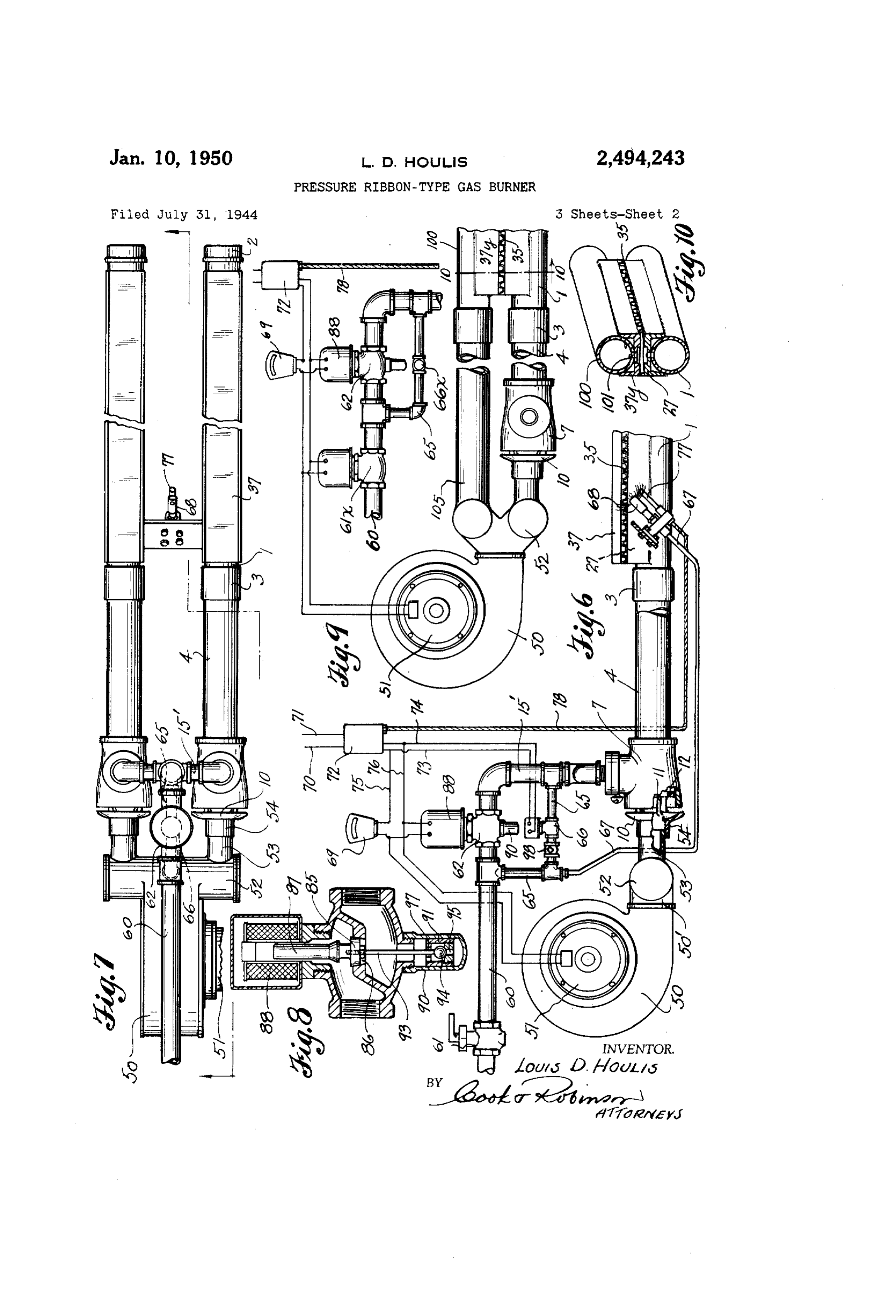
and which, by reason of its arrangement of parts Fig.6 is side view of abner present type that is equipped to use primary typical of the a and their details of, construction, has great toler either at atmospheric pressure or under forced ance of turn-dawn without, causing. backfiring. pressure. . V ?????%
and has great tolerance of primary air. and flame, Fig. 7 is a top view of the burner shown in increase without causing the flame to lift or to blow out. . . . . . . . . . . . . . . . . . . . . . . . . . .
Another, object of this, invention is to provide. 'Fig. 8 is an enlarged, cross-sectional view of a gas burner that is suitable for use of primary. the delayed action gas control valve used in the air at atmospheric pressure and which can be. pressure system of Fig. 6,
Fig. 9 is a burner arrangement equipped with successfully combined with a blower to furnish. means for supplying it with primary and second both primary and secondary air under preSSure: 30 and thereby adapted for use in normally, closed, ary air under pressure. . .. . . . . . .
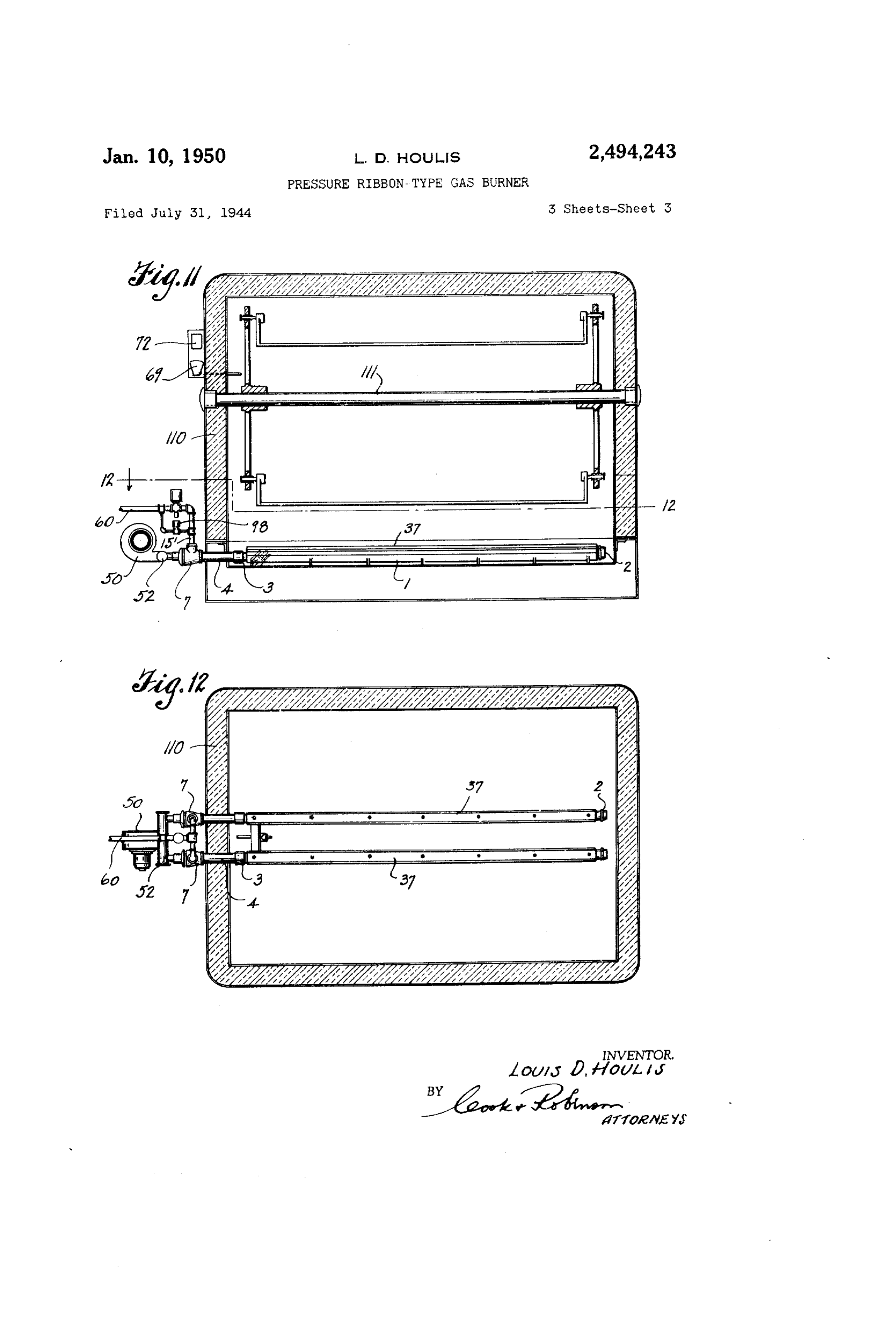
places not equipped for admission of Secondary Fig. 10 is across-sectional view and perspective 1. ? ‘ ?????? ??? "???? ?? ??? ??? . ????? . -- ** ** on the line? ?o in Fig. 9. ‘. . . . , it : Yet another object of the invention is tó-pro vide a gas burner, of the atmospheric, . . Veraturi ??:’ which burier embodying improvements of' . the type that, without structural changes or modifica.-. piresentiyerition i? instalied, ( ? ' t?› Fig. 12 is a horizontal section, taken on the line ions, gan be combined with means for supplying air under pressure, and thus converted to a pres f2-2 in Fig. 11. SS S S SqJSAASS SS SSSSSSJSSS KSS S S SSS S sure air or pressure air, and gas burner... . . . . ..., Referring more in detail to the drawings More specifically stated, the objects of this...inr. Ás was previously stated, the present burneris, vention, reside in the provision of a gas burner adaptable to various uses and the novel features. or both high and low burning flame; that can use. of construction may be embodied in such burners air at atmospheric, pressure when a minimum, or of different detail. For example, the burner may, ow, burning flame is required and Aor, as a pre be desighed for using primary air supplied thereto nixed, or induced air pressure burner, when max 45 at atmospheric pressure, or primary air under.
mum or high flame is required...Furthermore, to. pressure, or it may be designed to receive addi provide such a burner with novel means for its tional primary and secondary air under forced, automatic control,
Still further objects of the invention reside in ? ... , .. . . . . .. . . . ... :- delivery as supplied by a blower. Furthermore, he details of construction, and combination of 50 automatio control means. In the following speci.
the burner might be operated under control of parts as employed in the burner in the various fication, I will first describe the burner in a form modifications ther?gof and either as an atmos heric air or as a pressure burner. . . . . .
of... construction utilizing primary air supplied.
In accomplishing the , above mentioned and. 4, later describe the burner as equipped for the use under control at atmospheric pressure, and will ther objects of the invention, I have provided 55 of atmospheric air for low burning flame and air
Page 5
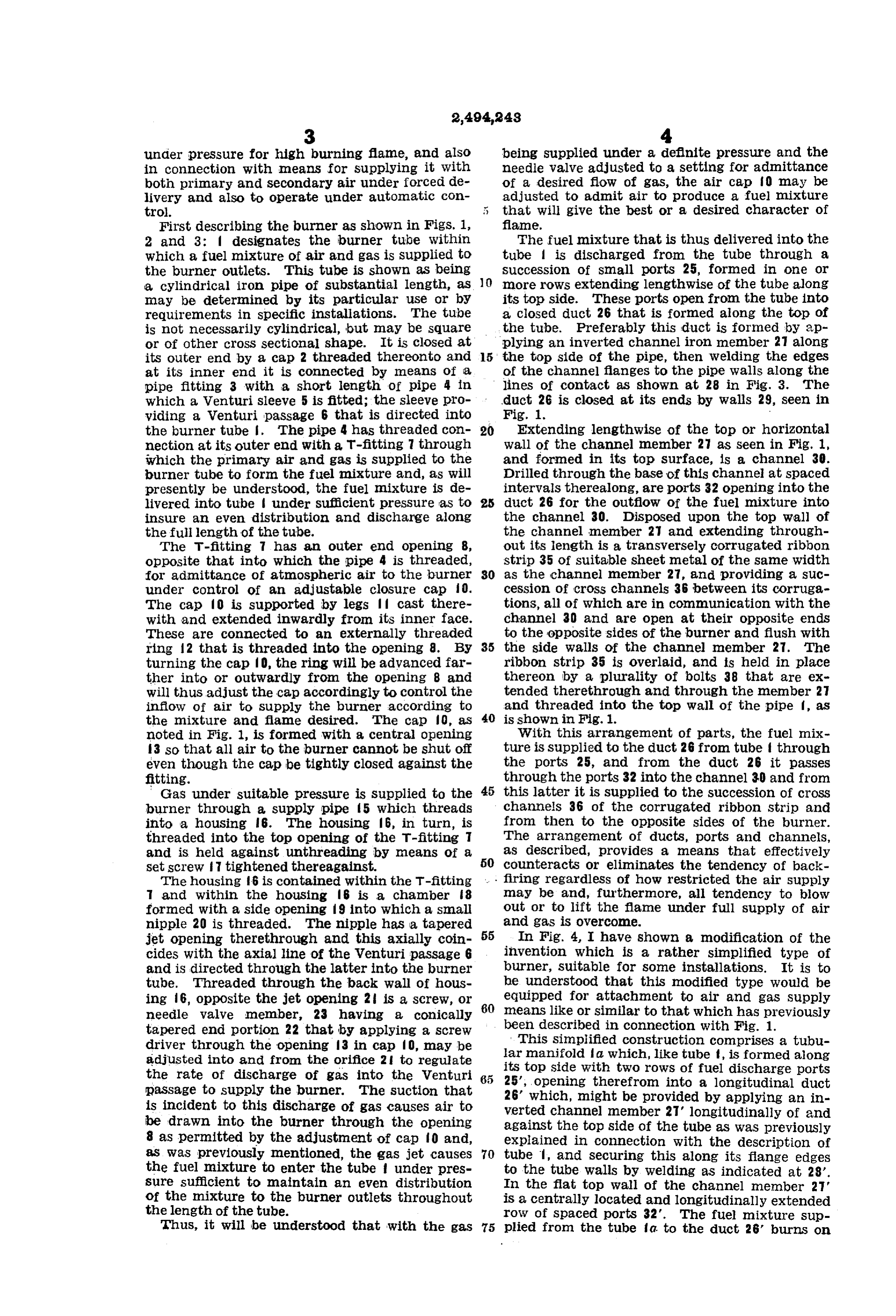
under pressure for high burning flame, and also being supplied under a definite pressure and the in connection with means for supplying it with needle valve adjusted to a setting for admittance both primary and secondary air under forced de of a desired flow of gas, the air cap ?o may be livery and also to operate under automatic con adjusted to admit air to produce a fuel mixture trol. that will give the best or a desired character of First describing the burner as shown in FigS. 1, flame.
2 and 3: designates the burner tube within Ihe fuel mixture that is thus delivered into the which a fuel mixture of air and gas is supplied to tube is discharged from the tube through a the burner outlets. This tube is shown as being succession of small ports 25, formed in one or a cylindrical iron pipe of substantial length, as O more rows extending lengthwise of the tube along may be determined by its particular use or by its top side. These ports open from the tube into requirements in specific installations. The tube a closed duct 26 that is formed along the top of is not necessarily cylindrical, but may be square the tube. Preferably this duct is formed by ap or of other cross sectional shape. It is closed at plying an inverted channel iron member 27 along its outer end by a cap 2 threaded thereonto and 5 the top side of the pipe, then welding the edges at its inner end it is connected by means of a of the channel flanges to the pipe walls along the pipe fitting 3 with a short length of pipe 4 in lines of contact as shown at 28 in Fig. 3. The duct 26 is closed at its ends by walls 29, seen in which a Wenturi sleeve 5 is fitted; the sleeve pro viding a Wenturi passage 6 that is directed into Fig. 1.
the burner tube . The pipe 4 has threaded con 20 Extending lengthwise of the top or horizontal nection at its outer end with a T-fitting 7 through wall of the channel member 27 as seen in Fig. 1, which the primary air and gas is supplied to the and formed in its top surface, is a channel 30. burner tube to form the fuel mixture and, as will Drilled through the base of this channel at spaced presently be understood, the fuel mixture is de intervals therealong, are ports 32 opening into the livered into tube under sufficient pressure as to duct 26 for the outflow of the fuel mixture into insure an even distribution and discharge along the channel 30. Disposed upon the top wall of the full length of the tube. the channel member 27 and extending through The T-fitting 7 has an outer end opening 8, out its length is a transversely corrugated ribbon opposite that into which the pipe 4 is threaded, strip 35 of suitable sheet metal of the same width for admittance of atmospheric air to the burner 30 as the channel member 27, and providing a suc under control of an adjustable closure cap 0. cession of cross channels 36 between its corruga The cap to is supported by legs if cast there tions, all of which are in communication with the with and extended inwardly from its inner face. channel 30 and are open at their opposite ends These are connected to an externally threaded to the opposite sides of the burner and flush with ring 12 that is threaded into the opening 8. By 35 the side walls of the channel member 27. The turning the cap 0, the ring will be advanced far ribbon strip 35 is overlaid, and is held in place ther into or outwardly from the opening 8 and thereon by a plurality of bolts 38 that are ex will thus adjust the cap accordingly to control the tended therethrough and through the member 27 inflow of air to supply the burner according to and threaded into the top wall of the pipe f, as the mixture and flame desired. The cap 0, as 40 is shown in Fig. 1.
noted in Fig. 1, is formed with a central opening With this arrangement of parts, the fuel mix 3 so that all air to the burner cannot be shut off ture is supplied to the duct 26 from tube through even though the cap be tightly closed against the the ports 25, and from the duct 26 it passes fitting. through the ports 32 into the channel 30 and from Gas under suitable pressure is supplied to the 45 this latter it is supplied to the succession of cross burner through a supply pipe 5 which threads channels 36 of the corrugated ribbon strip and into a housing 6. The housing 16, in turn, is from then to the opposite sides of the burner. threaded into the top opening of the T-fitting T The arrangement of ducts, ports and channels, and is held against unthreading by means of a as described, provides a means that effectively 50 counteracts or eliminates the tendency of back set screw tightened thereagainst.
The housing 6 is contained within the T-fitting firing regardless of how restricted the air supply and within the housing 6 is a chamber 8 may be and, furthermore, all tendency to blow formed with a side opening 9 into which a small out or to lift the flame under full supply of air nipple 20 is threaded. The nipple has a tapered and gas is Overcome.
jet opening therethrough and this axially coin 55 In Fig. 4, I have shown a modification of the cides with the axial line of the Wenturi passage 6 invention which is a rather simplified type of and is directed through the latter into the burner burner, Suitable for some installations. It is to tube. Threaded through the back wall of hous he understood that this modified type would be ing 6, opposite the jet opening 2 is a screw, or 60 equipped for attachment to air and gas supply needle Valve member, 23 having a conically means like or similar to that which has previously tapered end portion 22 that by applying a screw been described in connection with Fig. 1. driver through the opening 13 in cap fo, may be This Simplified construction comprises a tubu adjusted into and from the orifice 2 to regulate lar manifold a which, like tube f, is formed along the rate of discharge of gas into the Venturi 65 its top side with two rows of fuel discharge ports 25, opening therefrom into a longitudinal duct passage to supply the burner. The suction that 26' which, might be provided by applying an in is incident to this discharge of gas causes air to be drawn into the burner through the opening againstchannel verted the top member 2T longitudinally of and side of the tube as was previously 8 as permitted by the adjustment of cap to and, explained in connection with the description of BS was previously mentioned, the gas jet causes 70 tube , and securing this along its flange edges the fuel mixture to enter the tube under pres to the tube walls by welding as indicated at 28'. Sure sufficient to maintain an even distribution In the flat top wall of the channel member 27' of the mixture to the burner outlets throughout is a centrally located and longitudinally extended the length of the tube. row of Spaced ports 32". The fuel mixture sup Thus, it will be understood that with the gas plied from the tube a to the duct 26’ burns on
Page 6
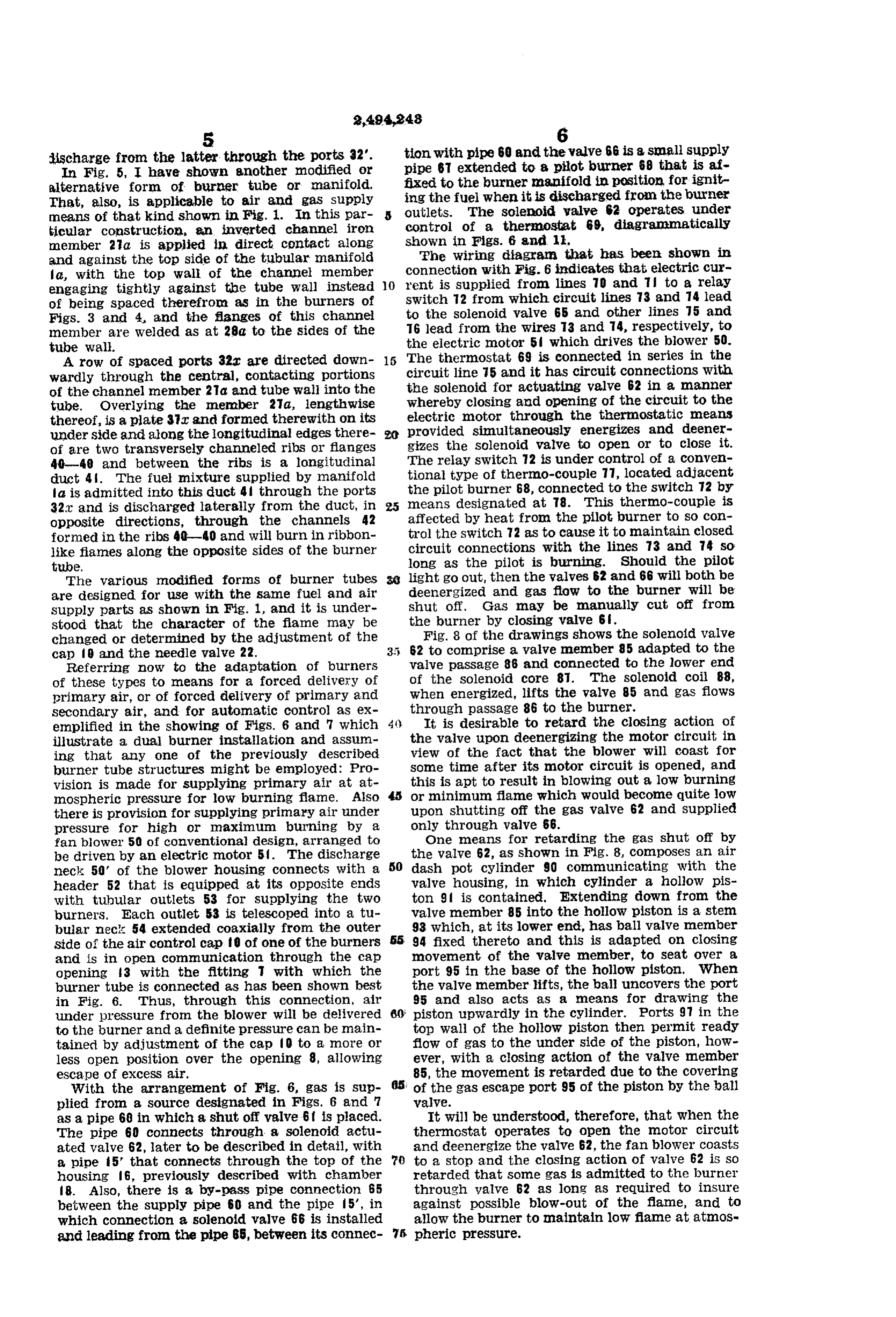
ischarge from the latter through the ports 32. tion with pipe 60 and the valve 66 is a small supply In Fig. 5, I have shown another modified or pipe 67 extended to a plot burner 68 that is af alternative form of burier tube or manifold. fixed to the burner manifold in position for ignit That, also, is applicable to air and gas supply ing the fuel when it is discharged from the burier means of that kind shown in Fig. 1. In this par outlets. The solenoid valve 62 operates under ticular construction, an inverted channel iron control of a thernostat 69, diagrammatically member 2a is applied in direct contact along shown in Figs. 6 and 11.
and against the top side of the tubular manifold The wiring diagrania that has been shown in fa, with the top wall of the channel member connection with Fig. 6 indicates that electric cur engaging tightly against the tube wall instead O rent is supplied from lines 70 and Til to a relay of being spaced therefrom as in the burners of Switch 72 from which circuit lines 73 and 74 lead Figs. 3 and 4, and the flanges of this channel to the solenoid valve 65 and other lines 75 and member are welded as at 28a to the sides of the T6 lead from the Wires 3 and 4, respectively, to tube Wal. the electric motor 5 which drives the blower 50. A row of spaced ports 32C are directed down 15 The thermostat 69 is connected in Series in the wardly through the central, contacting portions circuit line 75 and it has circuit connections with of the channel member 2d. and tube wall into the the solenoid for actuating valve 62 in a manner tube. Overlying the member 2a, lengthwise whereby closing and opening of the circuit to the thereof, is a plate 37ac and formed therewith on its electric motor through the thermostatic means under Side and along the longitudinal edges there provided simultaneously energizes and deener of are two transversely channeled ribs or flanges gizes the solenoid valve to open or to close it. 40-40 and between the ribs is a longitudinal The relay SWitch. 2 is under control of a conven duct 4. The fuel mixture supplied by manifold tional type of thermo-couple 77, located adjacent la is admitted into this duct 4 through the ports the pilot burner 68, connected to the Switch 72 by 32ac and is discharged laterally from the duct, in means designated at T8. This thermo-couple is opposite directions, through the channels 42 affected by heat from the pilot burner to so con formed in the ribs 40-40 and will burn in ribbon trol the switch 72 as to cause it to maintain closed like fiannes along the opposite sides of the burner circuit connections with the lines 73 and 74 so titube. long as the pilot is burning. Should the pilot The various modified fornias of burner tubes light go out, then the valves 62 and 66 will both be are designed for use with the same fuel and air deenergized and gas flow to the burner will be Supply parts as shown in Fig. 1, and it is under shut off. Gas may be manually cut off from stood that the character of the flame may be the burner by closing Valve 6. changed or determined by the adjustment of the Fig. 8 of the drawings shows the Solenoid valve cap 9 and the needle valve 22. 62 to comprise a valve member 85 adapted to the Referring now to the adaptation of burners valve passage 86 and connected to the lower end of these types to means for a forced delivery of of the Solenoid core 8T. The solenoid coil 88, primary air, or of forced delivery of primary and when energized, lifts the valve 85 and gas flows Secondary air, and for automatic control as ex through passage 86 to the burner. enplified in the showing of Figs. 6 and 7 which 4t). It is desirable to retard the closing action of illustrate a dual burner installation and assum the valve upon deerlergizing the motor circuit in ing that any one of the previously described view of the fact that the blower will coast for burner tube structures might be employed: Pro Some time after its motor circuit is opened, and vision is made for supplying primary air at at this is apt to result in blowing out a low burning mospheric pressure for low burning fame. Also or minimum flame which would become quite low there is provision for supplying primary air under upon shutting off the gas valve 62 and supplied pressure for high or maximum burning by a only through valve 66.
fan blower 50 of conventional design, arranged to One means for retarding the gas shut off by be driven by an electric motor 5. The discharge the valve 62, as shown in Fig. 8, composes an air neck 50 of the blower housing connects with a 50 dash pot cylinder 90 communicating with the header 52 that is equipped at its opposite ends valve housing, in which cylinder a hollow pis with tubular outlets 53 for Supplying the two tOn 9 is contained. Extending down from the burners. Each outlet 53 is telescoped into a tu Valve member 85 into the hollow piston is a stem bular neck 54 extended coaxially from the outer 93 which, at its lower end, has ball valve member Side of the air control cap 0 of one of the burners s 94 fixed thereto and this is adapted on closing and is in open communication through the cap movement of the valve member, to seat over a opening 3 with the fitting with which the port 95 in the base of the hollow piston. When burner tube is connected as has been shown best the valve member lifts, the ball uncovers the port in Fig. 6. Thus, through this connection, air 95 and also acts as a means for drawing the under pressure from the blower will be delivered 60 piston upwardly in the cylinder. Ports 97 in the to the burner and a definite pressure can be main top wall of the hollow piston then permit ready tained by adjustment of the cap 0 to a more or flow of gas to the under side of the piston, how less open position over the opening 8, allowing ever, with a closing action of the valve member escape of excess air. 85, the movement is retarded due to the covering With the arrangement of Fig. 6, gas is sup of the gas escape port 95 of the piston by the ball plied from a source designated in Figs. 6 and 7 valve.
as a pipe 68 in which a shut of valve 6 is placed. It will be understood, therefore, that when the The pipe 60 connects through a solenoid actu thermostat operates to open the motor circuit ated valve 62, later to be described in detail, with and deenergize the valve 62, the fan blower coasts a pipe 5’ that connects through the top of the 7) to a stop and the closing action of valve 62 is so housing 6, previously described with chamber retarded that some gas is admitted to the burner 8. Also, there is a by-pass pipe connection 65 through valve 62 as long as required to insure between the supply pipe 60 and the pipe 5’, in against possible blow-out of the flame, and to which connection a solenoid valve 66 is installed allow the burner to maintain low flame at atmos and leading from the pipe 65, between its connec 7. pheric pressure.
Page 7
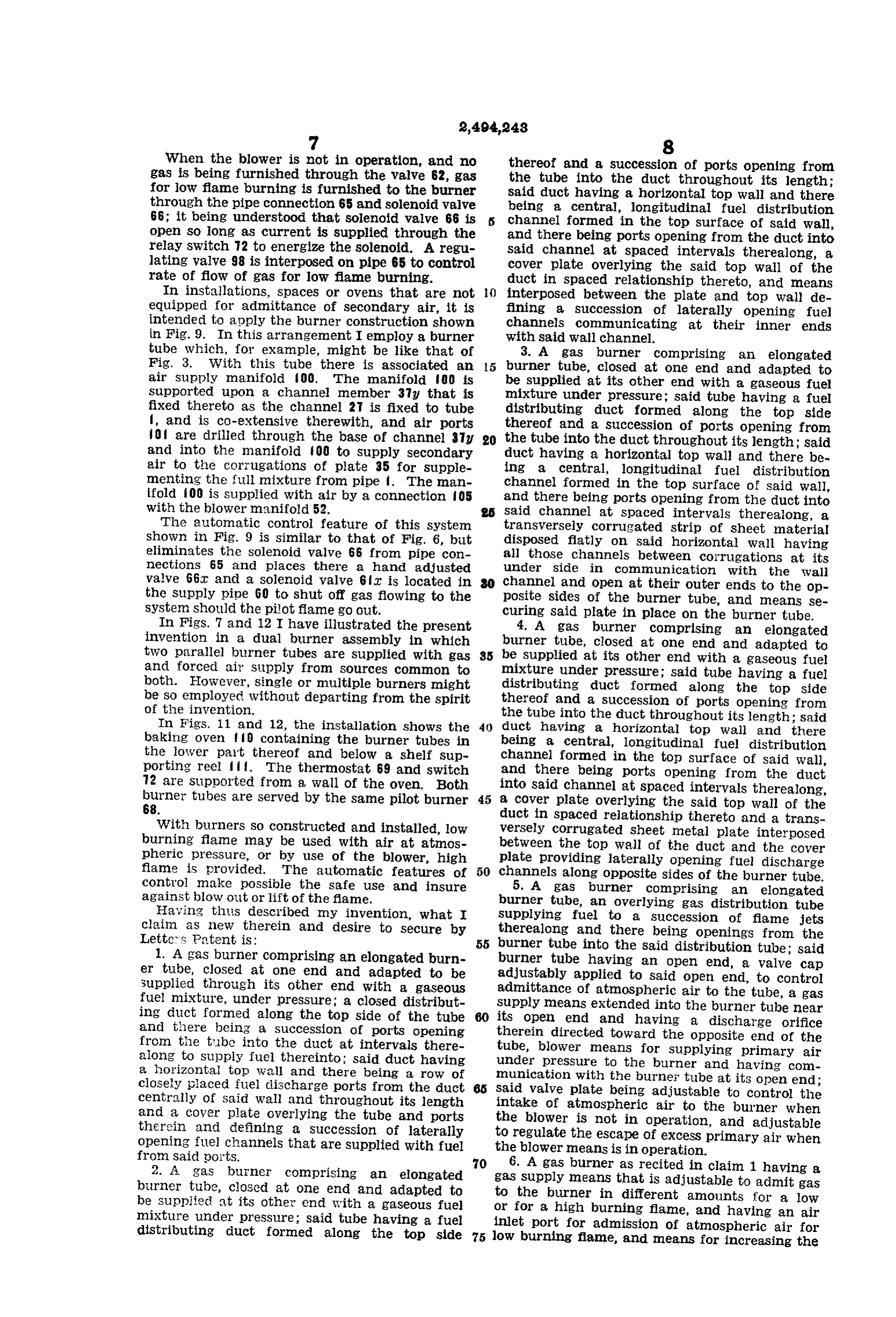
When the blower is not in operation, and no thereof and a succession of ports opening from gas is being furnished through the valve 62, gas the tube into the duct throughout its length; for low flame burning is furnished to the burner Said duct having a horizontal top wall and there through the pipe connection 65 and solenoid valve being a central, longitudinal fuel distribution 66; it being understood that solenoid valve 66 is channel formed in the top surface of said wall, open so long as current is supplied through the and there being ports opening from the duct into relay switch T2 to energize the solenoid. A regu Said channel at spaced intervals therealong, a lating valve 98 is interposed on pipe 65 to control cover plate overlying the said top wall of the rate of flow of gas for low flame burning. duct in spaced relationship thereto, and means In installations, spaces or ovens that are not () interposed between the plate and top wall de equipped for admittance of secondary air, it is fining a succession of laterally opening fuel intended to apply the burner construction shown channels communicating at their inner ends in Fig. 9. In this arrangement I employ a burner with said wall channel.
tube which, for example, might be like that of 3. A gas burner comprising an elongated Fig. 3. With this tube there is associated an 5 burner tube, closed at one end and adapted to air supply manifold 00. The manifold OO is be supplied at its other end with a gaseous fuel supported upon a channel member 3g that is mixture under pressure; said tube having a fuel fixed thereto as the channel 27 is fixed to tube distributing duct formed along the top side l, and is co-extensive therewith, and air ports thereof and a succession of ports opening from fo are drilled through the base of channel 37 y 20 the tube into the duct throughout its length; said and into the manifold 00 to supply secondary duct having a horizontal top wall and there be air to the corrugations of plate 35 for supple ing a central, longitudinal fuel distribution menting the full mixture from pipe . The man channel formed in the top surface of said wall, ifold iOO is supplied with air by a connection 05 and there being ports opening from the duct into with the blower manifold 52. said channel at spaced intervals therealong, a The automatic control feature of this system transversely corrugated strip of sheet material shown in Fig. 9 is similar to that of Fig. 6, but disposed flatly on said horizontal wall having eliminates the solenoid Valve 66 from pipe con all those channels between corrugations at its nections 65 and places there a hand adjusted under Side in communication with the wall valve 66ac and a solenoid valve 6 fac is located in channel and open at their outer ends to the op the supply pipe 60 to shut off gas flowing to the posite sides of the burner tube, and means se system should the pilot flame go out. curing said plate in place on the burner tube. In Figs. 7 and 12 I have illustrated the present 4. A gas burner comprising an elongated invention in a dual burner assembly in which burner tube, closed at one end and adapted to two parallel burner tubes are supplied with gas 35 be supplied at its other end with a gaseous fuel and forced air Supply from sources common to mixture under pressure; said tube having a fuel both. However, single or multiple burners might distributing duct formed along the top side be so employed without departing from the spirit thereof and a succession of ports opening from Of the invention. the tube into the duct throughout its length; said In Figs. 11 and 12, the installation shows the duct having a horizontal top wall and there baking oven containing the burner tubes in being a central, longitudinal fuel distribution the lower part thereof and below a shelf sup channel formed in the top surface of said wall, porting reel . The thermostat 69 and switch and there being ports opening from the duct 2 are Supported from a wall of the oven. Both into Said channel at spaced intervals therealong, burner tubes are served by the same pilot burner 45 a cover plate overlying the said top wall of the 68. duct in Spaced relationship thereto and a trans With burners so constructed and installed, low versely corrugated sheet metal plate interposed burning flane may be used with air at atmos between the top wall of the duct and the cover pheric pressure, or by use of the blower, high plate providing laterally opening fuel discharge flame is provided. The automatic features of channels along opposite sides of the burner tube. control make possible the safe use and insure 5. A gas burner comprising an elongated against blow out or lift of the flame. burner tube, an overlying gas distribution tube Having thuis described my invention, what I Supplying fuel to a succession of flame jets claim as new therein and desire to secure by therealong and there being openings from the Lette S. Pºtent is: 55 burner tube into the said distribution tube; said 1. A gas burner comprising an elongated burn burner tube having an open end, a valve cap er tube, closed at one end and adapted to be adjustably applied to said open end, to control Supplied through its other end with a gaseous admittance of atmospheric air to the tube, a gas fuel mixture, under pressure; a closed distribut Supply means extended into the burner tube near ing duct formed along the top side of the tube its open end and having a discharge orifice and there being a succession of ports opening therein directed toward the opposite end of the from the tube into the duct at intervals there tube, blower means for supplying primary air along to supply fuel thereinto; said duct having under pressure to the burner and having com a horizontal top wall and there being a row of munication with the burner tube at its open end; closely placed fuel discharge ports from the duct 65 Said valve plate being adjustable to control the centrally of said wall and throughout its length intake of atmospheric air to the burner when and a cover plate overlying the tube and ports the blower is not in operation, and adjustable therein and defining a succession of laterally to regulate the escape of excess primary air when opening fuel channels that are supplied with fuel the blower means is in operation. from said ports.
2. A gas burner comprising an elongated 70 gas6. Supply A gas burner as recited in claim 1 having a means that is adjustable to admit gas burner tube, closed at one end and adapted to to the burner in different amounts for a low be supplied at its other end with a gaseous fuel or for a high burning flame, and having an air mixture under pressure; said tube having a fuel inlet port for admission of atmospheric air for distributing duct formed along the top side 75 low burning flame, and means for increasing the
Page 8
pressure of air immediately about said inlet port Number Name Date to supply additional air for high flame burning. 1090,402 Leigh et al. -------- Mar. 17, 1914 7. A gas burner as recited in claim 1 having 1466,356 Eddison ------------ Aug. 28, 1923 gas supply means and having an air inlet for 1,631,348 Terry -------------- June 7, 1927 admittance of air for low burning flame, means is 1,878,478 Ensign ——————————— Sept. 20, 1932 for increasing air pressure immediately about the 1,883,541 Campbell et al. ----- Oct. 18, 1932 air inlet port, means for supplying additional gas 1955,512 Paulucci ——————————— Apr. 17, 1934 for high burning flame and a control means con- 1961,933 Irwin -------------- June 5, 1934 mon to both, 2,015,822 Shnibh -------------------- Oct. 1, 1935 LOUIS D. HOULIS. ) 2,164,417 McKee ------------- July 4, 1939
REFERENCES CTE) 2,368,850 I?ange -------------- Feb. 6, 1945 The following references are of record in the FOREIGN PATENTS file of this patent: is Number Country Date UNITED STATES PATENTS 387,871 Great Britain ------ Feb. 16, 1933
Provenance
- Collection
- Cited prior art
- Original PDF
- patentimages.storage.googleapis.com →
- Filed
- 1944-07-31
- Pages
- 8
- Method
- pdftotext (the PDF's own text layer) + pdftoppm 300dpi page scans
- Source
- Google Patents bibliographic record
- Granted
- 1950-01-10
- Inventors
- Louis D Houlis
- Transcribed from
- patentimages.storage.googleapis.com →