patent · US4064890
Pressure regulator and safety relief valve
27 December 1977
Page 1 — bibliographic record
United States Patent (19) 11) 4,064,890 Collins et al. 45) Dec. 27, 1977 54 PRESSURE REGULATOR AND SAFETY 2,271,786 2/1942 Watkins ................................. 137/73 RELEF VALVE 2,589,072 3/1952 Garretson .............................. 137/73 2,867,234 1/1959 Billington ........................ 137/.505.11 (75) Inventors: Jr. Collins, Fort Washington; James 2,908,158 10/1959 Jacobsson ..... ... 137/.505.11 X J. Kokinda, Allentown, both of Pa. 2,918,081 12/1959 Laver .............................. 137/.505.11 3,384,101 5/1968 Melzer ................................... 137/73 (73) Assignee: Air Products and Chemicals, Inc., 3,693,644 9/1972 Dilorenzo .............................. 137/71 Allentown, Pa.
Primary Examiner-Harold W. Weakley 21 Appl. No.: 724,503 Attorney, Agent, or Firm-James C. Simmons; E. 22 Filed: Sept. 20, 1976 Eugene Innis; H. Barry Moyerman
Related U.S. Application Data A fluid pressure regulator for delivering a gas, e.g. 60) Continuation of Ser. No. 589,442, June 23, 1975, oxygen, from a high-pressure source, e.g. storage cylin abandoned, which is a division of Ser. No. 437,896, der, to an apparatus, e.g. welding torch, at a lower Jan. 30, 1974, Pat. No. 3,911,948. adjustably controllable pressure. The regulator is char (51) Int. C.’.............................................. F16K 13/04 acterized in that sources of combustible materials nor (52) U.S.C. ................................. 137/73; 137/505.11; mally used for valve seating are minimized and destruc 137/505.42 tion of the seat does not open the regulator to full (58) Field of Search .................................... 137/71, 73 source pressure. An improved pressure relief valve References Cited vents the regulator to ambient atmosphere in the event 56) of either large pressure surges or elevated temperatures
2,111,430 3/1938 Lamar .... ... 137/73 2,3788; 11/1938 Nelson. 137/73 1 Claim, 7 Drawing Figures
won
alomonastern
by a NAs
Page 2
Drawing sheet — no readable text.
Page 3
Drawing sheet — no readable text.

Page 4
ski
It is still another object of the present invention to
PRESSURE REGULATOR
ATOR AND SAFETY RELIEF
VALVE
provide a pressure regulator with a dual-acting safety relief valve.
It is yet another object of the present invention to
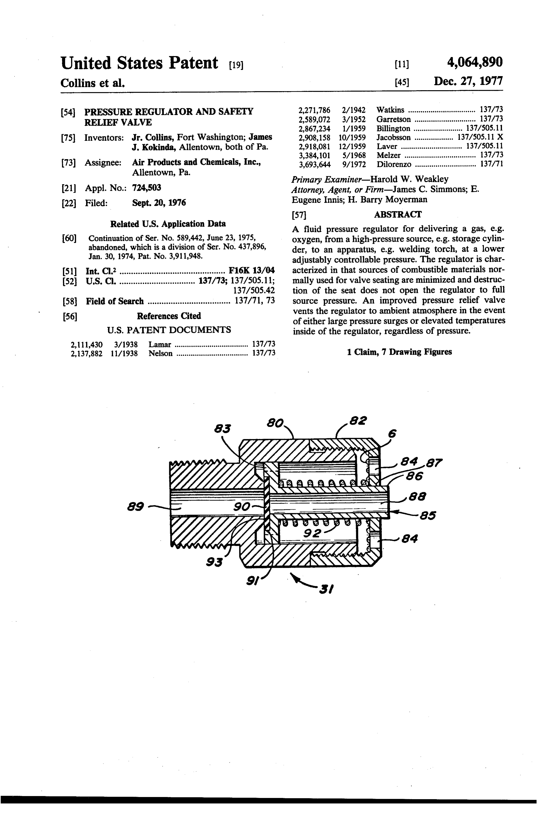
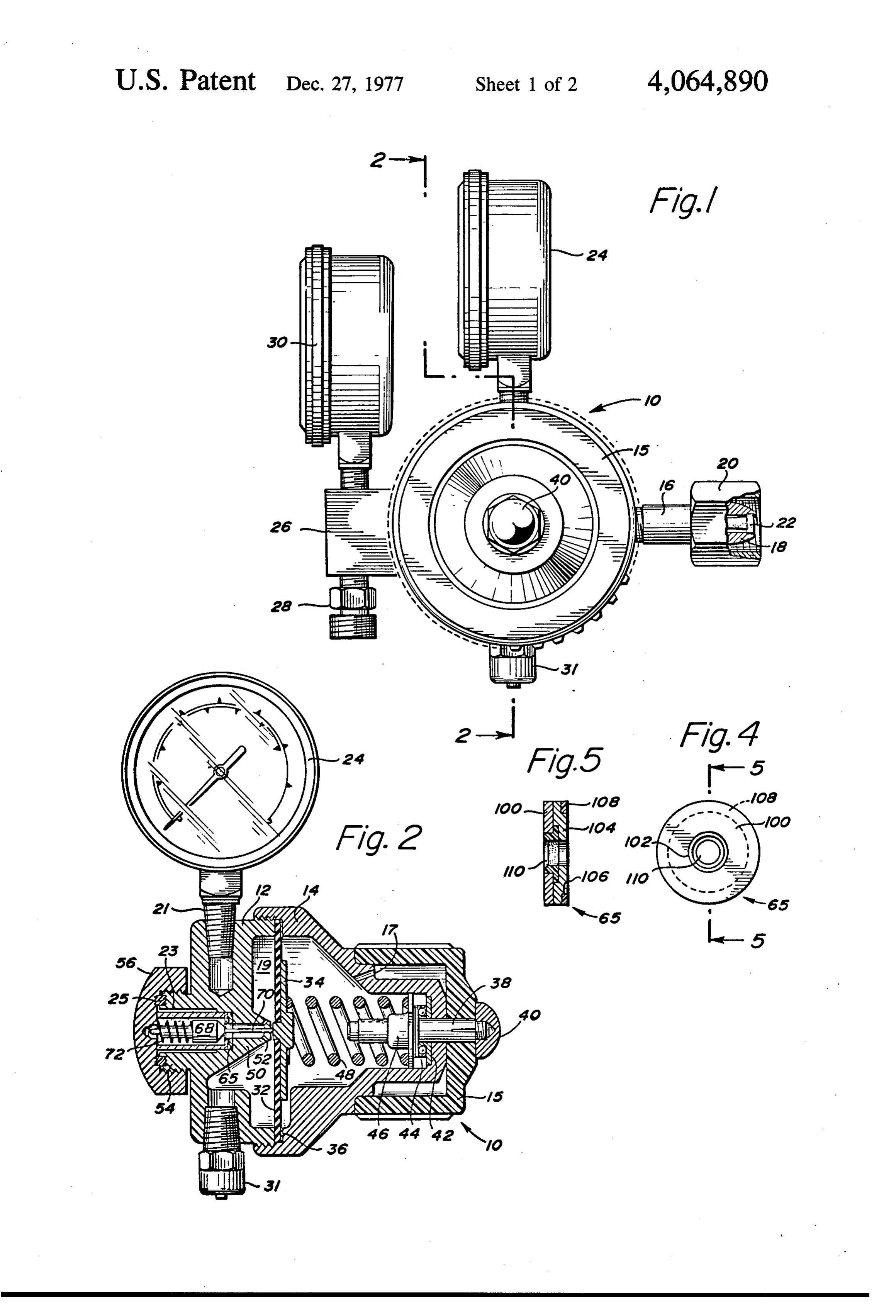
This is a continuation of application Ser. No. 589,442 provide filed June 23, 1975 now abandoned which was a divi- 5 a pressure regulator that will vent internal com sion of application Ser. No. 437,896 filed Jan. 30, 1974, bustion in a safe manner. m now U.S. Pat. No. 3,911,948. . . .. .. BRIEF DESCRIPTION OF THE DRAWING BACKGROUND OF THE INVENTION FIG. 1 is a front elevational view of a pressure regula This invention pertains to pressure regulators of the 10 tor according to the present invention. type used to control the pressure of a fluid usually in FIG. 2 is a section taken along the line 2-2 of FIG. gaseous form as it is withdrawn from a receptacle 1.
where it is normally stored at high pressures, e.g. in FIG. 3 is an enlarged sectional view of the body of excess of 500 psi. Such regulators are commonly em the regulator with pressure gauge and relief valve re ployed to deliver the fluid to a point of use such as an 1 FIG. 4 is an end view of the valve seat of the present
oxygen mask or a welding torch from a cylinder of oxygen at delivery pressures of less than 150 psi. The invention.
fluid pressure regulator devices include a manually 4. FIG. 5 is the section taken along the line 5-5 of FIG. operable control knob for adjusting the desired delivery 20 pressure regardless of the source pressure involved. FIG. 6 is an end view of the safety relief valve ac Pressure regulators of the type disclosed in this appli cording to the present invention. cation are illustrated by U.S. Pat. Nos. 2,115,512, FIG. 7 is a section taken along the line 7-7 of FIG.
2,918,081, and 3,547,143. In particular, the regulator of 25 DETAILED DESCRIPTION OF THE this invention is an improvement over the fluid pressure PREFERRED EMBODIMENT regulators disclosed in U.S. Pat. Nos. 2,918,081 and Gas pressure regulators such as shown in the drawing 3,536,092, which patents are owned by the Assignee of and, in particular, FIGS. 1 and 2 are used for delivering the present invention. . . . .
With the prior art regulators such as shown in U.S. 30 alessgasthan (oxygen) to a point of use at a pressure of usually 150 psi. In the medical field, oxygen is deliv
Pat. No. 2,918,081, when the regulator is used to control ered to a mask or other breathing device for use with a the delivery of oxygen from a high-pressure source, patient. In welding applications, the oxygen is usually which source is usually in excess of 500 psi, if there are delivered via a hose to a welding torch. The oxygen is contaminants inside the regulator such as grease, rust, normally stored at pressures in excess of 500 psi in a or hydrocarbons in the presence of pure oxygen, these 35 receptacle such as individual cylinders or large storage contaminants will act as fuel. The regulator materials tanks. The regulator functions to safely reduce the high such as elastomeric materials used to provide the valve container pressure of the gas and deliver it to the lower seat will under certain conditions ignite to act as fuel. pressure for usage.
For example, ignition energy can be supplied by heat of If an oxygen regulator is not properly maintained or recompression which is heat generated by the expansion 40 operated with care, a combination of conditions can and sudden compression of oxygen or by particles of exist which under certain operating conditions can contamination impinging on the internal surfaces of the cause the regulator to either burn out or explode. Such regulator. This condition can exist when a regulator occasions are rare, but they do happen. Contaminants valve is opened rather quickly. If this condition does within the oxygen regulator such as grease, rust, or exist and ignition takes place, the seat is consumed with 45 hydrocarbons will act as a fuel in the presence of pure the resultant explosion of the regulator. While such oxygen. Sometimes a regulator material, e.g. stainless explosions are rare, they nonetheless do happen. steel, will act as fuel and support combustion. This is SUMMARY OF THE INVENTION true because all materials in the presence of high-pres sure oxygen (above 500 psi) will burn vigorously.
In order to provide an improved regulator, it has so The ignition of the combustible materials can be sup been discovered that sources of fuel inside the regulator plied by the heat of recompression. This condition hap can be minimized by selecting the proper materials of pens or can happen when a regulator valve is suddenly construction and particularly by providing a multipiece opened to expose the internal portions to the high-pres valve seat wherein combustible materials necessary for Sure oxygen.
sealing the valve are held to an absolute minimum. 55 In order to minimize the sources of possible combus Furthermore, a safety relief valve that is responsive to tion, it has been discovered that certain materials, usu pressure surges and to elevated temperature indepen ally plastic or elastomeric in nature, conventionally dent of pressure inside the regulator aids in preventing used to provide sealing of the pressure control valve combustion contained inside the regulator. The im should be used in minimum quantities to minimize the proved relief-valve is achieved by having a readily energy release if combustion is started. Furthermore, fusible element to open the relief valve at a preset tem the combustion of such materials should not render the perature independent of the pressure inside the regula valve inoperative thereby producing large quantities of to... . . . . . . . i combustion supporting gas, e.g. oxygen. It has been Therefore, it is the primary object of the present shown that in order to maximize safety and minimize invention to provide an improved pressure regulator. 65 effects of internal combustion, the regulator must have It is another object of the present invention to pro means to rapidly remove excess gas build-up and to vide a regulator having minimal fuel sources contained minimize exposure of the internal parts of the regulator within the regulator. to elevated temperatures thus preventing propagation
Page 5
of combustion. By combination temperature and pres backing plate 34. Thus, as the diaphragm 32 moves to sure sensitive safety valve, these ends can be achieved. the left, the valve stem 68 is pushed to the left and the There is shown in FIG. 1 a pressure regulator 10 that high-pressure fluid passes into the low-pressure cham is ideally suited for controlling withdrawal of oxygen ber 19. . from a source of high pressure. Although regulator 10 is 5 As shown in FIG. 3, the cap 56 is sealed to the body ideally suited for oxygen, it can be used for any of the 12 by means of complimentary grooves or ridges 60, 62 gases, normally dispensed from cylinders and the like. between which is placed a sealing member 25. The The regulator 10 includes a body 12 (FIG. 2) and a projection 54 of body 12 has suitable threaded connec bonnet 14 (FIG. 2) threadably connected to define a tions for facilitating removal of the cap to service the chamber. Regulator 10 includes an inlet conduit 16 with 10 regulator. It should be noted that the element 25 is a suitable nut or fastener 20 for connecting the inlet preferably of a fluorocarbon plastic material sold under conduit 16 to a source of high-pressure gas, e.g. a cylin the tradename KEL-F and has, because of annular lip 27 der. Inlet conduit 16 has a rounded nose 18 to mate with on projection 54, minimum surface exposed to the high the corresponding fitting on the source of gas and fur pressure gas while forming an effective seal. In prior art ther includes a porous filter element 22, to filter contam 15 regulators, the cap is usually provided with a fluidtight inant particles from the gas. Regulator 10 has an outlet seal by an O-ring disposed between the cap 56 and a flat 26 containing a fitting 28 for receiving a hose or other surface on the end of projection 54. delivery device. The regulator includes a safety relief The cap 56 forces the porous filter 66 against the valve 31, a control knob 15, high-pressure gauge 24, and valve seat 65, thus providing a seal between the filter low-pressure gauge 30. and the valve seat so that all entering gas comes through Referring to FIG. 2, the valve body 12 and bonnet 14 the filter.
are separated by a resilient diaphragm 32, which dia Also, filter 66 presses seat assembly 65 into the bot phragm is usually constructed from neoprene rubber. tom of the counterbore (chamber 64) in body 12 sealing One face of the diaphragm 32 has an annular ring 36 of against body 12 by seal 108 (FIG. 5) thus preventing gas a metal such as brass to provide strength at the periph- 25 from leaking around seat 65 into low-pressure chamber eral sealing edge and a backing plate 34 to provide a 19.
bearing surface for spring 48. Projecting through the There is shown in FIGS. 4 and 5 an improved valve end of bonnet 14 and rotatably mounted therein is a seat 65 consisting of a first flat washer 100, a second spindle:38. In communication with spindle 38 is bearing having a central aperture 102. Mating with the first 44, bearing plate 42 and follower nut 46 to control com- 30 washer 100 is a second washer 104 containing on its pression and relaxation of spring 48. The projecting end outer surface an annular recess or groove 106. The of spindle 38 has knob 15 affixed thereto by means of washer 104 has an internal diameter defining the maxi end nut 40. As the knob 15 is rotated, the spring can be mum regulator valve opening which is smaller than the compressed to urge the diaphragm to the left as shown internal diameter of washer 100. It also contains an in FIG.2. As the cap is rotated in the opposite direction, 35 enlarged portion of the inside diameter so that in cross compression on the spring is decreased and the dia section, the ring 104 has a Z-shaped appearance. phragm 32 returns to its normal position such as shown Groove 106 is made to receive a sealing member such as in FIG. 2. The bonnet 14 contains suitable vent holes 17 a KEL-F washer. AKEL-F member 110 in the shape of so that the chamber defined by the bonnet 14 and dia a stepped flange is inserted between washers 100 and phragm.42 is maintained at ambient pressure. 104 and provides the valve seating member. The flange The body 12 of regulator 10 and the diaphragm 32 110 has an inside diameter equal to the inside diameter define a low-pressure chamber 19. As shown in FIG. 2, of washer 104 and can contain a chamfered end 111 as communicating with the low-pressure chamber 19 is a shown to mate with the tapered end of valve stem 68. pressure relief valve 31, the function of which will be The seat 65 is assembled into the regulator as shown in explained in greater detail hereinafter. 45 FIG. 3 so that the plate 104 is held by the counterbore The body; 12 has a suitable fitting 21 for receiving in section 50 of the body 12 with a fluid seal being pro low-pressure gauge 24 as shown and on the opposite vided by the washer 106. Valve seat member 110 faces end from the diaphragm32 a projection 54 for receiving the valve stem 68 and provides the sealing means when end cap 56. valve stem 68 is extended against the member 110. The As shown in FIG. 2, the low-pressure gas enters the resilient material is needed to account for or to provide chamber 19 defined by body 12 and diaphragm 32 a seal if there should be a slight misalignment of the through ports 52 in projection 50 which projection valve stem or wear on the valve stem before the normal defines the forward end of and encloses the high-pres maintenance period has expired. - a sure chamber 64 of the regulator. The high-pressure gas In the preferred construction of the regulator as is introduced into the high-pressure chamber 64, which 55 shown in FIGS. 1 and 2, the body 12 and bonnet 14 of is defined by body 12, projection 50, projection 54, and the regulator are made of brass. Tests have shown that the cap 56, through a conduit (not shown) as is well stainless steel is more easily ignited in the presence of known in the art. The entering gas passes through a high-pressure oxygen than other materials. Therefore, porous filter 66 into the area surrounding the valve stem the activating pin 70 is fabricated from an iron-chromi 68, past the valve stem 68 through valve seat. 65, past um-nickel alloy sold under the tradename of INCO valve pin 70, out ports 52 into the low-pressure chamber NEL, the valve stem 68 and porous filter 66 are fabri 19. The opening between valve stem 68 and valve seat cated from a nickel-copper alloy sold under the trade 65 controls the delivery pressure of the gas. As shown name of MONEL and the spring 72 is preferably fabri in FIG.3, the valve pin 70 is normally urged toward the cated from INCONEL. The valve seat 65 is fabricated valve seat 65 by a spring 72. The valve stem is opened from brass (members 100 and 104) and a synthetic mate by pushing the valve stem 68 toward the left (end cap rial KEL-F (Members 106 and 110). The KEL-F mate 56) by means of activating pin 70, which projects rial has been found to be more fire resistant than prior through the body 12 and bears on the diaphragm 32 materials such as neoprene rubber, and the like.
Page 6
With this combination of materials, the following The retractable, spring-loaded relief valve 31 without benefits are achieved. The four-part seat exposes only the fusible element 90 would not activate unless a preset the smallest amount of elastomeric material (KEL-F) to pressure level was exceeded. Such preset pressures are the oxygen since there is just enough exposed elasto usually on the order of 75 to 250 psig for oxygen. If the meric material to seat the valve stem 68. The two brass valve seat is consumed by combustion inside the regula pieces 100 and 104 act as a large heat sink. If the small tor and the pressure is less than the minimum pressure at amount of KEL-F contained in member 110 is ignited which the valve 31 is set to open, the elastomeric mem and consumed, the valve stem 68 can still close against ber 90 will be consumed and the combustion reaction the surrounding brass or metal in members 100 and 104. 10 will be vented to the atmosphere thus minimizing the Furthermore, because the soft seating material 110 is effects of reaction by containing the reaction first in the supported by the brass, less deformation and longer seat regulator and then directing it away from the regulator. life can be expected. The KEL-F washer 106 is com In the normal course of events, the reaction would start in the high-pressure chamber and if it moves to the pletely surrounded by brass and, therefore, would not low-pressure be exposed to elevated temperatures since the brass 15 causing chamber, the diaphragm could burn thus cataclysmic failure of the regulator. With the pieces 100 and 104 act as a heat sink. The minimization interposition of the fusible element 90 in the safety relief of the presence of consumable fuel (KEL-F, nylon or valve 31, the valve willopen thus removing the combus the like) such as shown in the valve seat in connection with the regulator of U.S. Pat. No. 2,918,081 prevents tionAsfrom
the regulator and protecting the diaphragm.
apparent in order to protect the regulator, the large flows of high-pressure oxygen from continuing 20 gas must be removed through the regulator thereby providing secondary side to prevent burning quickly from the low-pressure reactions. In the regulator shown in FIGS. 1, 2, and 3, time and temperature. This is achieved bybytheminimizing of the diaphragm the greatest surface areas facing the reaction are of member 90 which burns and conducts productsneoprene of con metal, such as brass, having a low auto ignition point which resists combustion. Furthermore, the brass mem 25 bustion and gases out of the regulator thus the neoprene member 90 acts as a fuse.
bers of the valve seat conduct heat away from the It is apparent that other materials can be substituted KEL-F or other elastomeric materials. As stated above, for those disclosed herein. However, the minimization even if the KEL-F material is deformed or consumed, of the combustible materials and the use of a fusible the valve stem 68 can seat against the metal thereby element in the safety relief valve act in concert to retarding the flow of oxygen. achieve the overall improved regulator. There is shown in FIGS. 6 and 7 an improved safety Having thus described our invention, what we desire relief valve shown as 31 in FIGS. 1-3. The safety relief to be secured by Letters Patent of the United States is valve 31 includes abody 80 with an end cap 82 affixed set forth in the following claims. thereto as by threads as shown in the drawing. The cap We claim:
82 contains vent holes 84 for conducting vented pres 35 1. In an oxygen pressure regulator for maintaining surized fluid away from the valve 31. Disposed within constant lower pressure of oxygen gas delivered from a the valve housing 80 and cap 82 is a valve stem 85 com relatively high pressure source of the type including a prising a body 86 and closure member 83 having a cen casing having an internal flexible diaphragm dividing tral bore 88. The valve stem 85 projects through a suit said casing into two major chambers, one chamber able aperture 87 in cap 82. The valve stem 85 bears being vented to the atmosphere and containing adjust against the raised lip 93 of inlet port 89 and is closed by able resilient means for exerting a predetermined con an elastomeric member 90 disposed within a recess 91 in stant pressure against the diaphragm, and the other end closure member 83 of the valve stem 85 as shown. chamber being a gas chamber divided into two sub The preferred material for elastomeric member 90 is chambers, a first inlet sub-chamber for receiving said neoprene rubber. 45 high pressure gas and a second outlet sub-chamber for The closure member 83 of valve stem 85 bearing accumulating and delivering said gas at a lower pres against the inlet port 89 is a square or hex within a sure to an outlet means provided with valve-controlled cylinder or has radial grooves or slots to allow passage inlet means connectable between said first and second of the gas from the inlet port 89 to the vent holes 84. sub-chambers to regulate the pressure of said gas in said The valve stem is urged against the inlet port 89 by 50 outlet sub-chamber, the improvement comprising: means of an element 92 such as a coil spring. Inlet port a pressure relief valve in communication with said 89 includes the raised lip portion 93 which concentrates outlet sub-chamber, comprising in combination; compressive forces on member 90 thus effecting an a generally cylindrical housing having an inlet port improved seal. In the event of large pressure surges at and an outlet port said outlet port closed by a cap the inlet 89, the valve stem 86 moves toward the right 55 threadably engaging said housing, said cap having compressing spring 92 thus allowing the gas to flow into a plurality of apertures defining a flow path from the relief valve and out of the holes 84. In the event of said housing to the atmosphere; combustion inside of the regulator at lower pressures a valve closure member in the form of a stepped than that which would cause the valve to open, the cylinder having a T-shaped cross-section with a elastomeric member 90 is consumed and the gas and generally cylindrical bore through said valve clo combustion products are conducted away from the sure, said bore closed by a single combustible elas regulator through bore 88 in valve stem 85. As shown in tomeric element and also being positioned to close FIGS. 1 and 2, the safety relief valve 31 is mounted so said inlet port, said valve closure slidably disposed that any combustion products are directed downwardly within said housing and extending outwardly of away from the valve. In the normal operating position 65 said cap through a suitable aperture therein said of regulator 10, the safety valve points toward the floor, valve closure member exterior and said housing away from the connection with the source of high-pres coacting to effect a first passage means to allow sure fluid. passage of fluid from said inlet port to said outlet
Page 7
port when pressure in said outlet sub-chamber ex- on such spring to adjust the pressure at which said ceeds a given value; valve will open;
a spring disposed around the longer of the cylindrical whereby if combustion occurs inside said regulator, sections of said valve closure and extending be tween the base of said cylindrical section of said 5 said combustible element will be consumed regard closure and said cap to urge said valve closure less of the pressure on said valve closure member, member toward said inlet port to prevent passage thus venting said combustion from said regulator to of gas until the gas pressure at the inlet exceeds a prevent cataclysmic failure of said regulator. preset limit said cap movable to adjust the tension k
Provenance
- Collection
- Cited prior art
- Original PDF
- patentimages.storage.googleapis.com →
- Filed
- 1976-09-20
- Pages
- 7
- Method
- pdftotext (the PDF's own text layer) + pdftoppm 300dpi page scans
- Source
- Google Patents bibliographic record
- Granted
- 1977-12-27
- Inventors
- Jr. Collins; James J. Kokinda; Air Products and Chemicals Inc
- Transcribed from
- patentimages.storage.googleapis.com →