patent · US3738828
Method of powder activation
12 June 1973
Page 1
Drawing sheet — no readable text.
Page 2
Drawing sheet — no readable text.
Page 3
Drawing sheet — no readable text.
Page 4
UnitedStates PatentOfce 3,738,828 Patented June12,1973
Inadditiontoremovalofthe coatedflms,markedin 3,738,828 creases of surface tensionandfreeenergy ofthe cleaned ?4?THOD?E P?WDERACTIVATION Surfacesare achieved,and thisaction isespecialy re KiyoshiInoue,16—8,3-chome Kamiyoga,Tokyo,Japan narkable withions or heavy particles of suitably regu Continuation-in-partofapplicationSer,No.692,960, latedenergy.Thus,the beam particksactashigh-energy Dec.22,1967.ThisappicationJuly31,1979,Ser? impact media and strike atomsatthe surface region of No.60,070 each particle substrate,and by scattering they thereby
U.S?CI?75–21? 16CIaims produce Strain and distortion?n the powder particles
The power supply forthe production ofefective co
ABSTRACT OF TH?DISCLOSURE rona and glow discharge may be a Source of DC,AC, Amethodforactivation of metalic powders by Sub DC-pulse or pulsating current,Experimentation has jectingthe powderto bombardmentwithelectrons,ions, demOnStrated that a high-frequency and unidirectional ormoleculesin an inert orreductive atmosphere·Im currentispreferablein promotingpowderactivation,An proved densities result in sintering,as do improved electron beam Orion beam gun may beemployed? catalytic actions?Simultaneous pulverization of coarse Formanyapplications,itis preferred to use a beam particles orbodiesis alsoachieved where desired?The ofions(i.e.,heavy particles or particles of atomic or pretreatmentis,in someinstances,combinedwth 1oad molecular size and mass)as a corpuscular beam for ingtheactivated particles directyintoa mold,for com? impact powderactivation?
paction or sintering,preferably with Some additional 20 andTheinventionisapplicablenotonlytometalpowders to powders of metal aloys,but also,in some
aspects to powdered metal oxides,other metalic com
Thisapplicationisa continuation-in-part of appica A highly activated powder,which exhibits excelent tionSer.No.692.960,fled Dec.22,1967,now Pat?No… 25 performance in metalurgical,chemicalorelectrochemi 3.598.566. calutilization(i.e,interms of metalurgical bondability, Thisinvention relatestometalic powderactivation… ?hysical properties,chemicalorelectrochemicalactivity) Moreparticulady,itrelatesto animproved method.9f is obtained by bombardment of corpuscular particles, andapparatusfortheremovalofimpuritiessuchas9xide especialy ions or particles atleastin part formed by flmandmoisture,aswelasother contamination,from 30 ions,particles of atomic or molecular size and mass, ?esurfacesofdiscretemetalic particlesbyutizingim which when they are impartedimpactenergy sufcient pactenergy.Theresultistomodifysuch Su?acestoan toform?attice defects(e.g,of Frenkeltype)andaccom panyinglattice dislocationsintheindividualparticles of activated powderthatmay be used for cold o?warm pressingto form densifed green compacts or for hot Powder?
pressingto produce coherentsintered objects or forin 35 In accordance with another aspect of the invention, {erpartclechemicalreactionsorforcatalyst· simultaneously with activation,pulverization ofrelative Conventionaly,two powderactivation processes have ly large-sized particles or bodies(wire,block,etc.)into beenavaiable:(a)heafnginareductiveatmosphereand Smalersized particles can be efected by means ofim (b)reaction with particular chemicaLagents, Each of Pulses of discharge energy. Forthis purpose,fuidized theseprocesseshashadonlylimitedefciency. 40 powder may be held between a pair ofelectrodesina The presentinvention comprises introducing fowder non-oxidizingatmosphere soasto be subjected tointer intoaninertorreductiveatmosphereandtheresubjecting 1particle discharges of impulsive character under the itto bombardmentwith high-energyimpact force by externalappication of a succession ofimpulses across electrons,ions,ormolecules or combinationsthereP? the electrodes?Alternatively,a spark gap of relatively Electronandion bombardmentfor purposes ofthis 45 Smallspacing may be surroundedbyfoating powderso inventionmaybeefectedthroughanelectricalsp8° dis thatuponthegeneration ofimpulsedischargeatthegap, charge,eg,corona orgow discharge,created through nechanical colisions may be inducedamong particles the?ertörreductive medium betweena pair of sleS… and propagated radialy outfrom the spark gap?The Todeoramongadjacentorclosediscreteparticlesfüd Darticlesizeresultingfromsuch pulverizingmaybecon ?edin the ?ert or reductive medium?Molecular 50 troled byregulation ofthe discharge energy. B6mbardment,probaby with some accompanyingio? The presentinvention alsoprovidesanimproved pow bombardment,maybeaccomplishedbyshockwayes, such derloadingsystem wherein powderis pre-treatedas de asresutfrom detonationina shockgun,as by spark Scribedabove,andisthereafterimmediately1oadedina generation ofimpulses… mold for compaction orsintering?Such asystem ofers Thavediscoveredthattheeectron,ionormolecular 55 duringloading?
the opporfunityforfurtherbombardmentandpurifcation bombardment advantageousy removes oxide flms, moisture,adsorptivegaseousparticlesand9therjmpu° Other objectsandadvantages oftheinvention wilap tiesnormalyfrmiyadherentto and coated9n the sub pearfrom the folowing description of some preferred strate ofeach discrete particle,apparenty by decom? embodiments?
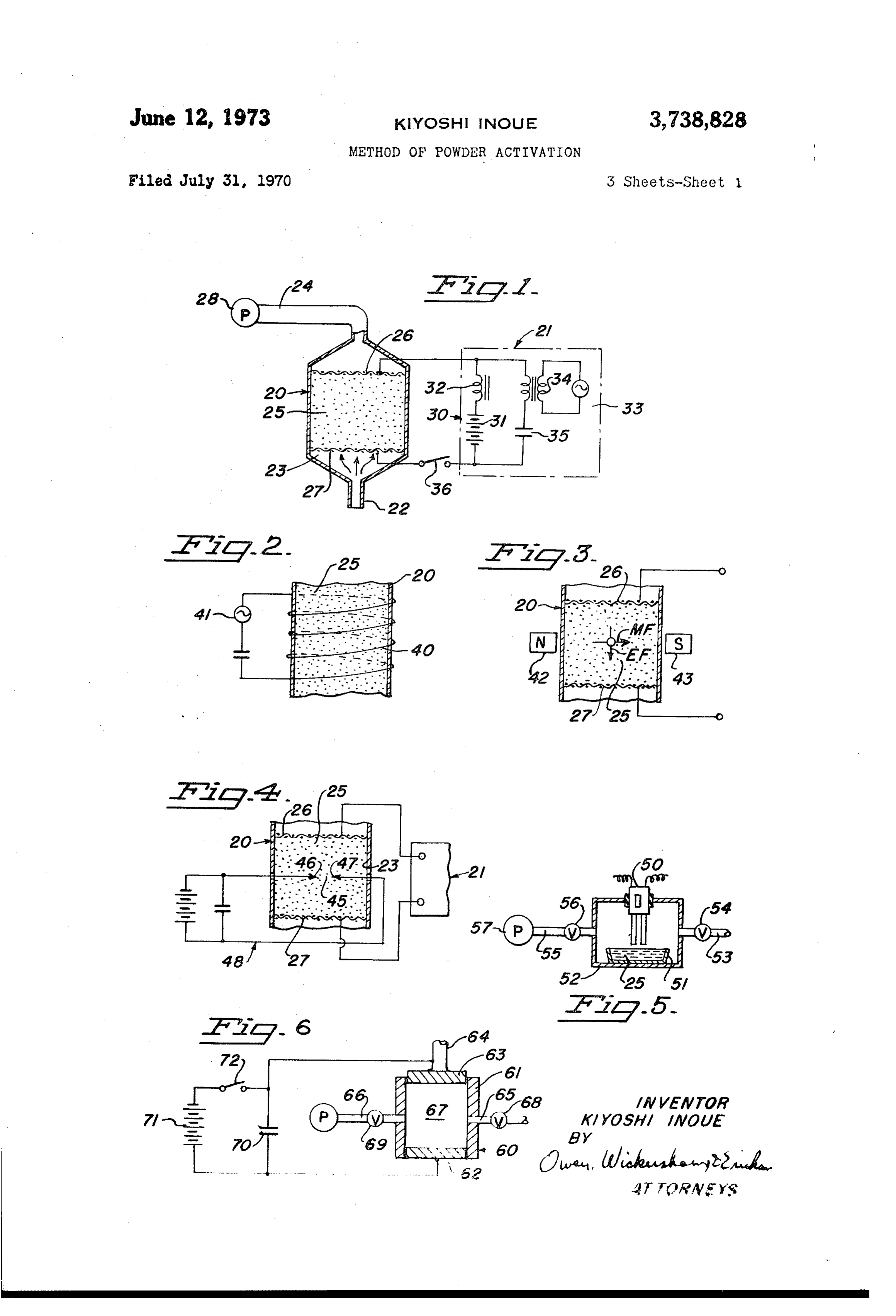
posingtheseimpurities_intogasepus substances,thereby 60 Inthe drawings:
öean?gthesurfaces ofthe particles madditio?tor? FIG?1isa diagrammatic view ofasystemembodying möva?of the coated flms by the action 9f Such the invention,includinga treatment chambershownin Bombardment,markedincreases of surfacetenson and elevationandin Sectionandanelectricalcircuit? freeenergyofthe cleanedsufaces3réachsved?sar? FIG?2isa fragmentaryand diagrammatic view ofa sultoftRéformation ofstrainand distortion_By Con 65 portion ofa modified form oftreatmentchamber ofthe
itsreplenishment byintroducingfresh inertorreductive invention with a diferentmeansforapplyingthe electri gasito and evacuating_the co??inated atmosphere calcircuittothe chamber?
?6mthetreatmentchamberin whichthe bombardment FIG.3isa viewsimilarto FIG?2ofanother modifed isefected,the decompoSed?gaSeous impuritiesare pre 70 form oftheinvention,employinga magnetic feldincom Ven?áfromrecombiningwiththe materialformingthe bination with the apparatus of FIG.1? particlesubstrate, FIG,4isaviewsimiarto FIG,1ofanother modifed
Page 5
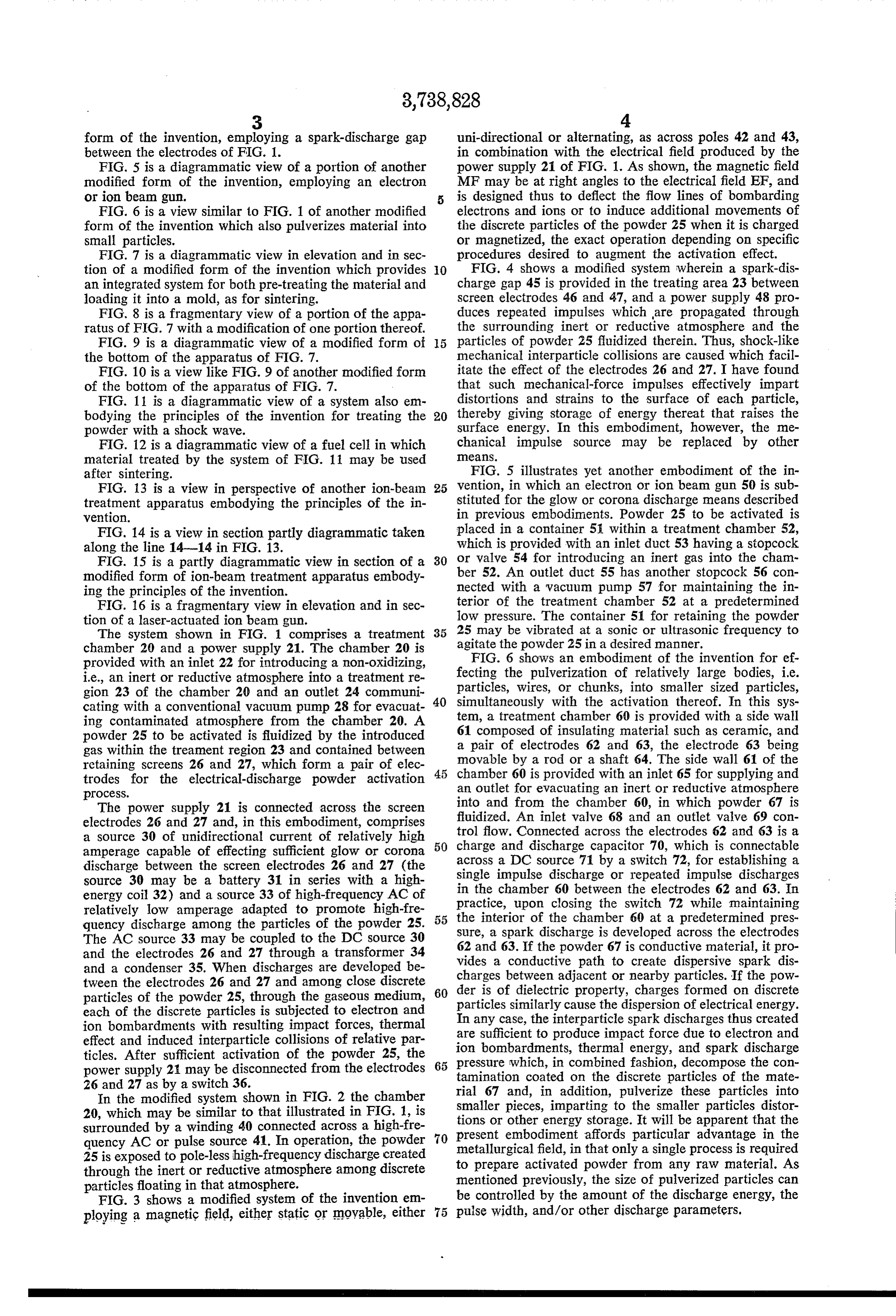
form of the invention,employinga Spark-discharge gap uni-directionaloraiternating,asacross poles42and43, betweenthe electrodes of FIG?1? in combination with the electricalfield produced by the FIG,5isa diagrammatic view ofa portion ofanother powersupply21of FIG.1.Asshown,the magnetic feld modified form of the invention,employing an electron MFmaybeatrightanglestothe electricalfeld EF,and orion beamgun? is designed thusto defect the fow lines of bombarding FIG,6isaviewsimilarto FIG.1ofanothermodifed electronsandions ortoinduce additionalmovements of form oftheinvention whichalsopulverizes materialinto the discrete particles ofthe powder25whenitischarged Smal particles? ormagnetized,the eXactoperation dependingon Specific FIG.7isa diagrammatic viewin elevation andin sec Procedures desired to augment the activation efect? tion of a modified form of the invention which provides FIG,4shows a modified system whereina Spark-ds anintegratedsystemforboth pre-treatingthe materialand charge gap45is providedin the treatingarea23 between 1oadingitinto a mold,as forsintering? screenelectrodes46and47,anda powerSupply48 pro FIG,8isafragmentaryview ofaportion oftheappa duces repeated impulses whichare propagated through ratus of FIG.7withamodification ofoneportionthereof the surrounding inert or reductive atmosphere and the FIG.9 isa diagrammatic view of a modifedform of particles of powder25fuidized therein.Thus,shock-like the bottom oftheapparatus of FIG.7? nechanicalinterparticle colisionsare caused which facil F[G?10isaview like FIG?9ofanother modifiedform itate the efectof the electrodes26and27.I have found ofthe bottom oftheapparatusof FIG.7? that such mechanical-force impulses efectively impart FIG?11isa diagrammatic view of a system also em distortions and strains to the Surface of each particle, bodyingthe principles of the invention fortreating the 20 thereby giving storage ofenergy thereatthatraises the Dowderwithashockwave? surface energy,In this embodiment,however,the me FIG.12isa diagrammatic view ofafuelcelin which chanical impulse Source may be replaced by other materialtreated by the system of FIG.11 may be used ?lé3?S?
after sintering? FIG,5ilustrates yetanother embodiment of the in FIG?13isa viewin perspective of anotherion-beam 26 vention,in which an electron orion beam gun50issub treatmentapparatusembodyingthe principles of the in stitutedfortheglow orcorona discharge meansdescribed vention? in previous embodiments?Powder25to beactivatedis FIG?14isaviewinsection partlydiagrammatictaken Blacedina container5?withinatreatmentchamber52, alongtheline14?14in FIG.13. whichis providedwithaninletduct53 havingastopcock FIG?15isa party diagrammatic viewinsection ofa 30 or valve 54forintroducingan inertgasinto the cham nodifedform ofion-beamtreatmentapparatusembody Der52?An outletduct55 hasanother stopcock56con ingthe principles oftheinvention? nected with a vacuum pump 57formaintainingthe in FIG?16isafragmentaryviewinelevationandin Sec terior of the treatmentchamber 52ata predetermined tion ofalaser-actuatedion beam gun? 1ow pressure.The container51forretainingthe powder The system shown in FIG,1 comprisesa treatment 35 25 may be vibratedatasonic or ultrasonic frequencyto
chamber29anda powersupply21?The chamber20is FIG?6showsan embodiment of the inVention foref provided withaniniet22forintroducinga non-oxidizing, ie.,aninertorreductiveatmosphereintoatreatmentre fecting the pulverization of relatively large bodes,ie? gion23of the chamber20andan outlet24communi particles,wires,or chunks,into smallersized particles, catingwith a conventionalvacuum pump28forevacuat 40 simultaneousy with the activation thereof,In this sys ing contaminated atmosphere from the chamber20,A tem,a treatmentchamber60is provided withaside wal powder25to be activatedisfuidized bytheintroduced 61composed ofinsulating materialsuch asceramic,and gas withinthe treamentregion23and contained between a pair of electrodes 62and 63,the electrode 63 being movable byarod orashaft64.Thesidewa161 ofthe retaining screens26and 27,which forma pair of elec 45 chamber60isprovidedwithaninlet65forsupplyingand trodes for the electrical-discharge powder activation anoutletforevacuatinganinertorreductive atmosphere
The powersupply 21 is connected across the screen into and from the chamber 60,in which powder 67is electrodes26and27and,in thisembodiment,comprises fiuidized?Aninlet vajve 68and an outlet valve 69con a source 30 of unidirectional current of relatively high 50 trolfow,Connectedacrossthe charge and discharge
amperage capable of efecting Suficientglow or corona acrossa DCsource71byaswitch72,forestabishinga discharge between the screen electrodes26and27(the single impulse discharge orrepeatedimpulse discharges source 30 may be a battery31 in series with a high in the chamber 60 between the electrodes62and 63.In energy coi32)andasource33of high-frequencyACof practice,upon closing the switch 72 while maintaining relatively low amperage adapted to promote high-fre quencydischargeamongthe particks ofthe powder25, 55 the interior of the chamber60ata predetermined pres Sure,aspark dischargeis developed acrosstheelectrodes
The ACsource33may becoupled tothe DCsource30 62and63.Ifthepowder67isconductive material,itpro and the electrodes26and27through a transformer34 vides a conductive path to create dispersive spark dis andacondenser35,When dischargesare developed be charges betweenadjacentornearbyparticles?Ifthe pow tweentheelectrodes26and27andamongclose discrete deris of dielectric property,charges formed on discrete particlesofthe powder25,throughthegaseous medium, 60 particlessimilarlycausethe each ofthe discrete particlesissubjectedto electronand dispersion ofelectricalenergy? ion bombardmentswithresultingimpactforces,thermal In anycase,theinterparticiesparkdischargesthus Created are suficientto produceimpactforce duetoelectronand efectandinducedinterparticle colisionsofrelative par ion ticles?After suficientactivation of the powder 25,the bombardments,thermal energy,and spark discharge powersupply21maybedisconnectedfromtheelectrodes 65 pressure which,in combinedfashion,decomposethe con tamination coated on the discrete particles of the mate 26and27as byaswitch 36?
Inthemodfed system shown in FIG.2the chamber rial 67 and,in addition,puiverize these particles into 20,whichmaybesimilartothatilustratedin FIG.1,is smaler pieces,impartingto the smaler particles distor tionsorotherenergystorage?Itwil beapparentthatthe surrounded byawinding40connectedacrossa high-fre Dresentembodimentafords particular advantage in the quencyACorpulse source41?Inoperaton,the powde? 70 25isexposedtopole-lesshigh-frequencydischargeCreated metalurgicalfeld,inthatonlyasingle processisrequired to prepare activated powderfrom anyraw material?As throughtheinertorreductiveatmosphereamongdiscrete Tnentioned previously,the size of pulverized particlescan particlesfioatinginthatatmosphere, be controled bytheamountofthe dischargeenergy,the FIG.3showsamodifed system ofthe inventionem ployingamagneticfeld,etherstaticor?oyable,eiher 75 pulsewidth,and/orotherdischargeparameters,
Page 6
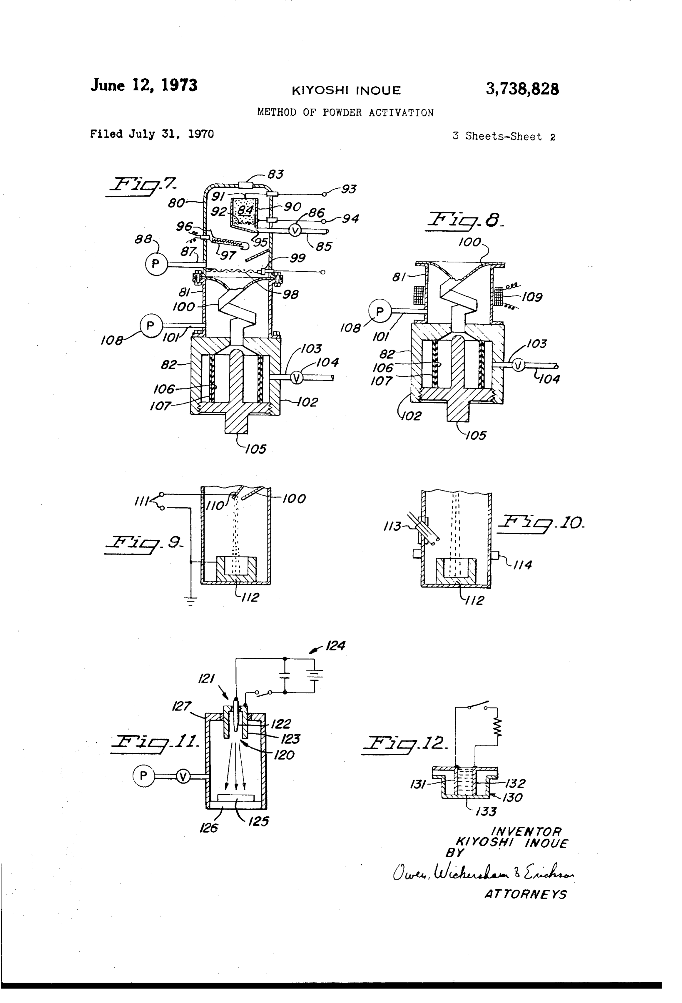
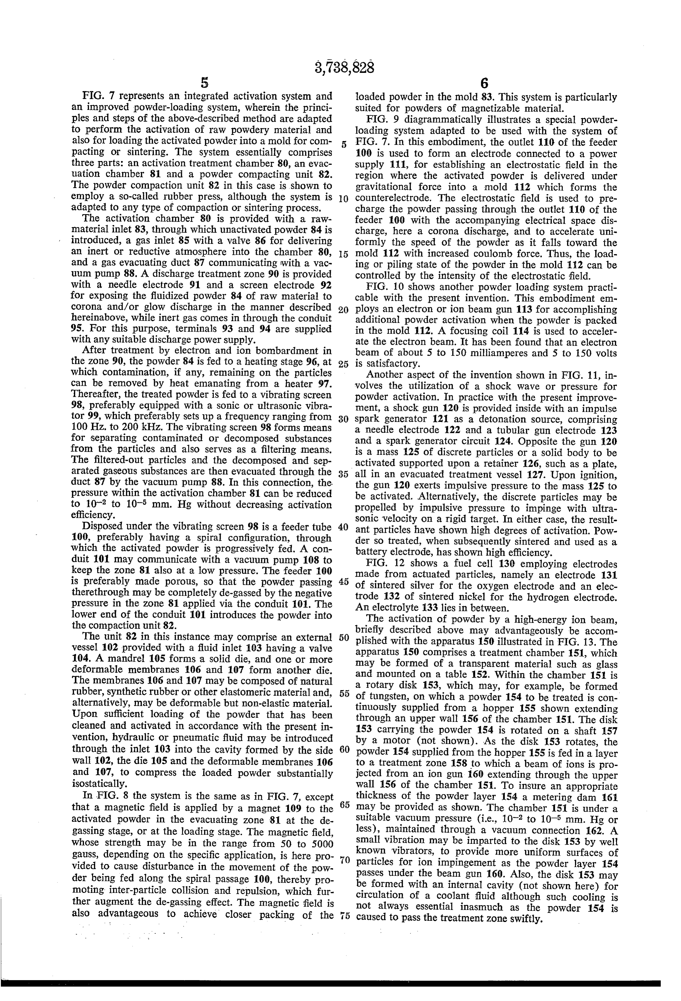
FIG.7representsanintegrated activation system and 1oaded powderinthemold83.Thissystemisparticularly animproved powder-loadingsystem,wherein the princi suited forpowders of magnetizable material? Plesandstepsoftheabove-described methodareadapted FIG,9 diagrammaticalyiustratesa special powder to perform the activation of raw powdery materialand 1oadingsystem adapted to be used with the system of alsoforloadingtheactivatedpowderintoamoldforcom FIG.7.Inthisembodiment,the outlet110 ofthe feeder pacting or sintering?The system essentialy comprises 100is used to form an electrode connected to a power three parts:anactivationtreatmentchamber80,anevac suppy1?1,forestablishingan electrostatic fieldin the uation chamber 81 and a powder compacting unit 82? region where the activated powder is delivered under The powder compaction unit82inthiscaseisshown to gravitational force into a mold 112 which forms the employaso-caledrubberpress,althoughthe systemis counterelectrode,The electrostatic field is used to pre adaptedtoanytype of compaction orsintering process, chargethe powderpassingthrough the outlet110 ofthe The activation chamber 80 is provided with a raw feeder 109 with the accompanyingelectricalspace dis materialinlet83,through whichunactivatedpowder84is charge,here a corona discharge,and to accelerate uni introduced,agasinlet85withavalve 86fordelivering formly the speed of the powder asit falstoward the an inert or reductive atmosphere into the chamber 80, 15 mold112with increased coulomb force,Thus,the load andagasevacuatingduct87communicatingwithavac ingorpilingstate of the powderinthe mold112can be uum pump88.Adischargetreatmentzone 90is provided controled bytheintensity ofthe electrostatic field. with a needle electrode 91 and a screen electrode 92 FIG.10showsanother powder1oadingsystem practi for exposingthe fuidized powder 84 ofraw materialto cable with the presentinvention,Thisembodimentem corona and/or glow discharge in the manner described 20 ploysanelectron orion beam gun113foraccomplishing hereinabove,whileinertgascomesinthroughthe conduit additional powderactivation when the powderis packed 95,Forthis purpose,terminals 93 and 94are supplied in the mold112,Afocusingcoi1114isused toacceler withanysuitabledischarge powersupply. ate theelectron beam,Ithas beenfoundthatanelectron Aftertreatment byelectronandion bombardmentin beam ofabout5to 150 miliamperesand 5to 150volts thezone90,thepowder84isfedtoaheatingstage 96,at 25 issatisfactory.
which contamination,ifany,remaining on the particles Anotheraspect oftheinvention shownin FIG.11,in can beremoved by heatemanatingfrom a heater 97. volves the utization of a shock Wave or pressure for Thereafter,thetreated powderisfedtoavibratingscreen ?owderactivation?In practice with the presentimprove 98,preferably equipped with a Sonicor ultrasonic vibra ment,ashockgun120isprovidedinside withanimpulse tor99,which preferablysetsupafrequencyrangingfrom 30 sparkgenerator121 asa detonation source,comprising 100Hz.to200 kHz.Thevibratingscreen98formsmeans a neede electrode 122andatubulargun electrode 123 forseparating contaminated or decomposed substances anda sparkgeneratorcircuit124,Oppositethe gun120 from the particles and also Serves asa fitering means? isa mass125 of discrete particles orasolid bodyto be The fitered-out particles and the decomposed and sep activated supported upon a retainer126,Suchasa plate, aratedgaseoussubstancesarethenevacuatedthroughthe 35 alinan evacuated treatmentvessel127.Uponignition, duct87 bythe vacuum pump88.Inthisconnection,the the gun120exertsimpulsive pressuretothe mass125to pressurewithintheactivation chamber81can bereduced be activated,Alternatively,the discrete particles may be to 10?°to 10?°mm?Hgwithout decreasingactivation Dropeled by impulsive pressure to impinge with ultra
Disposedunderthevibratingscreen98isafeedertube 40 sonic ant velocity onarigidtarget.Ineithercase,theresult particleshave shown high degrees ofactivation.Pow 100,preferably having a spiral configuration,through der So treated,when subsequentlysintered and usedasa which the activated powderis progressivelyfed?Acon batteryelectrode,hasshown higheficiency? duit101may communicate with avacuum pump108to FIG,12 shows a fuel cel130 employingelectrodes keepthezone 81alsoatalow pressure.Thefeeder100 is preferably made porous,so thatthe powder passing 45 nade from actuated particles,namely an electrode 131 of sintered siverforthe oxygen electrode andan elec therethroughmaybe completelyde-gassedbythe negative trode 132 of sintered nickelforthe hydrogen electrode? Dressurein the Zone 81applied viathe conduit101.The Anelectrolyte1331iesin between. 1owerend ofthe conduit101introducesthe powderinto The activation of powder bya high-energyion beam, the compactionunit82. briefy described above may advantageously be accom The unit82in thisinstance may comprise an external 50 plishedwith vessel102providedwithafiuidinlet193havingavalve apparatus150theapparatus150iustratedin FIG.13.The
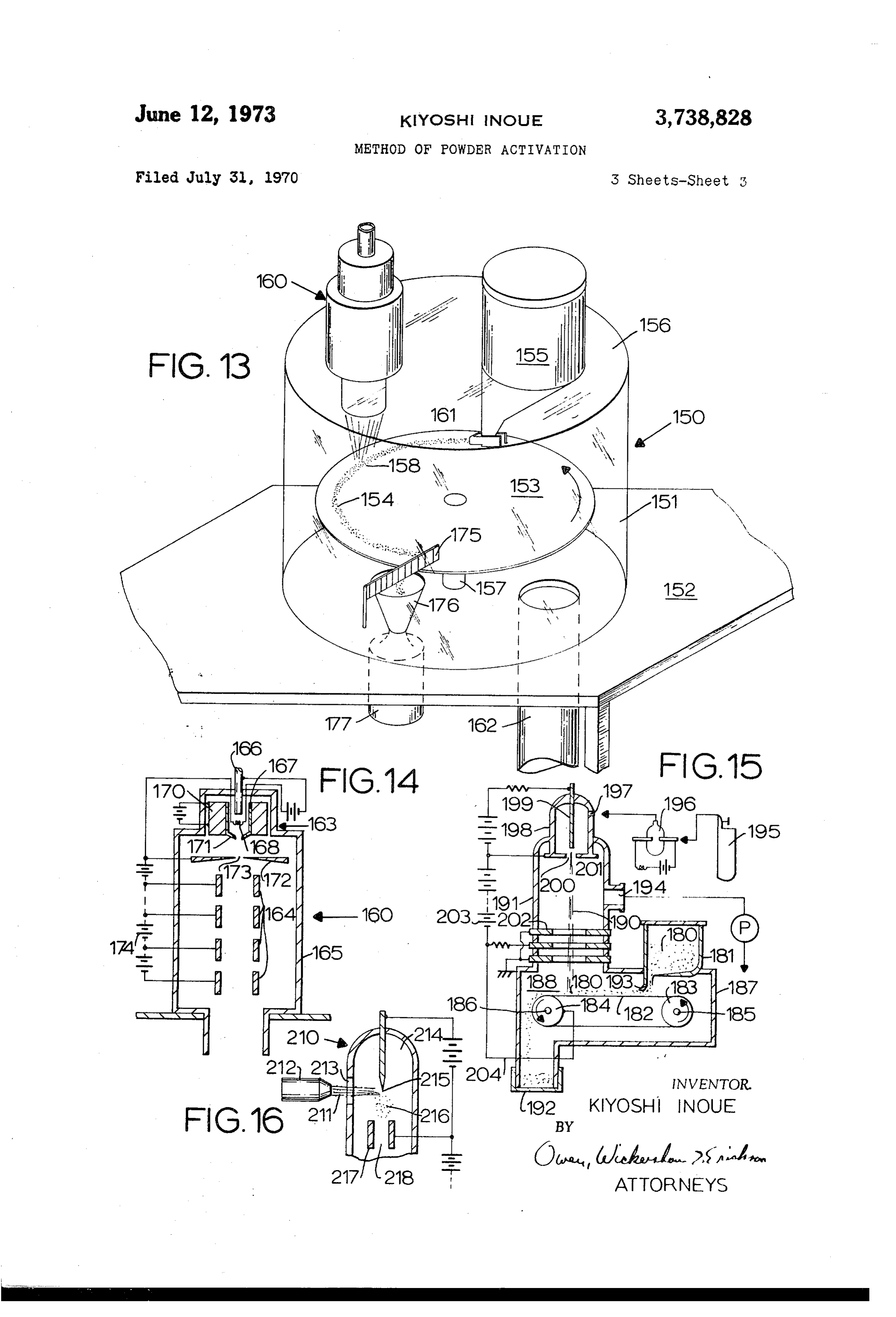
104,Amandrel105formsa solid die,and one ormore may be formed of a transparentmaterialsuch asglass <ieformable membranes 106and 107 form another die?
Themembranes196and107maybecomposed ofnatural aandrotary mounted onatable152. Withinthe chamber151is disk153,which may,forexample,be formed rubber,syntheticrubberorotherelastomericmaterialand, 55 of tungsten,on which a powder154to betreatediscon alternatively,maybedeformable butnon-elastic material? tinuously Supplied from a hopper155shown extending Upon suficient loading of the powder that has been throughan upperwall156 ofthe chamber151.Thedisk cleaned andactivatedinaccordance with the presentin 153 carryingthe powder154is rotated onashaft157 vention,hydraulic or pneumaticfuid may beintroduced throughtheinlet103intothe cavityformed bytheside 60 by a motor(not shown)?Asthe disk153rotates,the
wal102,the die105andthe deformablemembranes106 toatreatmentzone158towhicha beam ofionsispro and 107,to compress the loaded powder substantialy jected fromaniongun160 extendingthrough the upper isostatically? wal156 ofthe chamber151.Toinsureanappropriate In FIG.8the systemisthesame asin FIG.7,except thickness of the powder layer154a meteringdam 161 thata magnetic fieldisapplied bya magnet109to the 65 may be providedasshown.The chamber151isundera activated powder in the evacuating Zone 81atthe de Suitablevacuum pressure(ie,10?°to10?5mm?Hgor gassingstage,Oratthe loadingstage.The magnetic field, less),maintained through a vacuum connection 162.A whose strength may be in the range from 50 to 5000 Smalvibration maybeimparted tothe disk153bywel1 gauss,dependingon the specificapplication,is here pro 70 known vibrators,to provide more uniform surfaces of vided to cause disturbanceinthe movementofthe pow passes Darticles forion impingementasthe powder1ayer154 der beingfed alongthe spiralpassage100,thereby pro be formed underthe beam gun160.Also,the disk153may notinginter-particle colision and repulsion,which fur circulation with
coolantfuid although such coolingis theraugment the de-gassingefect.The magnetic?eldis also advantageous to achieve closer packing of the not always essentialinasmuch as the powder 154 is
Page 7
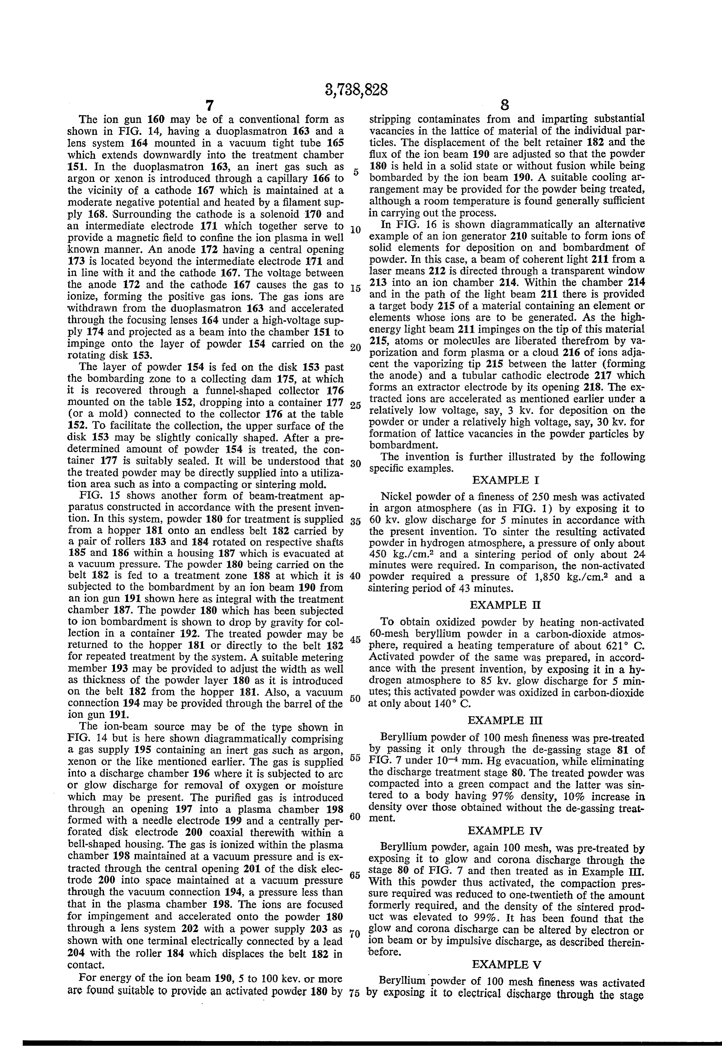
The ion gun 160 may be of a conventionalform as stripping contaminates from and imparting Substantial shown in FIG?14,havinga duoplasmatron 163 and a vacanciesinthe lattice of materialofthe individual par 1ens system 164 mounted in a vacuum tighttube 165 ticles.The displacement ofthe beltretainer182andthe which extends downwardy into the treatment chamber fuxoftheion beam190areadjusted sothatthe powder 151?In the duoplasmatron 163,an inert gas Such as 180isheldinasolid state orwithoutfusion while being argon or Xenonisintroduced through a capilary166to bombarded bytheion beam 190,ASuitable coolingar the vicinity of a cathode 167 which is maintained ata rangement maybe providedforthe powder beingtreated, moderatenegative potentialand heated byaflamentsup althougharoom temperatureisfoundgeneraly Suficient ply 168.Surroundingthe cathode isa Solenoid170 and incarryingoutthe process?
an intermediate electrode 171 which together serve to In FIG?16is shown diagrammaticaly an alternative provide a magnetic field toconfnetheion plasmainwel example ofaniongenerator210suitable toformions of known manner,An anode 172 havinga central opening solid elements for deposition on and bombardment of 173islocated beyond theintermediateelectrode171 and powder.Inthiscase,abeam of coherentlight211froma in line withitandthe cathode167.The voltage between lasermeans212isdirectedthroughatransparentwindow the anode 172 and the cathode 167 causes the gas to 213into anion chamber214,Within the chamber214 ionize,forming the positive gasions?The gasions are andin the path of the light beam 211thereis provided withdrawn from the duoplasmatron 163and accelerated atarget body215 ofa materialcontaininganelement Or through thefocusinglenses164 undera high-voltage Sup elements whose ions are to be generated?Asthe high DIy174andprojectedasa beamintothe chamber151to energylight beam211impingeson the tip ofthismaterial impinge onto the layer of powder 154 carried on the 20 215,atoms ormoleculesareliberatedtherefrom byva rotating disk153? porization and form plasma oracloud216 ofionsadja The layer of powder154isfedon the disk153 past cent the vaporizingtip215between the latter(forming the bombarding Zone to a colectingdam175,at which the anode)and a tubular cathodic electrode217 which it is recovered through a funnel-shaped colector 176 formsan extractorelectrode byits opening218.The ex mounted on thetable152,droppingintoacontainer177 25 tractedionsareacceleratedasmentionedearlier undera (Ora mold)connected to the colector176atthe table relatively low voltage,say,3 kv?for deposition on the 152?Tofacilitate the colection,the uppersurface ofthe powderorunderarelativey high voltage,Say,30 kv.for disk153 may be slightly conicaly shaped?Aftera pre formation of lattice Vacanciesin the powder particles by determined amount of powder 154istreated,the con bombardment?
The invention is furtheriustrated by the folowing tainer 177 is suitably sealed,Itwilbe understood that 30 Specific the treated powdermay bedirectlysuppliedintoautiza examples?
tionareasuchasinto a compactingorsinteringmold? EXAMPLE T FIG?15 shows another form of beam-treatmentap Nickel powder ofafnenessof250 meshwasactivated raratus constructedinaccordancewith the presentinven in argon atmosphere(as in FIG?1)by exposingitto tion·Inthissystem,powder180fortreatmentissupplied 60 kv.glow discharge for5 minutesinaccordancewith from a hopper181 onto an endess belt182carried by the presentinvention?To sinter the resulting activated apairofrolers183and184rotatedonrespectiveshafts powderin hydrogenatmosphere,apressure ofonlyabout 185and186withina housing187whichisevacuatedat 450 kg/cm°and a sintering period of only about24 a vacuum pressure.The powder180 beingcarriedon the minutes were required,In comparison,the non-activated belt 182is fed to a treatment Zone 188at whichitis 40 Powder required a pressure of 1,850 kg./cm2 and a Subjected to the bombardment byanion beam190from Sinteringperiodof43minutes?
aniongun191shown hereasintegralwith thetreatment EXAMPLE I chamber187.The powder180which has beensubjected toion bombardmentisshowntodrop bygravityforcol To obtain oxidized powder by heating non-activated lectionina container192.Thetreated powdermaybe 45 60-mesh berylium powderin a carbon-dioxide atmos ?eturned to the hopper181 ordirectyto the belt182 phere,required a heatingtemperature ofabout621°C? forrepeatedtreatment bythe System.Asuitablemetering Activated powder of the Same wasprepared,inaccord member193 may be provided toadjustthe widthaswel ance with the preSentinvention,by exposingitina hy as thickness of the powder layer180asitisintroduced drogenatmosphere to 85 kv.glow discharge for5 min On the belt182from the hopper181?Also,a vacuum 60 utesthisactivated powderwasoxidizedincarbon-doxide connection194maybeprovidedthroughthe barrelofthe atonlyabout140°C?
iongun191? EXAMPLE [[T The ion-beam Source may be of the type shown in
FIG,14butis here shown diagrammaticaly comprising Berylium powder of100meshfinenesswas pre-treated agas Supply195 containingan inertgassuch asargon, by_passingit onlythrough the de-gassingstage 81 of Xenon orthe like mentioned earlier?The gasissupplied 55 FIG.7 under10?*mm?Hgevacuation,whieeliminating intoadischarge chamber196whereitissubjectedtoarc the dischargetreatmentstage89.Thetreatedpowderwas Orglow discharge for removal of oxygen or moisture Compactedinto a green compactandthe latterwassin Which may be present?The purifed gasisintroduced tered to a body having 97% density,10% increasein through an opening 197 into a plasma chamber 198 60 density overthose obtainedwithoutthe de-gassingtreat formedwith aneedleelectrode199andacentralyper Inent?
forated disk electrode 200 coaxial therewith within a EXAMPLE TV bel-shaped housing.The gasisionizedwithinthe plasma Beyliumpowder,again100mesh,waspre-treatedby chamber198maintainedatavacuumpressureandisex exposingittoglow and corona dischargethroughthe tracted through the centralopening201 of the diskelec stäge 80 of FIG,7andthentreatedasin Example TI, trode 200 into Space maintained ata vacuum pressure 65 With thisp9wder thus activated,the compaction pres through the vacuum connection 194,a pressure lessthan Surerequiredwasreducedtoone-twentieth oftheamount thatin the plaSma chamber 198?The ionsare focused formery?quired,andthe density ofthesintered prod forimpingement and accelerated onto the powder180 Uct was elevated to 99%?It has been foundtha?the through a ens system 202with apowersupply203as &lowand corona discharge can bealteredbyelectronor shownwith oneterminalelectricalyconnected bya1ead ? beam orbyimpulsive discharge,asdescribedtherein 204 with the roHer184which displacesthe belt182in UBIOTe?
COntact? EXAMPLEV Forenergy oftheion beam190,5to100 key.ormore arefound Suitabletoprovideanactivated powder180by 75 byBerylmgowder of100 mesh finenesswasactivated exposingitto electrica dschargethroughthe Stage
Page 8
80of FIG.7andthereafterwassubjected to an electro sulfurcontent ofapetroleum oi containing4.2% sulfur static feld of150 kv.throughthe stage of FIG?9,asit can bereducedto1.2% bycontacting hydrogenatapres was packedin the mold112.The packed density of the Sure 42atm.to the oi heatedatatemperature of420° Powderwasidenticaltothatobtainedwithamechanical C.Inaccordance with the presentinvention,these metal pressof1.5tons/cm°pressure.Inanotherinstance,beryl oxide particles weretreated,with a system as shown in liumpowderofthesamemeshwas,upon the dischargeac FIG?13,bya high-energy beam ofargonionsaccelerated tivation,subjectedtoelectrostaticfield of40 kv.strength? at88 key?andwith a current of2.8miliamperes. Lat The packed density oftheloaded powderinthiscasewas tice defectswere observedinthetreated particles.When identicaltothatobtainedwith a mechanicalpress of200 these activated particles were used as catalyzer carrier kg/cm^ pressure? ?0 particles in desulfurizing an untreated oi mentioned EXAMPLEV? above,heating the oil only at312°C?and hydrogen feedat11atm?wasfound suficienttoachievethesame
For usein fueIcelsaselectrode material,400mesh Sulfurreduction?
nickelpowderwasprocessedaccordingtoFIG.11 witha EXAMPLE IX shockenergy of11.000joules,whichisaboutfour Mach? ?5
Itwasgiven threeshocksata distance oftencentimeters Titanium powder of99.3% purityand300mesh par and thensinteredinto a plate one bytwenty by twenty ticle size Wastreated usinganapparatus Hkethatshown miliametershavingadenstiyof70%. in FIG?15,whereinargon wasintroducedata pressure Three hundred mesh siver wasgiventhe same shock of 10??mm?Hginto plasmachamber198whereitwas treatmentandalsocompressed to70% denityina plate 20 Subjected to an electric discharge at160 voltsand25 one bytwenty bytwenty miliameters? miliamperesforionization.Theargonionswereextracted These plateswerethen usedinthe fuelcellof FIG,12 from the chamber198throughtheaperture201centraly with the nickelside to oxygen,the siverside to hydro formedin the diskelectrode200andaccelerated under gen,andwith potassiumhydroxideastheelectrolyte.(Cal 30 kv·andat10microamperesagainstthetitanium pow cium oxide wasused on both plates priorto theirusein 25 der180carriedonthemovingbelt182.Thevacuumpres the fuelcell,foractivation only.)An exact duplicate of Sure within the treatment chamber was maintained at the fuel celemployingsintered nickeland silver which 10?°mm?Hg?Thetreated powder,withimpartediattice weremadefrom thesame powderbut by ordinarysinter Vacanciesinindivdualparticles,waselectricalysintered ingwasalsomade and was found to produce a Voltage to a.coherent bodywhich showeda density of994%,a of0.9v.anda currentof120miliampsinthe fuelcel? 30 tensie Strength of249kg/cm°and an elongation of Underthe same conditionsthe materialactivated bythe 23%·in comparison,a body sintered underthe same shockenergyproduceda potentialof1.1 voltsanda cur conditionfromuntreated titanium powdershowed98% rentof340 milliamps? - density,165kg/cm°tensile strengthand15% elonga In addition to theinertgases namedin the examples, tion?
nitrogen,helium,neon,krypton,Xenon,andadmixturesof 35 Ions,whennot propery energized,tend tomaterialy twoormorewitheachother orwithargon orcarbon di adhereonindividualparticlesratherthanknockingonsub oxide may be used,Hydrogenisthe bestreducinggas, Strateatomsanditisfound desirable,forthepurpose of when thatis desired,especialy hot hydrogen?Reduced activation byformation oflattice vacanices,that powder pressureair,e.g,nearvacuum,can beused.Whichgasis be Subjectedto bombardment ofionsacceleratedunder bestdepends partlyonthe powderbeingtreated.Theterm 40 atleast5ky.However,suchtendencyofadherenceisad metalic powderisintended to inciude not only actual Vantageousiyfoundusefulsometimes,especialywhenions metal powders but also metal carbides,carbon,other are of Substancewhichitis desiredtoformacoatingon metalic compounds,eveninsomeinstances metaloxides, theindividualparticles?Thus,accordingtothisdiscovery nitrides,sulfides,etc.It wilbe apparent thatthe process oftheinvention,itis possibletoprepareahighlypurifed, nay be varied tosuitthe exact material;forexample,re 45 activatedpowder ofcompositeparticlestherebypreparing ducing atmospheres are desirable Sometimes and not analoyproductthroughsubsequentsintering.Tothisend, others,for example where oxides are a desired end thedischargeelectrodesystem197,198canbemadefrom Droduct? a desired materialwith which the surfaces ofindividua1 EXAMPLEVII Particles of powderaretoformaloylayersandasuitable
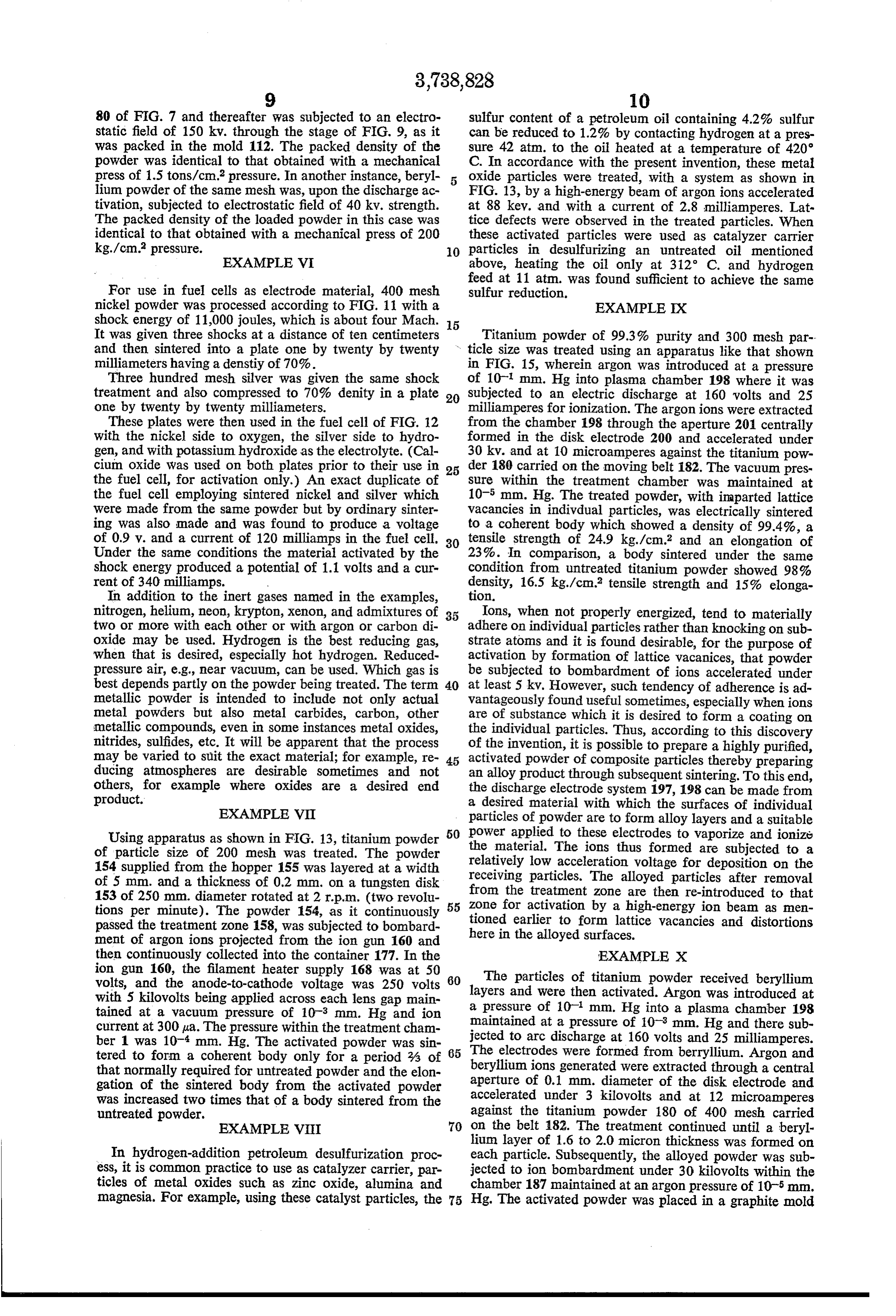
Usingapparatusasshownin FIG,13,titanium powder 50 Powerappied totheseelectrodestovaporize andionize of particle size of 200 mesh wastreated?The powder the material?Theions thus formed are subjected to a 154suppliedfromthe hopper155was1ayeredatawidth relativeylow acceleration voltage for deposition onthe of5 mm.andathickness of0.2mm?onatungstendisk receiying particles?The aloyed particles afterremoval from the treatment Zone arethen re-introduced tothat 153of250mm.diameterrotatedat2rp.m.(tworevolu 55 Zone foractivation bya high-energyion beamasmen tions per minute)?The powder 154,asit continuously tioned earierto form lattice vacanciesand distortions passedthetreatmentzone158,wassubjectedtobombard hereinthealoyedsurfaces?
ment of argonions projected from theiongun160and then continuously collectedintothe container177.Inthe EXAMPLEX ion gun 160,the fiament heater Supply168 was at 50 60 The particles of titanium powder received berylium volts,and the anode-to-cathode voltage was 250 volts with5 kiovolts beingappliedacrosseachlensgap main layersand a pressure were thenactivated.Argonwasintroducedat
tainedata vacuum pressure of10?°mm?Hgandion naintainedata pressure of10?°mm?Hgandtheresub currentat300ka.Thepressurewithinthetreatmentcham jectedtoarc dischargeat160voltsand25miliamperes? ber1 Was10??mm?Hg.Theactivated powderwassin tered to form a coherent body only fora period % of 65 The electrodeswereformedfromberrylium.Argonand thatnormalyrequiredforuntreatedpowderandtheelon beryliumionsgeneratedwereeXtractedthroughacentral gation of the sintered body from the activated powder aperture of 0.1mm?diameter ofthe diskelectrodeand wasincreasedtwotimesthatofabodysinteredfrom the accelerated under3 kilovolts andat12 microamperes untreated powder? against the titanium powder180 of 400 mesh carried EXAMPLEVIII 70 on the belt182,The treatment continued untiaberyl lium layer of1.6to2.0 micronthicknesswasformedon
In hydrogen-addition petroleum desulfurization proc each particle.Subsequenty,the aloyed powderwassub ess,itiscommon practicetouseascatalyzercarrier,par jected toion bombardment under30 kiovolts withinthe ticles of metal oxides such as Zinc oxide,alumina and chamber187maintainedatanargon pressure of10?5mm? nagnesia?For example,usingthese catalyst particles,the 75 Hg,Theactivatedpowderwasplacedinagraphitemold
Page 9
and electricaly sintered by receiving the passage of an 7,The method of claim6Wherein the metalic oxide electric current therethrough betweena pair ofgraphite particles are chosen from the group consisting of the electrodesand under pressures,initialy6kg/cm°and oxides of aluminum,magnesium,and Zinc? finaly 500 kg/cm°,The required electric power and 8.The method of claim 6 wherein argon ions are Sintering periodwere only121kilowattsandsix(6)sec 5 usedasthe high-energyions?
onds,respectively.The density ofthe sinteredarticlewas 9.The method of claim 8 wherein the argon ions 98%?In comparison,untreated titanium and berylium are accelerated atabout 88 keV?and with a current of powders were mixed by convetionalprocedure requiring about2.8miamperes?
considerable lapse of time and,asthey were uniformly 10,Aprocess ofactivatingmetalic powderinaman Tnixed,the mixture Was electricaly sintered under the nertoimproveitspurityand density,comprising ; Same conditions as used for the activated powder?The continuously Supplyingmetalic powdertoatreatment resultantsintered bodywas of only85% densityandthe ZOne, required powerandsinteringperiodwas160kilowattsand bombardingthe powderin said treatment Zone andin 40seconds,respectively? a non-oxidizing vacuum atmosphere ata pressure To those skiled in the art to which this invention 15 below 0.01mm?Hgwith high energyionsatamin relates,manychangesin constructionandwidelydifering imum of5 kev.
embodiments andapplications oftheinvention wilsug 11,The method of claim 10wherein the bombarding gestthemselveswithoutdepartingfromthespiritandscope Step comprises moving the powder through a beam of oftheinvention.The disclosuresandthe description here Saidionsata controlled speed? inarepurelyilustrativeandarenotintendedto beinany 20 12,A process of aloying metalic powder while ac Sense limiting, tivatingit,comprising
I claim: continuousy Supplying a metalic powder of a frst 1.Aprocess of packingmetalic powderina moldina metaltoatreatmentzone, manner to improve its purity and density,comprising bombardingthe powderin Saidtreatmentzoneandin continuousiy Suppying metalic powderto a purifica 25 a non-oxidizingatmosphere with high energy ions tion Zone, of a Second metalandions ofaninertgas,atan bombardingthe powderinafuidizedstateinsaid puri energy below 5 kev,to enable adherence of said fication Zoneandinanon-oxidizingatmospherewith Second metalionsto Said frstmetalparticles,until highenergyparticleschosenfromthe classconsisting a desiredthicknessof said secondmetaiisobtained? of Sub-atomic particles,ions,and molecules, 30 13.The process of claim12wherein the treatmentis continuouslyseparatingfrom the powdertheimpurities folowed bythen bombardingtheresultantparticleswith thatare cleanedfrom theparticle surfaces duringthe ions ofgas alone atan energy wel1above 5 kev? bombardingstep,and 14,The proceSS of claim13wherein the bombarding continuouslydroppingsaidmaterialform Saidseparating Stepisfolowed by sinteringthemetalparticles. 15,The process of claim 12 wherein said frstmetal
Stepintoa moldand compactingitthere? 35 istitaniumand Said second metalis berylium, 2?The process of claim1Wherein the bombardingstep 16,The processof claim15whereinsaiddesiredthick comprises positioning the powder in its fuidized state nessis1.6to2.0 microns?
betweena pairofelectrodesandapplyingacrosssaidelec trodesa high-amperagedirectcurrentandalow-amperage 40 References Cited alternatingcurrent to promote high-frequency discharge amongthe particles, UNTTED STATESPATENTS 3.The process of claim1 whereina second bombard 3,464,790 9/1969 Schraderetal??? 204?157.1 nentstepiscarried on duringthe droppingstep. 3.355279 11/1967 Ishibashi ????????????? 75?5 4?The process of claim 1 wherein the treatmentin 45 3.485,771 12/1969 Horvath ??????????? 252?410 cludes applyinga magnetic force atsubstantially right 3.247.014 4/1966 Goldbergeretal.???? 204?164 angestothe?aththepowderfolowswhileitisdropping 3,104216 9/1963 Ruskin ??????????? 204?157.1 intosaid mold? 3,105,024 9/1963 Schutze etal,????? 204?157.1 5,The process of claim 1 wherein the powder is 3.537.966 11/1970 Steinbergetal,????? 204?157.1 bombarded bya beam ofelectronsafteritisinsaidmold, 6?A method of activating metalic oxide catalyzer CARLD.QUARFORTH,PrimaryExaminer carrier particlestoimprove theircataiytic action,com B.HUNT,Assistant Examiner
Drising projecting a beam of high-energyions from anion U.S.Cl?XR,
bombardingthe particlesina vacuum ofatleast0.01 75?5R;134?1;204?164;209—3,22;252?461,463, mm?Hg with the high-energy beam ofions, 475?
Provenance
- Collection
- Cited prior art
- Original PDF
- patentimages.storage.googleapis.com →
- Filed
- 1970-07-31
- Pages
- 9
- Method
- pdftotext (the PDF's own text layer) + pdftoppm 300dpi page scans
- Source
- Google Patents bibliographic record
- Granted
- 1973-06-12
- Inventors
- K Inoue
- Transcribed from
- patentimages.storage.googleapis.com →