patent · US3903913
Method for charging a chamber with high pressure fluid
9 September 1975
Page 1 — bibliographic record
United States Patent (19) 3,903,913 Umphenour et al. (45) Sept. 9, 1975 54 METHOD FOR CHARGING A CHAMBER 3,074,433 fl63 Stark............................... 25A282 X WITH HIGH PRESSURE FLUID 3,684.238 8/1972 Michellone et al............. 25 1/282 X 75 Inventors: Charles F. Umphenour; Reynaldo
Calderon, both of Houston, Tex. Prinary Examiner-Martin P. Schwadron
Assistant Examiner-Robert J. Miller 73) Assignee: Texaco Inc., New York, N.Y. Attorney, Agent, or Firm-T. H. Whaley; C. G. Ries; 22 Filed: an. 28, 1974 Theron H. Nichols
Related U.S. Application Data 57 ABSTRACT
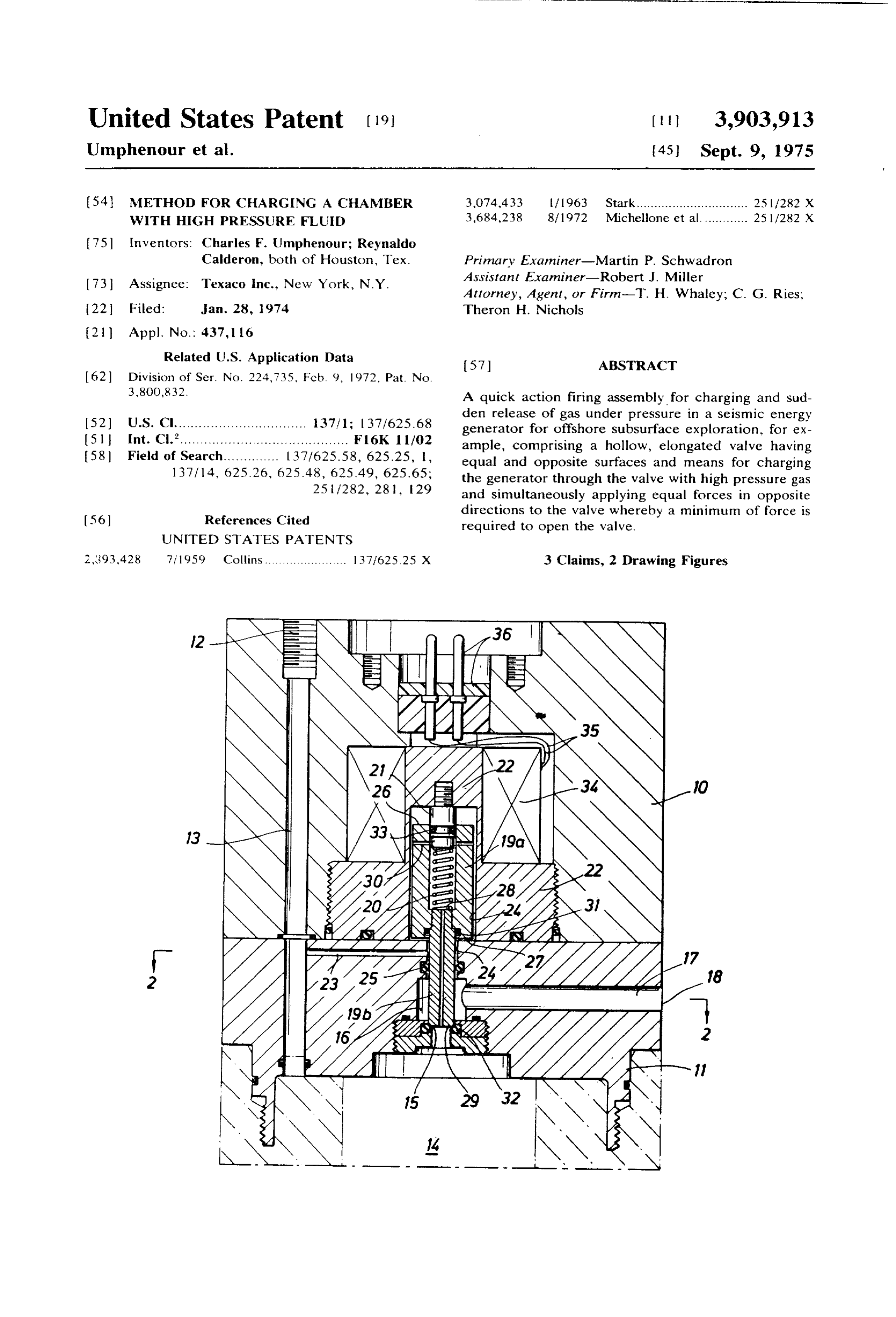
3,800,832. A quick action firing assembly for charging and sud den release of gas under pressure in a seismic energy 52 U.S. Cl................................. 137/1; 37/625.68 generator for offshore subsurface exploration, for ex (51 Int. Cl.’.......................................... F16K 1 1/02 ample, comprising a hollow, elongated valve having 58) Field of Search.............. 137/625.58, 625.25, , equal and opposite surfaces and means for charging 137/14, 625-26, 62.5.48, 625.49, 625.65; the generator through the valve with high pressure gas 25 7282, 28, 29 and simultaneously applying equal forces in opposite
directions to the valve whereby a minimum of force is required to open the valve.
UNITED STAES PATENTS
2,393.428 7, 1959 Collins ....................... 1371625.25 X 3 Claims, 2 Drawing Figures
NNR
Page 2
Drawing sheet — no readable text.
Page 3
METHOD FOR CHARGENG A CHAMBER WITH sparks to ionize a portion of the water surrounding the HGH PRESSURE FLUID electrode, or suddenly releasing a container of high This is a division, of application Ser. No. 224,735, pressure air underwater for generating a large seismic filed Feb. 9, 1972, now U.S. Pat. No. 3,800,832. or pressure wave signal. These seismic signals are re BACKGROUND OF THE INVENTION flected from subsurface geological formations and structures and are received by seismometers and re
Broadly the present invention relates to seismic ex corded.
ploration and to an improved pneumatic marine seis In all methods utilized, it is customary to tow one or mic energy source for the introduction of seismic en more detectors through the water in the vicinity of the ergy into water from a floating vessel for supplying O sound source to detect the signals that are reflected compressed air and having a geophysical crew thereon from the various subsurface formations and structures. for exploring earth layers and formations underlying The detected signals are recorded on suitable equip bodies of water as oceans, seas, lakes, rivers, or the ment contained on the towing vessels, either in the like. More particularly this invention pertains to a form of analog or digital signals. Also, at times the sig method and at least one mechanism for carrying out 15 nals are recorded as variable area signals to provide a the method, one exemplary mechanism being a quick profile of the surveyed area. The latter recording is sim action firing assembly for efficiently charging a seismic ilar to those contained with conventional depth energy generator chamber with a high pressure gas and sounding equipment.
likewise for quickly and efficiently releasing the high All of the above seismic methods and devices have pressure gas from the chamber with an expenditure of 20 various disadvantages and thus none is completely suit a minimum of energy or force. able for use in all circumstances. The handling of an ex While the method and apparatus of the invention are plosive material is, of course, dangerous as mentioned applicable for many purposes as will be set forth further previously, wherein the explosions themselves tend to below, they are illustratively disclosed and described as kill much marine life, an example of a seismic explosive applied to underwater sound instrumentation such as 25 device being disclosed in U.S. Pat. No. 2,877,859. oceanographic equipment and systems that are em Also, in the case of dynamite two separate vessels are pioyed in seismic exploration of the world's crust under required; one for handling the dynamite and the other and adjacent to bodies of water. for the recording equipment. This, of course, increases Since water is such a good sound conductor, it is un the cost of the survey.
necessary to generate sound waves right on or in the 30
Aside from the operational advantages over conven ocean floor; they can be produced in the water near the tional surface. The pressure waves travel down through the better dynamite data surveys, the disclosed system affords acquisition through the effective and water to the ocean floor and are reflected as in the quicker acting pressure release valve having less back usual echo-sounding techniques. However, these waves pressure to work against and requiring less power or
also penetrate into the ocean floor and are reflected voltage to actuate the actuating solenoid for firing a from the sub-strata. These acoustical waves also propa seismic acoustical energy generator or air gun. gate horizontally through one or more geological strata The use of explosive gas mixture solves some of the and may be recorded at a distance from the source, problems that arise with dynamite, since explosive gas thus providing useful refraction data on the stratum or mixtures do not kill as much marine life, a further ex
ample being disclosed
Although explosives for marine seismic work can put mally, gas mixtures can in U.S. Pat. No. 3,620,327. Nor large amounts of energy into the water and obtain great explosive gases on the samebevessel stored as separate, non depth of penetration, they do have drawbacks; they are cording equipment. Thus, the needthatforcontains an the re additional dangerous to handle and use, and in some areas such vessel or the possibility of killing marine life is reduced. as congested harbors, they cannot be used at all. Also, 45 While one disadvantage of gas type sound sources is the each 'shot' is very expensive and can run into many relatively short life of the flexible container or sleeve in thousands of dollars per survey. Explosives tend gener ally to concentrate substantial amounts of their energy which theofexplosive gas mixtures are detonated, con output into higher frequency components which may Servation the cipal problems. present environment is one of the prin not be desirable for many purposes; whereas, the sound 50 impulse generation method and apparatus which the it has in Sound sources employing an electrical discharge, present invention is used on can be adjusted over a charged been customary to discharge a bank of capacitors large amplitude range and adjusted in frequency so as multiple to a high voltage through a single electrode or parallel electrodes and a ground plate. When to provide the desired spectrum distribution of sound 55 the capacitor bank is discharged into the water by the frequencies for the purpose at hand.
The present invention is illustratively described as duced at each electrodeplate electrodes and ground tip, the pressure bubble is pro for the ground plate serves embodied in a device capable of emitting a large as a return for the electrical energy. The pressure bub amount of acoustical energy into water in the form of ble produces the desired seismic impulse a clear, repeatable pulse, the frequency and amplitude ground adds nothing to the magnitude of thewhile the of which may be readily averred. These powerful sound acoustical wave. In fact, only 3–5 percent of outgoing the total impulses are well adapted for use in seismic exploration systems and also can be used to advantage for other electrical energy available in the capacitor bank is con purposes. verted to useful acoustical energy in the water. Further, Seismic surveys which are conducted over water cov many Spark electrodes in parallel may be used simulta ered areas use various methods for generating seismic 65 neously as disclosed in U.S. Pat. No. 3,613,823. energy as by the detonating of conventional powder or DESCRIPTION OF PRIOR ART dynamite, or gas mictures, electrical discharge of While compressed pneumatic guns as disclosed in
Page 4
application Ser, No. 160,693, filed July 8, 1971, each DESCRIPTION OF THE PREFERRED METHOD OF
THE INVENTION
has a passage through the plunger for the passage of air, none have the feature of equal and opposite areas nor The invention disclosed herein, the scope of which mal to the longitudinal axis of the plunger for insuring S being defined in the appended claims, is not limited in a minimum required force to actuate the plunger to re its application to the details of construction and ar rangement of parts shown and described for carrying lease the compressed air. The most pertinent disclo out the method, since the invention is capable of other sure, assignees' above identified application, illustrates embodiments an air gun in which a larger area and resultant force O being practicedfororcarrying carried out other methods and of out in various other ways.
tending to maintain the plunger closed, in addition to Also, it is to be understood that the phraseology or ter the spring, must be overcome to open the valve, minology employed herein is for the purpose of de whereas the instant invention has only the force of the scription and not of limitation, Further, many modifica spring to overcome, resulting in a much faster operat tions and variations of the invention as hereinbefore set ing seismic energy generator requiring less power or 15 forth may occur to those skilled in the art. Therefore, voltage to operate the solenoid for actuation of the all such modifications and variations which are within valve. the spirit and scope of the invention herein are in OBJECTS OF THE INVENTION cluded and only such limitations should be imposed as are indicated in the appended claims.
A primary object of this invention is to provide a This invention comprises both a method and a device method for charging a chamber with high pressure fluid for carrying out the method of charging a chamber with and for quickly releasing the fluid with a minimum high pressure gas and for quickly releasing the gas with force. a minimum force.
Another primary object of this invention is to provide This method comprises the steps of: a device for carrying out the above method comprising 25 1. charging the chamber with high pressure fluid a valve assembly for charging a chamber with high through a hollow closed valve, and pressure fluid and simultaneously applying equal and 2. simultaneously applying equal forces in opposite opposite forces to the valve for requiring a minimum of directions to the valve so that only a minimum of valve opening forces. force is required to open the valve for quick release of the fluid.
Another object of this invention is to provide a hol Step 2 comprises in greater detail: low, spring loaded valve for supplying gas under pres 1. applying fluid under pressure to equal areas of the sure to a chamber and a means for applying an equal valve in opposite directions simultaneously with force in both directions to the valve whereby a mini charging of the chamber. mum force is required to open the valve. 35 Modifying the second method step or adding a third A further object of this invention is to provide a valve method step comprises:
having equal and opposite areas and means for apply a. cutting off flow of high pressure fluid to the cham ing a fluid pressure for developing equal and opposite ber simultaneously with applying equal forces in forces on the valve so that a minimum force is required opposite directions to the valve whereby only a
minimum force is required to open the valve.
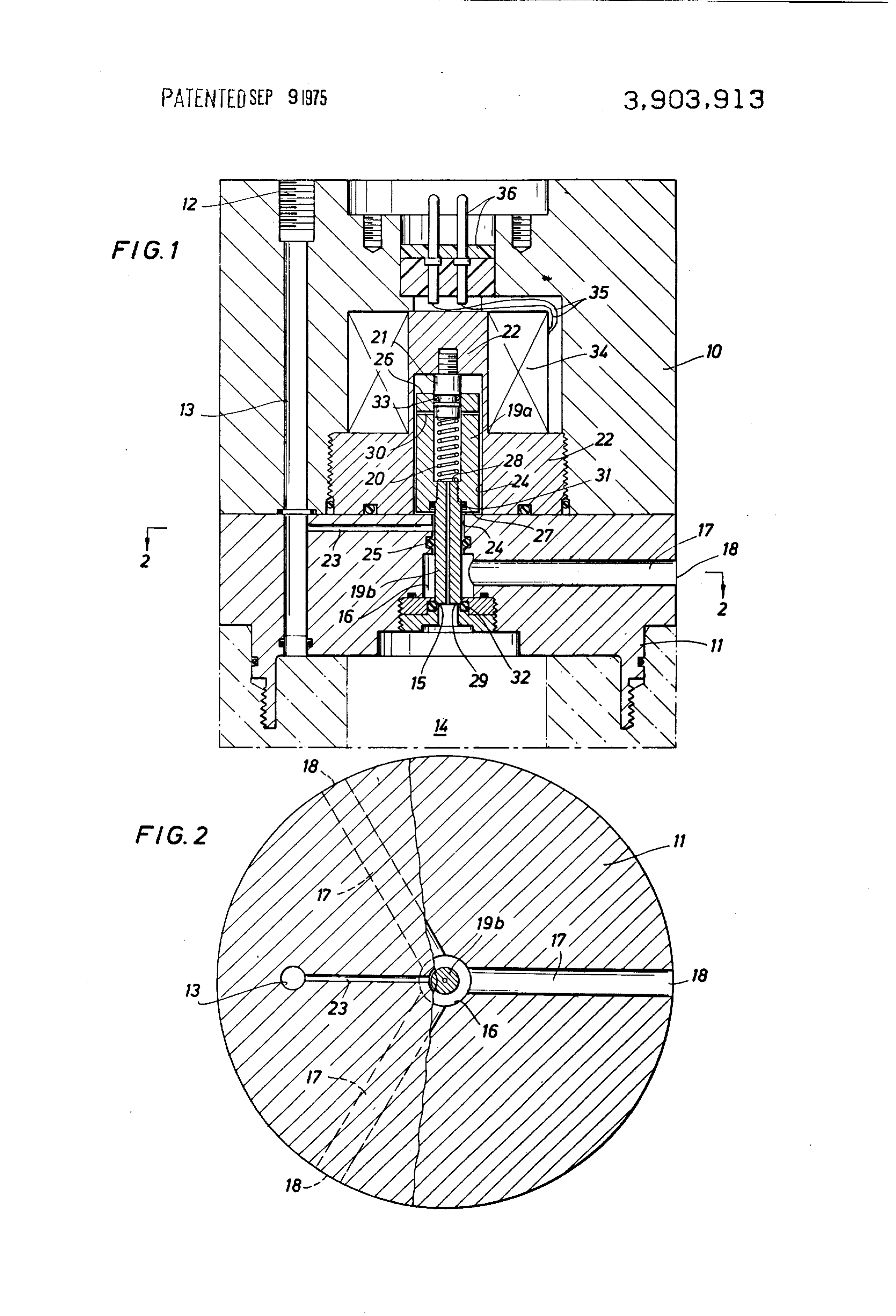
Still another object of this invention is to provide an DESCRIPTION OF THE PREFERRED air gun firing assembly for a seismic energy source EMBODIMENT which is easy to operate, is of simple configuration, is economical to build and assemble, and is of greater ef 45 While various articles may be utilized for carrying ficiency for charging a seismic energy generator and for out the above method of the invention, the preferred suddenly releasing the gas under high pressure for off embodiment comprises a quick-action valve assembly shore subsurface exploration. for sudden release of gas under pressure from an inlet Other objects and various advantages of the disclosed exit port of a chamber of a seismic acoustical energy firing assembly for an acoustical energy generator for SO generator. Likewise, this valve assembly is utilized also offshore subsurface exploration will be apparent from for charging the high pressure chamber. the following detailed description, together with ac The disclosed firing assembly comprises, as shown in FIG.
companying drawing, submitted for purposes of illus ing assembly1, a cylindrical housing 10 for containing the fir tration only and not intended to define the scope of the and for attaching to a conventional acous tical pneumatic energy generator 11.
invention, reference being had for that purpose to the 55 A typical seismic wave generator 11, FIG. 1, is low subjoined claims. ered into the surrounding earth, marsh, or water, off BRIEF DESCRIPTION OF THE DRAWING shore or down in a conventional shot hole filled with water, for example. Accordingly, the generator is illus
The drawing diagrammatically illustrates by way of trated laying on its side in FIG. 1 with the top portion example, not by way of limitation, one form of the in 60 to the left, for clarity of disclosure. While FIG. 1 illus vention wherein like reference numerals have been em trates the position of the seismic energy generator in ployed to indicate similar parts in the several views in the vertical position for shothole seismic surveying which: when being towed for offshore subsurface exploration, F.G. 1 is a schematic sectional view of an embodi 65 the generator would be rotated clockwise 90. ment of the new seismic energy generator having the The circular housing 10, FIG. 1, has an inlet 12 at the new firing mechanism therein; and top connected to a suitable source of high pressure FIG. 2 is a sectional view at 2-2 on F.G. . fluid, such as air, which is supplied to main passage 13
Page 5
for distribution to the air gun 11, and particularly to a solenoid has to overcome only the force of the spring high pressure air chamber (not shown) at the bottom of the air gun and to a firing mechanism at the top of to actuate plunger valve 19 to open chamber inlet-exit port 15, the friction and drag of the air passing through the air gun. the passages being negligible, The air gun has a smaller chamber 14 having an inlet 5 exit port or opening 15, outlet passages 16 and 17, and theFIG. 2, a sectional view of 2-2 on FIG, , illustrates exhaust port 18 from which the expanding air rushes haust ports, 17 of requirement three sets of outlet passages and ex and 18, respectively, while only one out to the surrounding water, The chamber inlet-exit transverse high pressure fluid passage 23 is required. port 15 is shown closed by the new hollow plunger Thus in operation, as high pressure fluid passes valve 19. O through the main passage 13 to charge the high pres The hollow plunger valve 19 comprises two parts, a sure chamber of the air gun, this high pressure fluid or larger hollow body upper part 19a for enclosing a air spring 20 and a smaller hollow lower part or plunger versealso simultaneously passes through the first trans passage 23 and from there it flows to the second stem 19b screwed into the plunger body. The body 19a passage 24, and continues on through the third pas of the plunger is slidable over a stud 21 screwed in 15 sages plunger valve guide 22 in housing 10. Thus, when the tion of the plunger valve.intoFrom 30 of the plunger the internal or hollow por here the high pressure plunger valve is moved upwardly and opened, the high air flows the length of the plunger valve through cham pressure air may escape from chamber 14 out through exhaust passages 16 and 17 to exit from the exhaust berIt may inlet-exit port 15 to further charge the chamber, be noted that the force of the spring is the only port 18 to escape out into the surrounding water. As shown in FIG. 2, three sets of exhaust passages are pref means required and utilized for holding and maintain erable, the hollow plunger is shown closing the opening ing the plunger valve against the opening and for seal and is held in closed position with the spring 20. ing the opening. With the plunger in this position, ei High pressure air from the supply passage 13 likewise ther equal hydraulic or pneumatic pressure is applied travels transversely through a firing assembly first pas 25 to both opposite ends of both plunger valve parts and sage 23 to a annular second passage 24 around the por accordingly equal and opposite forces are applied tiun 19b of the plunger. While a sloppy fit is shown be thereto, which counteracting forces maintaining tween the cylindrical portion 19b and the walls of the plunger at either of its positions. To fire the air gun, the passage 24, FIG. 1, leakage of the air downwardly and solenoid is energized which then jerks with a minimum outwardly to outlet passages 16 and 17 is prevented by 30 of force the plunger upwardly and away from the inlet sealing O-ring 25 in the housing. From there the air exit port 15. The action of the solenoid is only opposed travels through a larger portion of the annular second by the spring in that immediately upon upward actua passage 24 surrounding the plunger larger portion 19a. tion of the plunger the third passages are closed by O Both upper and lower flat ends 26 and 27, respectively, ring 33, thereby cancelling out or stopping the flow of of the larger portion 19a of the plunger and the flat 35 high pressure fluid through the center of the plunger ends 28 and 29, respectively, of the smaller portion 19b and the pneumatic pressure maintains equal and oppo are formed to the same identical areas, respectively, site forces on the ends of the plunger valve. Accord and are normal to the longitudinal axis of the plunger. ingly, upon actuation of the plunger upwardly the high Thus, as the air under pressure passes through the an pressure fluid from the chamber is allowed to rush out nular passage 24 around the smaller and larger portions 40 of the opening 15 through the exhaust passages 16 and of the plunger, and since these air passages are formed 17 and out the exhaust port 18 to the surrounding with a sloppy fit, as illustrated in FIG. 1, resulting in water for triggering the attached air gun for generating negligible air resistance, the air correspondingly arrives the acoustical seismic sound wave for subsurface explo at both ends of each of the two valve portions 19a and 45 ration. When the plunger is at either of its end posi 19b practically simultaneously and accordingly the tions, and pneumatic forces are equalized due to being forces are neutralized for actuating the plunger in ei applied to both ends of the plunger, a minimum of ther direction. Third passages 30 extend from this sec force is required to open the plunger valve. Thus a high ond cylindrical passage 24 to the interior of the hollow pressure air supply and quick-action valve assembly is plunger valve 19. From the hollow portion of the disclosed for charging a chamber having an inlet-exit plunger the air passes to the chamber for charging it 50 port and for suddenly exhausting the high pressure air with high pressure air. Respective O-rings 31 and 32 for therefrom.
Sealing are provided between the two portions 19a and Accordingly, it will be seen that the present firing as 19b of the plunger valve and in the air gun around the sembly for the seismic energy source for off-shore sub inlet-exit opening 15 of the chamber, respectively. 55 surface exploration operates in a manner which meets A solenoid 34 is mounted in the housing around at each of the objects set forth hereinbefore. least a portion of the plunger and has electrical wires While only one method and one embodiment for car 35 passing to electrical plug 36 for plugging into a suit rying out the method of the invention have been dis able energy source for energizing the solenoid. Further, closed, it will be evident that various other methods an O-ring 33 is mounted around the end of the stud that and modifications are possible in the arrangement and protrudes into the plunger. Upon actuation of the sole construction of the disclosed firing assembly for a seis noid 34, the plunger 19a is moved upwardly in plunger mic energy generator for offshore subsurface explora 22, the spring 20 is compressed, and the plunger third tion without departing from the scope of the invention, passages 30 are sealed closed by the stud O-ring 33. and it is accordingly desired to comprehend within the When these latter passages are closed, no fluid is al lowed to flow internally of the plunger nor to pass out 65 purview of this invention such modifications as may be of the plunger to charge the attached air gun. With claims. to fall within the scope of the appended considered equal pressure on equal and opposite plunger ends, the We claim:
Page 6
1. A method for charging a chamber with high pres- a. passing the high pressure fluid into one end of the sure fluid and for quickly releasing the fluid with a min- hollow elongated plunger valve through transverse imum force comprises the steps of, passages therein, and a. plugging an opening in one side of the high pres- b. passing the high pressure fluid longitudinally sure fluid chamber with one end of a hollow elon- 5 through the rest of the hollow eleongated plunger gated plunger valve, valve to the other end thereof, and b. charging the chamber with high pressure fluid lon c. passing the high pressure fluid from the other end gitudinally through the center of the hollow elon of the elongated plunger valve directly into the gated closed plunger valve, opening in the side of the high pressure fluid cham c. retracting the hollow plunger valve from w the side 10 ber.
of the high pressure fluid chamber for quick release - of the high pressure fluid from the opening in the 3. A method as recited in claim 1 wherein the fourth side of the chamber, and method step comprises, d. maintaining substantially no fluid flow through the a. blocking the opening in the other end of the hollow hollow plunger valve during the quick release of 15 elongated plunger valve to accordingly maintain the high pressure fluid. substantially no fluid flow through the valve during 2. A method as recited in claim 1 herein the second the quick release of the high pressure fluid. method step comprises, sk k 2 k k
Provenance
- Collection
- Cited prior art
- Original PDF
- patentimages.storage.googleapis.com →
- Filed
- 1974-01-28
- Pages
- 6
- Method
- pdftotext (the PDF's own text layer) + pdftoppm 300dpi page scans
- Source
- Google Patents bibliographic record
- Granted
- 1975-09-09
- Inventors
- Charles F Umphenour; Reynaldo Calderon; Texaco Inc
- Transcribed from
- patentimages.storage.googleapis.com →