patent · US5005553
Ventilation system for automotive engine
9 April 1991
Page 1 — bibliographic record
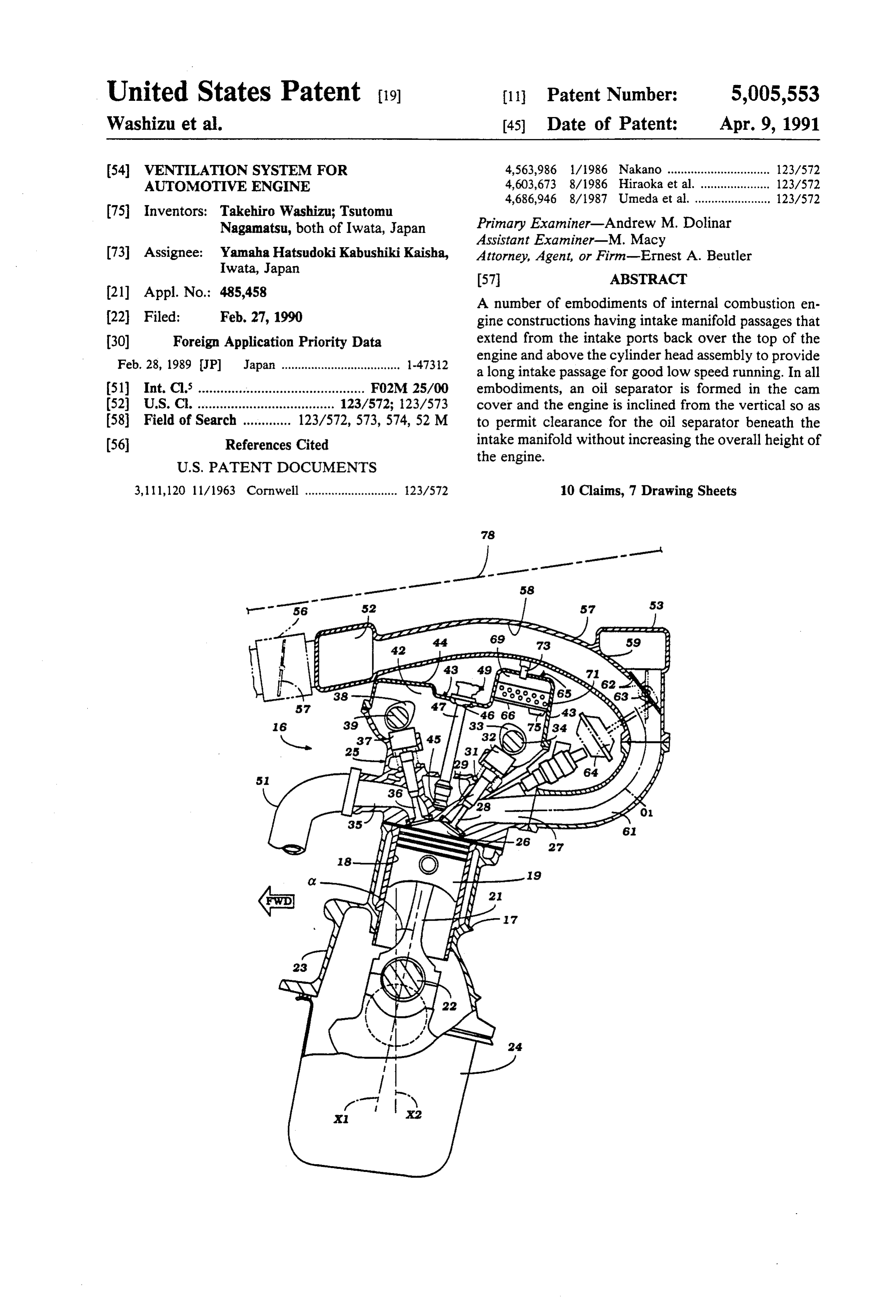
United States Patent (19) 11 Patent Number: 5,005,553 Washizu et al. (45) Date of Patent: Apr. 9, 1991 (54) VENTILATION SYSTEM FOR 4,563,986 l/1986 Nakano ............................... 123/572 AUTOMOTIVE ENGINE 4,603,673 8/1986 Hiraoka et al. ... ... 123/572 4,686,946 8/1987 Umeda et al. ....................... 123/572 75 Inventors: Takehiro Washizu; Tsutomu
Nagamatsu, both of Iwata, Japan Primary Examiner-Andrew M. Dolinar
Assistant Examiner-M. Macy 73 Assignee: Yamaha Hatsudoki Kabushiki Kaisha, Attorney, Agent, or Firm-Ernest A. Beutler Iwata, Japan
21 Appl. No.: 485,458 A number of embodiments of internal combustion en 22 Filed: Feb. 27, 1990 gine constructions having intake manifold passages that 30 Foreign Application Priority Data extend from the intake ports back over the top of the Feb. 28, 1989 JP Japan .................................... 1-4732 engine and above the cylinder head assembly to provide a long intake passage for good low speed running. In all 51) Int. Cli............................................. F02M 25/00 embodiments, an oil separator is formed in the cam 52 U.S.C. ..................................... 123/572; 123/573 cover and the engine is inclined from the vertical so as 58 Field of Search ............. 123/572, 573, 574, 52 M to permit clearance for the oil separator beneath the 56 References Cited intake manifold without increasing the overall height of the engine.
3,111,120 1 1/1963 Cornwell ............................ 123/572 10 Claims, 7 Drawing Sheets
Page 2
Drawing sheet — no readable text.
Page 3
Drawing sheet — no readable text.
Page 4
Drawing sheet — no readable text.
Page 5
Drawing sheet — no readable text.
Page 6
Drawing sheet — no readable text.
Page 7
Drawing sheet — no readable text.
Page 8
Drawing sheet — no readable text.
Page 9
der bore. A crankcase ventilating oil separator is affixed
VENTILATION SYSTEM FOR AUTOMOTIVE to the cylinder head assembly and protrudes at least in ENGINE part upwardly therefrom. An intake port is formed in one side of the cylinder head assembly to supply a
BACKGROUND OF THE INVENTION 5 charge to the cylinder bore. An intake manifold extends This invention relates to a ventilation system for an from the intake port and across the cylinder head assem automotive engine and more particularly to an in bly toward the other side thereof and above the crank proved engine arrangement that permits the use of a case ventilation oil separator. In accordance with the tuned induction system and a conveniently positioned 10 invention, the cylinder block is disposed with the axis of crankcase ventilation system and oil separator therefor. its cylinder bore inclined from the vertical for increas As is well known, the induction system for an internal ing the distance between the crankcase ventilation oil combustion engine is very important in determining the separator and the intake manifold without increasing performance of the engine. Recently it has been ac the height of the engine.
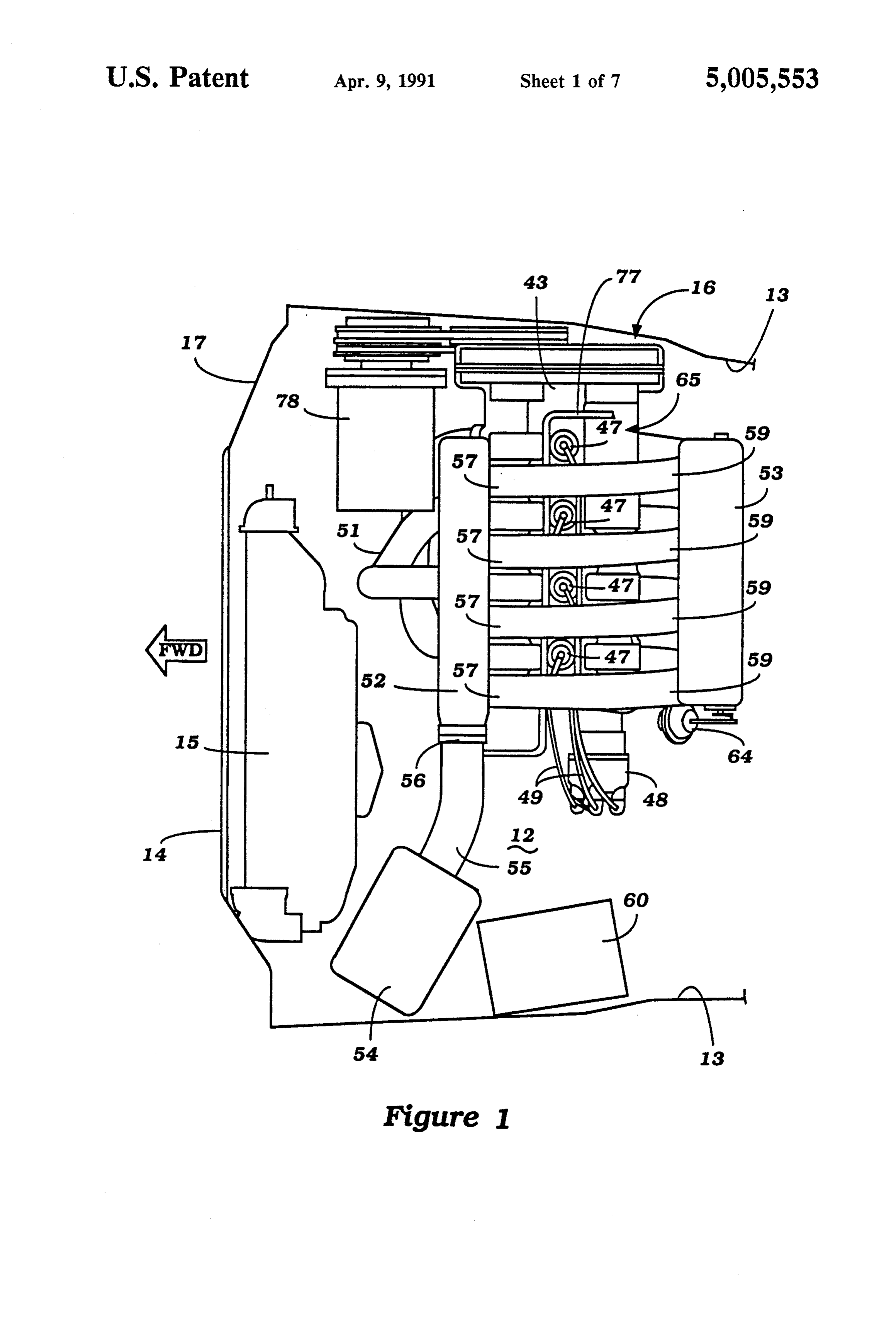
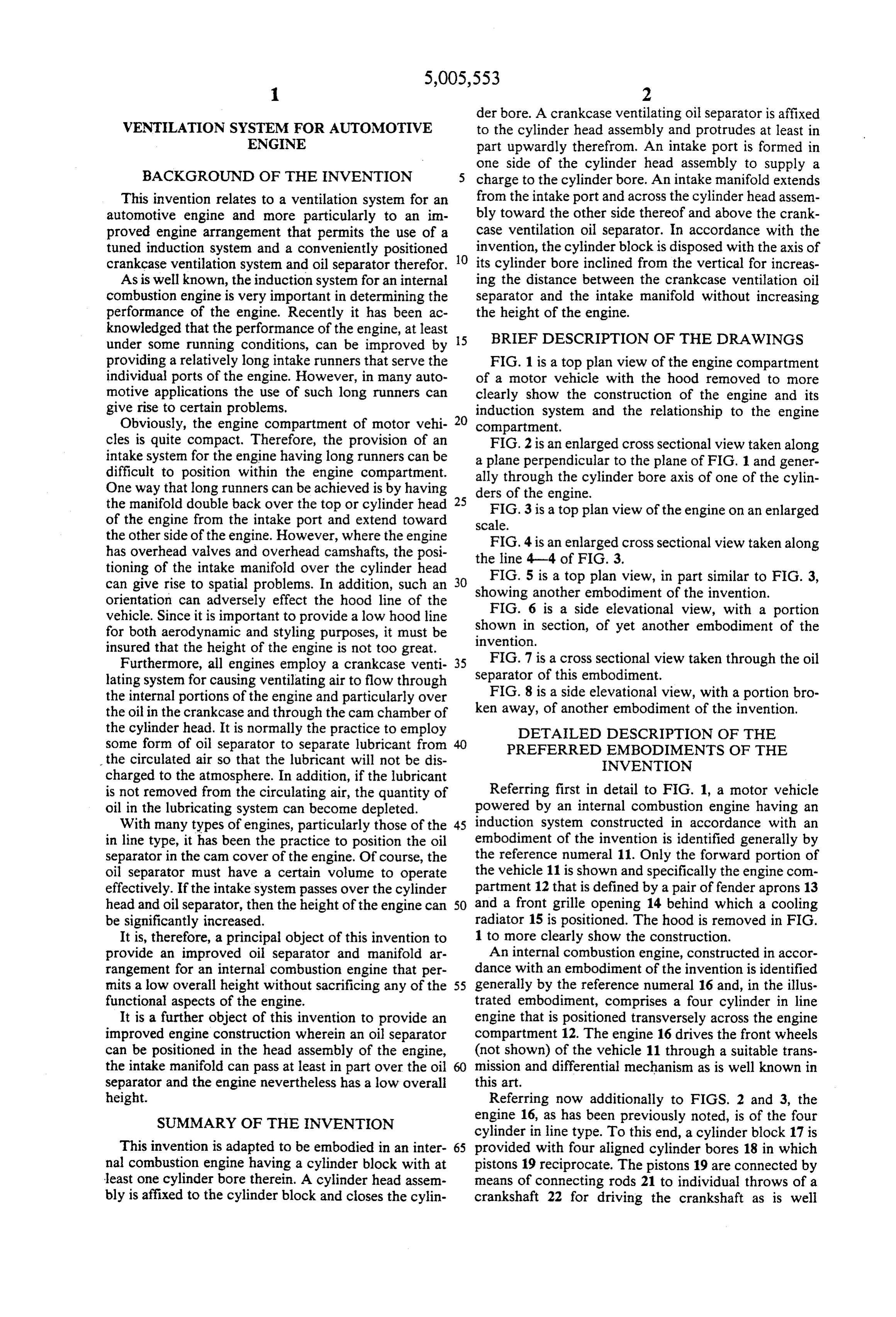
knowledged that the performance of the engine, at least under some running conditions, can be improved by 15 BRIEF DESCRIPTION OF THE DRAWINGS providing a relatively long intake runners that serve the FIG. 1 is a top plan view of the engine compartment individual ports of the engine. However, in many auto of a motor vehicle with the hood removed to more motive applications the use of such long runners can clearly show the construction of the engine and its give rise to certain problems. induction system and the relationship to the engine Obviously, the engine compartment of motor vehi 20 compartment.
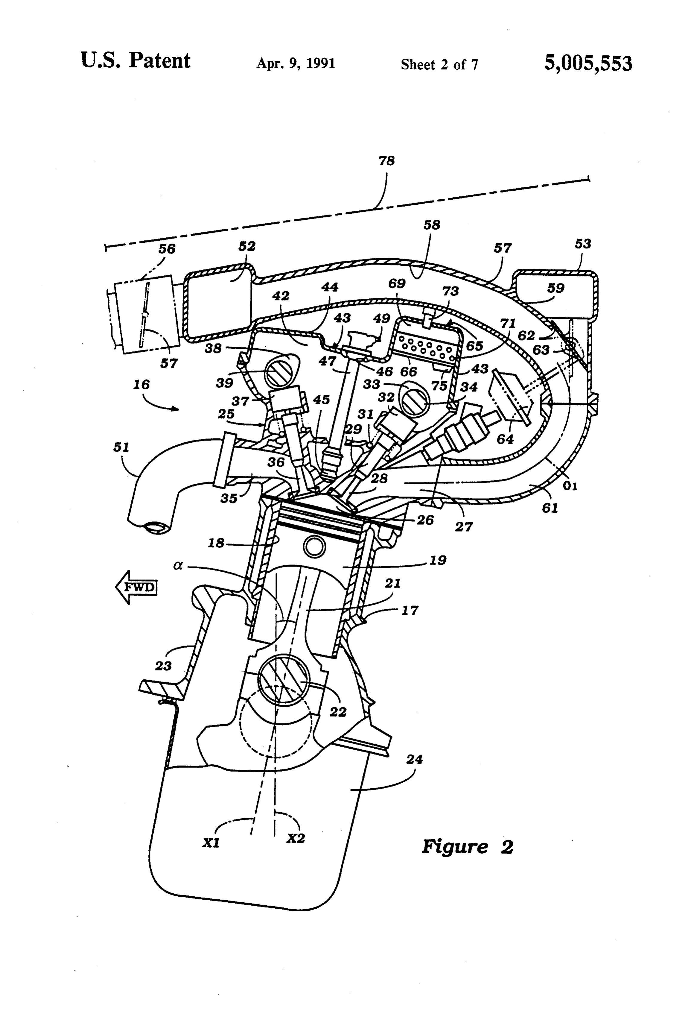
cles is quite compact. Therefore, the provision of an FIG. 2 is an enlarged cross sectional view taken along intake systern for the engine having long runners can be a plane perpendicular to the plane of FIG. 1 and gener difficult to position within the engine compartment. ally through the cylinder bore axis of one of the cylin One way that long runners can be achieved is by having ders of the engine.
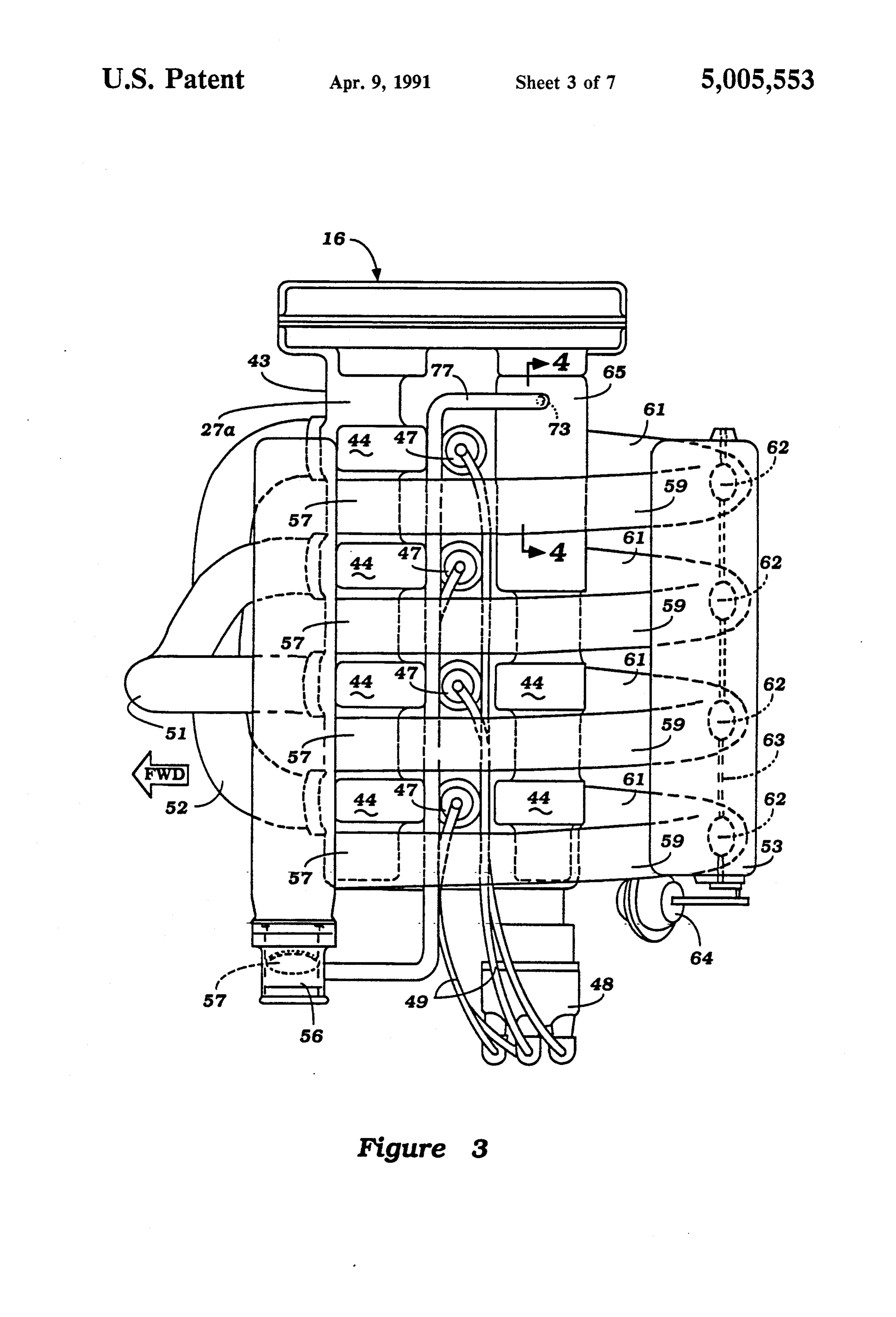
the manifold double back over the top or cylinder head 25 FIG. 3 is a top plan view of the engine on an enlarged of the engine from the intake port and extend toward scale.
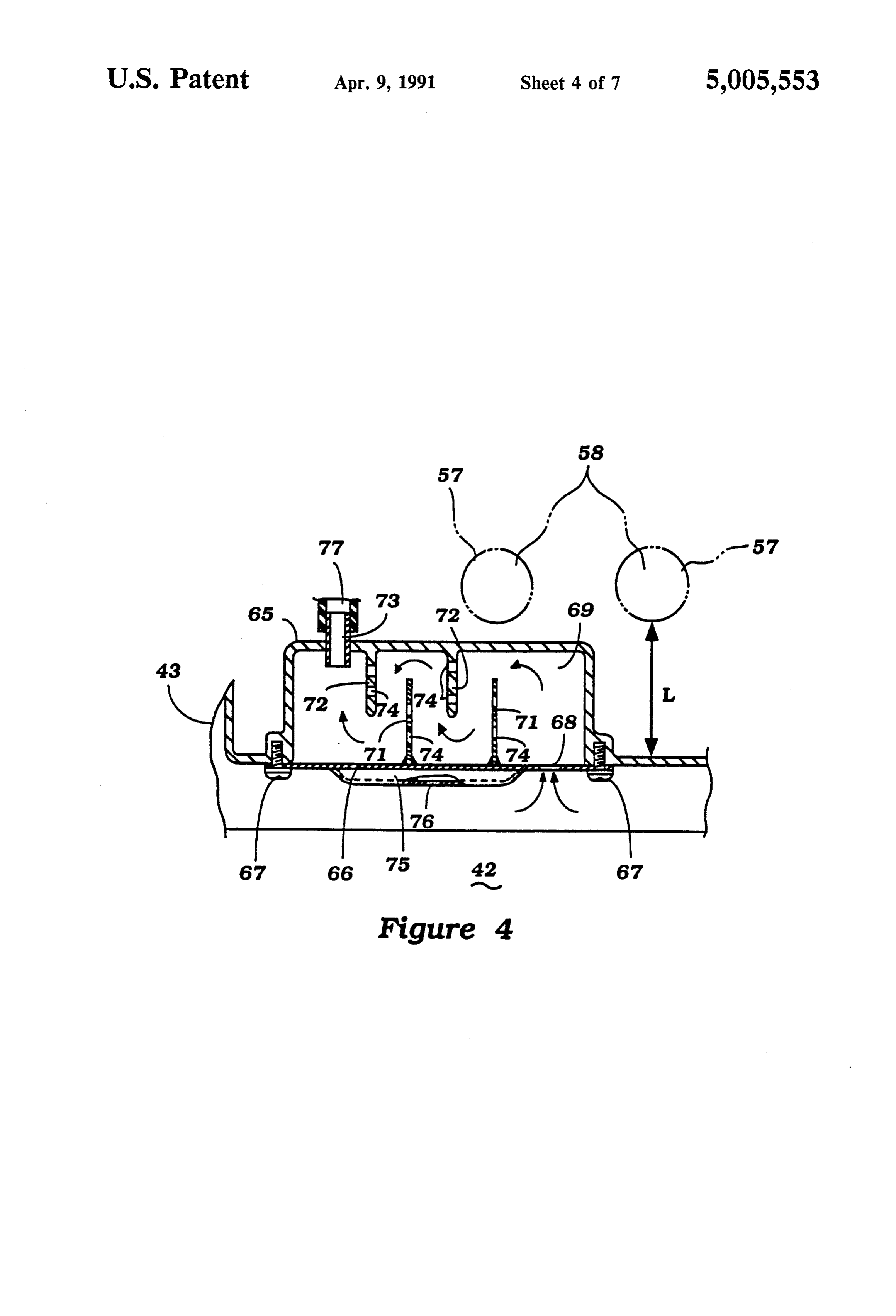
the other side of the engine. However, where the engine has overhead valves and overhead camshafts, the posi theFIG. 4 is an enlarged cross sectional view taken along
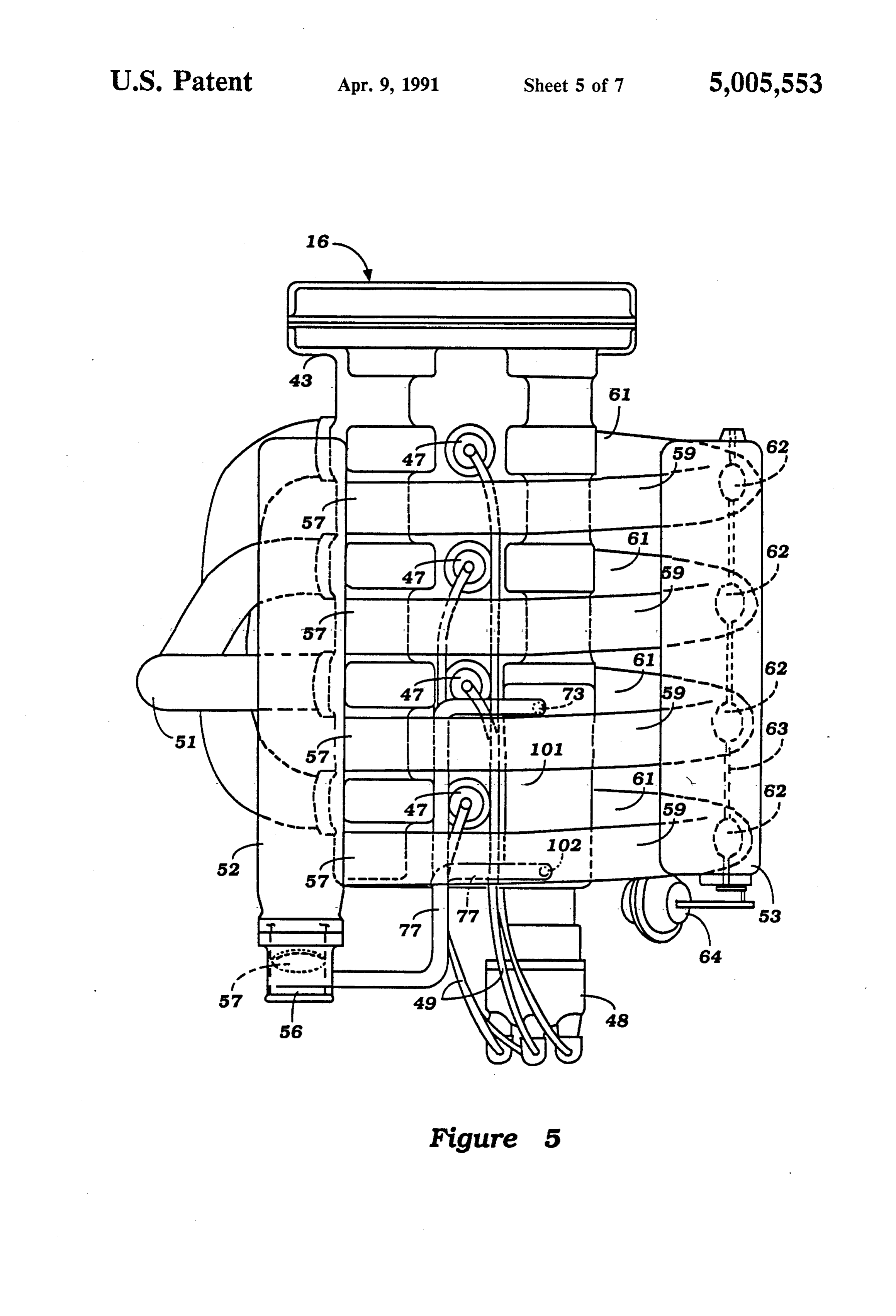
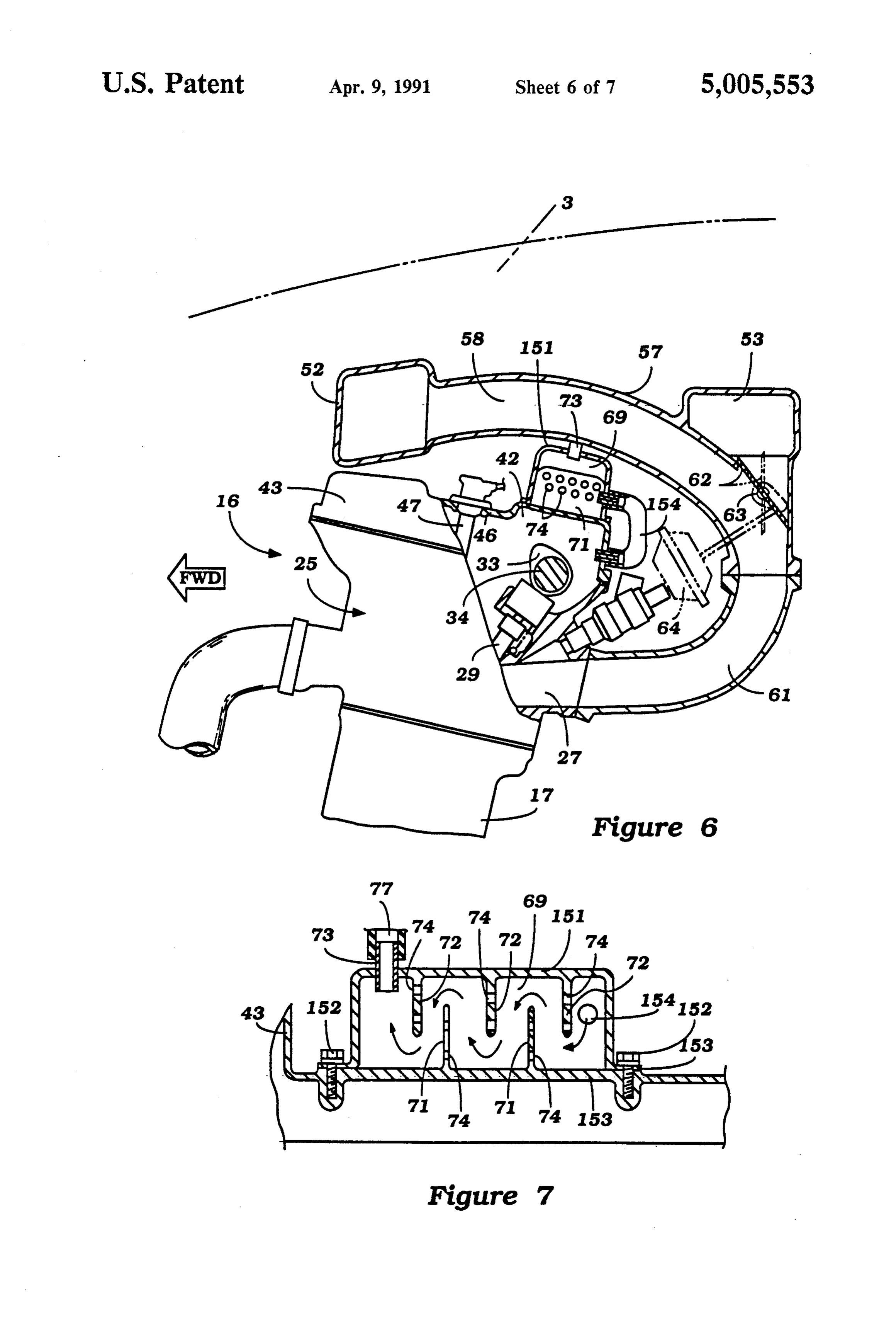
tioning of the intake manifold over the cylinder head FIG. 5 is a top plan view, in part similar to FIG. 3, can give rise to spatial problems. In addition, such an 30 showing another embodiment of the invention. orientation can adversely effect the hood line of the FIG. 6 is a side elevational view, with a portion vehicle. Since it is important to provide a low hood line shown in section, of yet another embodiment of the for both aerodynamic and styling purposes, it must be invention.
insured that the height of the engine is not too great.
Furthermore, all engines employ a crankcase venti 35 FIG. 7 is a cross sectional view taken through the oil lating system for causing ventilating air to flow through separator of this embodiment.
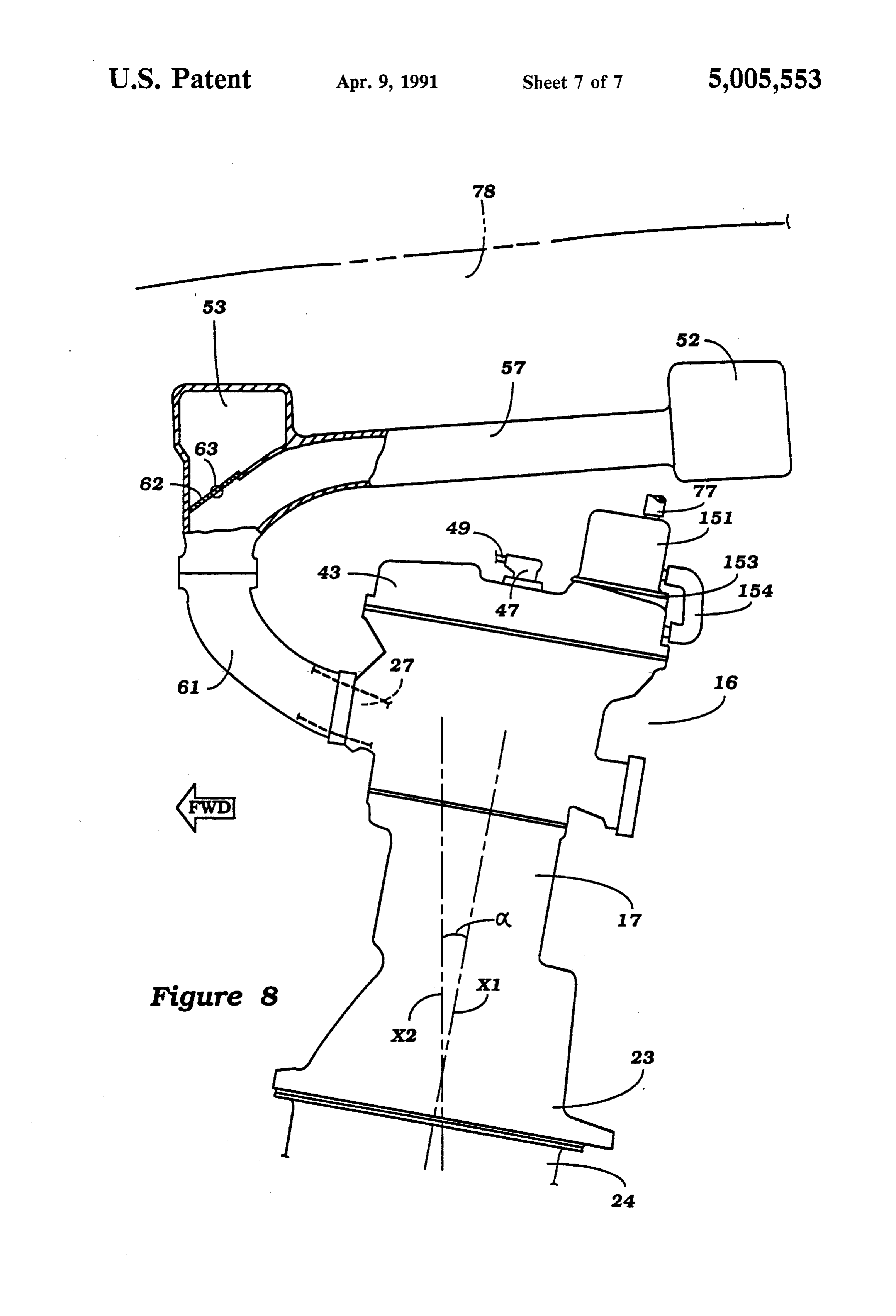
the internal portions of the engine and particularly over FIG. 8 is a side elevational view, with a portion bro the oil in the crankcase and through the cam chamber of ken away, of another embodiment of the invention. the cylinder head. It is normally the practice to employ DETALED DESCRIPTION OF THE some form of oil separator to separate lubricant from 40 PREFERRED EMBODIMENTS OF THE the circulated air so that the lubricant will not be dis INVENTION charged to the atmosphere. In addition, if the lubricant is not removed from the circulating air, the quantity of Referring first in detail to FIG. 1, a motor vehicle oil in the lubricating system can become depleted. powered by an internal combustion engine having an With many types of engines, particularly those of the 45 induction system constructed in accordance with an in line type, it has been the practice to position the oil embodiment of the invention is identified generally by separator in the cam cover of the engine. Of course, the the reference numeral 11. Only the forward portion of oil separator must have a certain volume to operate the vehicle 11 is shown and specifically the engine com effectively. If the intake system passes over the cylinder partment 12 that is defined by a pair offender aprons 13 head and oil separator, then the height of the engine can 50 and a front grille opening 14 behind which a cooling be significantly increased. radiator 15 is positioned. The hood is removed in FIG. It is, therefore, a principal object of this invention to 1 to more clearly show the construction. provide an improved oil separator and manifold ar An internal combustion engine, constructed in accor rangement for an internal combustion engine that per dance with an embodiment of the invention is identified mits a low overall height without sacrificing any of the 55 generally by the reference numeral 16 and, in the illus functional aspects of the engine. trated embodiment, comprises a four cylinder in line It is a further object of this invention to provide an engine that is positioned transversely across the engine improved engine construction wherein an oil separator compartment 12. The engine 16 drives the front wheels can be positioned in the head assembly of the engine, (not shown) of the vehicle 11 through a suitable trans the intake manifold can pass at least in part over the oil mission and differential mechanism as is well known in separator and the engine nevertheless has a low overall this art.
height. Referring now additionally to FIGS. 2 and 3, the SUMMARY OF THE INVENTION engine 16, as has been previously noted, is of the four cylinder in line type. To this end, a cylinder block 17 is
This invention is adapted to be embodied in an inter 65 provided with four aligned cylinder bores 18 in which nal combustion engine having a cylinder block with at pistons 19 reciprocate. The pistons 19 are connected by least one cylinder bore therein. A cylinder head assem means of connecting rods 21 to individual throws of a bly is affixed to the cylinder block and closes the cylin crankshaft 22 for driving the crankshaft as is well
Page 10
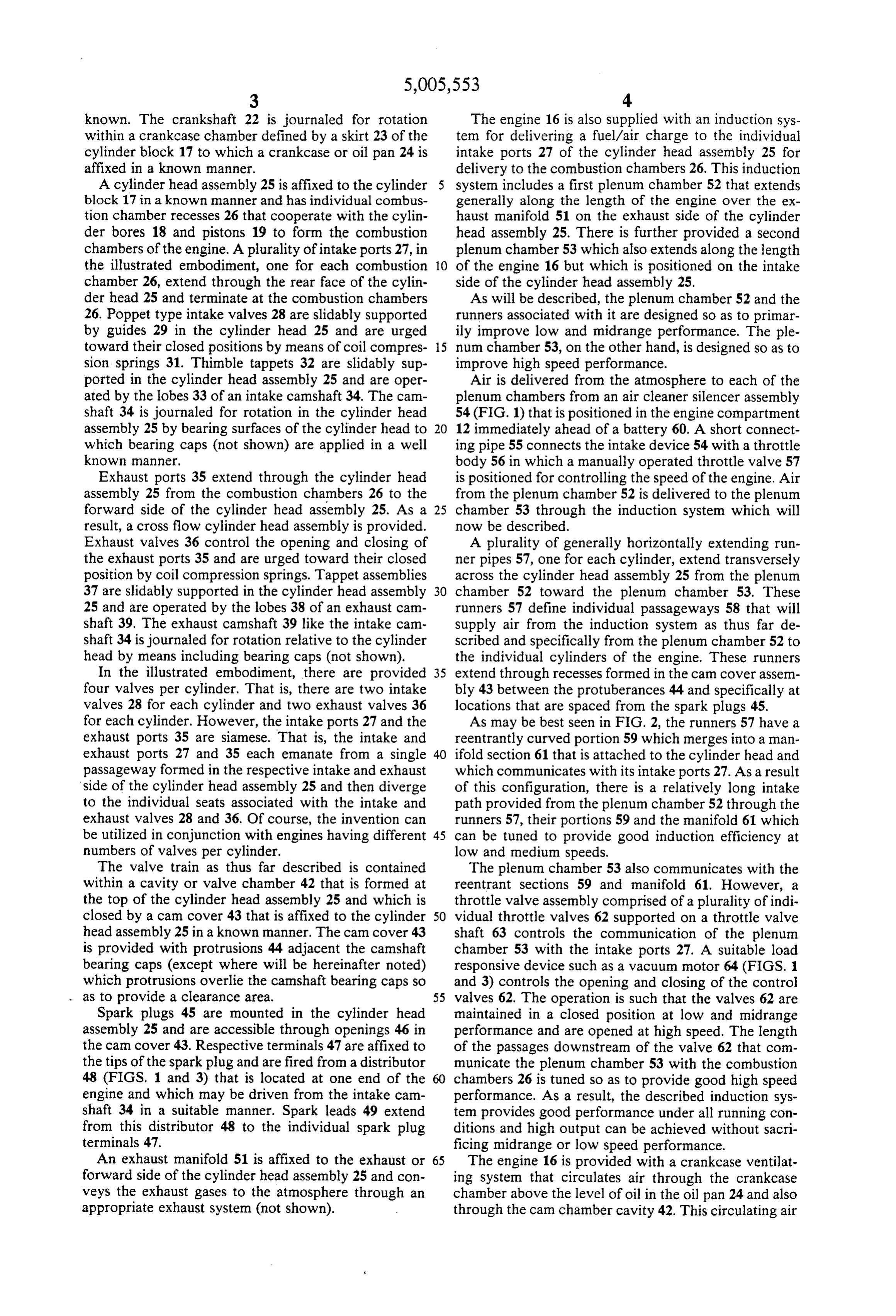
known. The crankshaft 22 is journaled for rotation The engine 16 is also supplied with an induction sys within a crankcase chamber defined by a skirt 23 of the tem for delivering a fuel/air charge to the individual cylinder block 17 to which a crankcase or oil pan 24 is intake ports 27 of the cylinder head assembly 25 for affixed in a known manner. delivery to the combustion chambers 26. This induction A cylinder head assembly 25 is affixed to the cylinder system includes a first plenum chamber 52 that extends block 17 in a known manner and has individual combus generally along the length of the engine over the ex tion chamber recesses 26 that cooperate with the cylin haust manifold 51 on the exhaust side of the cylinder der bores 18 and pistons 19 to form the combustion head assembly 25. There is further provided a second chambers of the engine. A plurality of intake ports 27, in plenum chamber 53 which also extends along the length the illustrated embodiment, one for each combustion 10 of the engine 16 but which is positioned on the intake chamber 26, extend through the rear face of the cylin side of the cylinder head assembly 25. der head 25 and terminate at the combustion chambers As will be described, the plenum chamber 52 and the 26. Poppet type intake valves 28 are slidably supported runners associated with it are designed so as to primar by guides 29 in the cylinder head 25 and are urged ily improve low and midrange performance. The ple toward their closed positions by means of coil compres 15 num chamber 53, on the other hand, is designed so as to sion springs 31. Thimble tappets 32 are slidably sup improve high speed performance.
ported in the cylinder head assembly 25 and are oper Air is delivered from the atmosphere to each of the ated by the lobes 33 of an intake camshaft 34. The cam plenum chambers from an air cleaner silencer assembly shaft 34 is journaled for rotation in the cylinder head 54 (FIG. 1) that is positioned in the engine compartment assembly 25 by bearing surfaces of the cylinder head to 20 12 immediately ahead of a battery 60. A short connect which bearing caps (not shown) are applied in a well ing pipe 55 connects the intake device 54 with a throttle known manner. body 56 in which a manually operated throttle valve 57 Exhaust ports 35 extend through the cylinder head is positioned for controlling the speed of the engine. Air assembly 25 from the combustion chambers 26 to the from the plenum chamber 52 is delivered to the plenum forward side of the cylinder head assembly 25. As a 25 chamber 53 through the induction system which will result, a cross flow cylinder head assembly is provided. now be described.
Exhaust valves 36 control the opening and closing of A plurality of generally horizontally extending run the exhaust ports 35 and are urged toward their closed ner pipes 57, one for each cylinder, extend transversely position by coil compression springs. Tappet assemblies across the cylinder head assembly 25 from the plenum 37 are slidably supported in the cylinder head assembly 30 chamber 52 toward the plenum chamber 53. These 25 and are operated by the lobes 38 of an exhaust cam runners 57 define individual passageways 58 that will shaft 39. The exhaust camshaft 39 like the intake cam supply air from the induction system as thus far de shaft 34 is journaled for rotation relative to the cylinder scribed and specifically from the plenum chamber 52 to head by means including bearing caps (not shown). the individual cylinders of the engine. These runners In the illustrated embodiment, there are provided 35 extend through recesses formed in the cam cover assem four valves per cylinder. That is, there are two intake bly 43 between the protuberances 44 and specifically at valves 28 for each cylinder and two exhaust valves 36 locations that are spaced from the spark plugs 45. for each cylinder. However, the intake ports 27 and the As may be best seen in FIG. 2, the runners 57 have a exhaust ports 35 are siamese. That is, the intake and reentrantly curved portion 59 which merges into a man exhaust ports 27 and 35 each emanate from a single ifold section 61 that is attached to the cylinder head and passageway formed in the respective intake and exhaust which communicates with its intake ports 27. As a result side of the cylinder head assembly 25 and then diverge of this configuration, there is a relatively long intake to the individual seats associated with the intake and path provided from the plenum chamber 52 through the exhaust valves 28 and 36. Of course, the invention can runners 57, their portions 59 and the manifold 61 which be utilized in conjunction with engines having different 45 can be tuned to provide good induction efficiency at numbers of valves per cylinder. low and medium speeds.
The valve train as thus far described is contained The plenum chamber 53 also communicates with the within a cavity or valve chamber 42 that is formed at reentrant sections 59 and manifold 61. However, a the top of the cylinder head assembly 25 and which is throttle valve assembly comprised of a plurality of indi closed by a cam cover 43 that is affixed to the cylinder 50 vidual throttle valves 62 supported on a throttle valve head assembly 25 in a known manner. The can cover 43 shaft 63 controls the communication of the plenum is provided with protrusions 44 adjacent the camshaft chamber 53 with the intake ports 27. A suitable load bearing caps (except where will be hereinafter noted) responsive device such as a vacuum motor 64 (FIGS. 1 which protrusions overlie the camshaft bearing caps so and 3) controls the opening and closing of the control . . as to provide a clearance area. 55 valves 62. The operation is such that the valves 62 are Spark plugs 45 are mounted in the cylinder head maintained in a closed position at low and midrange assembly 25 and are accessible through openings 46 in performance and are opened at high speed. The length the cam cover 43. Respective terminals 47 are affixed to of the passages downstream of the valve 62 that com the tips of the spark plug and are fired from a distributor municate the plenum chamber 53 with the combustion 48 (FIGS. 1 and 3) that is located at one end of the chambers 26 is tuned so as to provide good high speed engine and which may be driven from the intake cam performance. As a result, the described induction sys shaft 34 in a suitable manner. Spark leads 49 extend tem provides good performance under all running con from this distributor 48 to the individual spark plug ditions and high output can be achieved without sacri terminals 47. ficing midrange or low speed performance. An exhaust manifold 51 is affixed to the exhaust or 65 The engine 16 is provided with a crankcase ventilat forward side of the cylinder head assembly 25 and con ing system that circulates air through the crankcase veys the exhaust gases to the atmosphere through an chamber above the level of oil in the oil pan 24 and also appropriate exhaust system (not shown). through the cam chamber cavity 42. This circulating air
Page 11
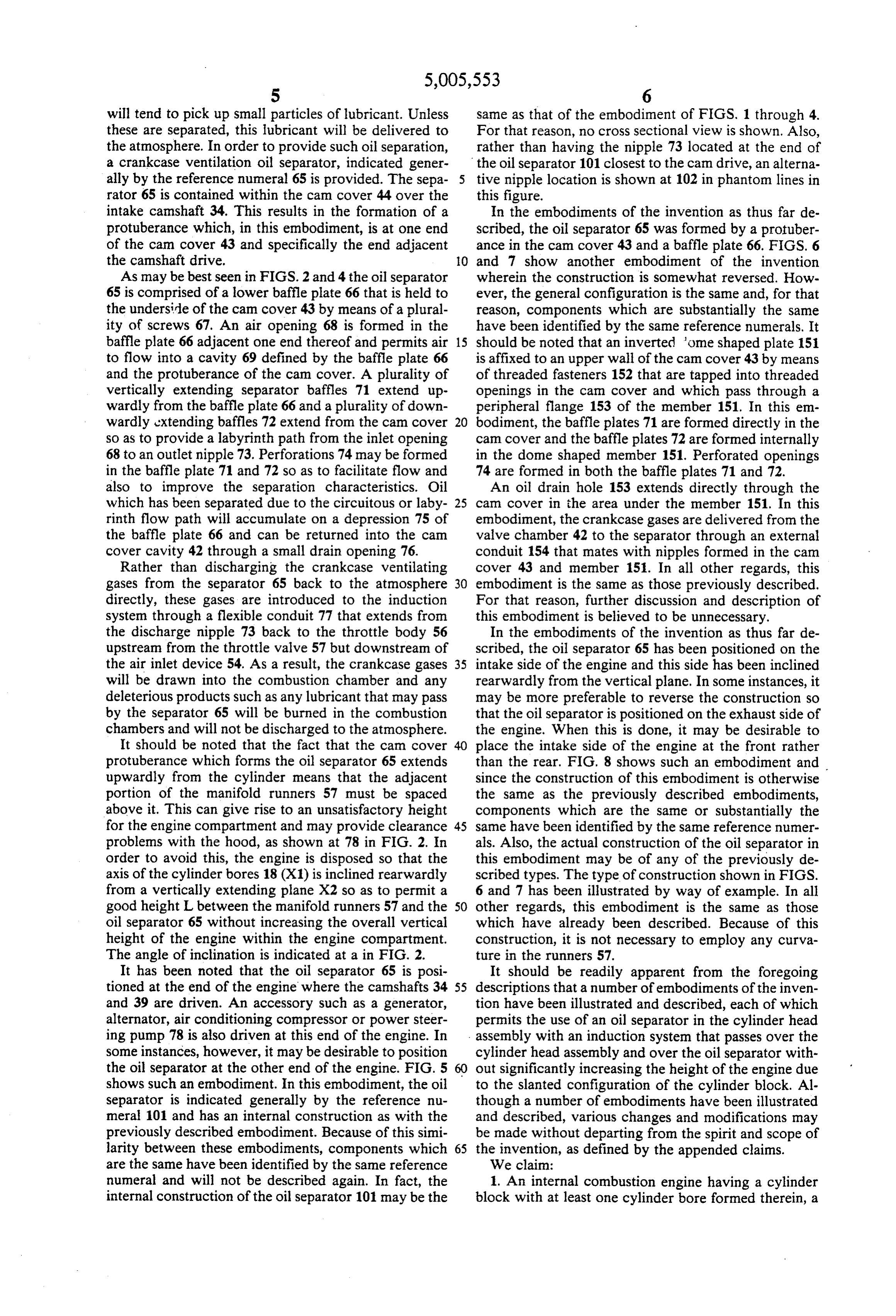
will tend to pick up small particles of lubricant. Unless same as that of the embodiment of FIGS. 1 through 4. these are separated, this lubricant will be delivered to For that reason, no cross sectional view is shown. Also, the atmosphere. In order to provide such oil separation, rather than having the nipple 73 located at the end of a crankcase ventilation oil separator, indicated gener the oil separator 101 closest to the cam drive, an alterna ally by the reference numeral 65 is provided. The sepa tive nipple location is shown at 102 in phantom lines in rator 65 is contained within the cam cover 44 over the this figure.
intake camshaft 34. This results in the formation of a In the embodiments of the invention as thus far de protuberance which, in this embodiment, is at one end scribed, the oil separator 65 was formed by a protuber of the cam cover 43 and specifically the end adjacent ance in the cam cover 43 and a baffle plate 66. FIGS. 6 the camshaft drive. 10 and 7 show another embodiment of the invention As may be best seen in FIGS. 2 and 4 the oil separator wherein the construction is somewhat reversed. How 65 is comprised of a lower baffle plate 66 that is held to ever, the general configuration is the same and, for that the underside of the cam cover 43 by means of a plural reason, components which are substantially the same ity of screws 67. An air opening 68 is formed in the have been identified by the same reference numerals. It baffle plate 66 adjacent one end thereof and permits air 15 should be noted that an inverted 'ome shaped plate 151 to flow into a cavity 69 defined by the baffle plate 66 is affixed to an upper wall of the cam cover 43 by means and the protuberance of the cam cover. A plurality of of threaded fasteners 152 that are tapped into threaded vertically extending separator baffles 71 extend up openings in the can cover and which pass through a wardly from the baffle plate 66 and a plurality of down peripheral flange 153 of the member 151. In this em wardly extending baffles 72 extend from the cam cover 20 bodiment, the baffle plates 71 are formed directly in the so as to provide a labyrinth path from the inlet opening cam cover and the baffle plates 72 are formed internally 68 to an outlet nipple 73. Perforations 74 may be formed in the dome shaped member 151. Perforated openings in the baffle plate 71 and 72 so as to facilitate flow and 74 are formed in both the baffle plates 71 and 72. also to improve the separation characteristics. Oil An oil drain hole 153 extends directly through the which has been separated due to the circuitous or laby 25 cam cover in the area under the member 151. In this rinth flow path will accumulate on a depression 75 of embodiment, the crankcase gases are delivered from the the baffle plate 66 and can be returned into the cam valve chamber 42 to the separator through an external cover cavity 42 through a small drain opening 76. conduit 154 that mates with nipples formed in the cam Rather than discharging the crankcase ventilating cover 43 and member 151. In all other regards, this gases from the separator 65 back to the atmosphere 30 embodiment is the same as those previously described. directly, these gases are introduced to the induction For that reason, further discussion and description of system through a flexible conduit 77 that extends from this embodiment is believed to be unnecessary. the discharge nipple 73 back to the throttle body 56 In the embodiments of the invention as thus far de upstream from the throttle valve 57 but downstream of scribed, the oil separator 65 has been positioned on the the air inlet device 54. As a result, the crankcase gases 35 intake side of the engine and this side has been inclined will be drawn into the combustion chamber and any rearwardly from the vertical plane. In some instances, it deleterious products such as any lubricant that may pass may be more preferable to reverse the construction so by the separator 65 will be burned in the combustion that the oil separator is positioned on the exhaust side of chambers and will not be discharged to the atmosphere. the engine. When this is done, it may be desirable to It should be noted that the fact that the cam cover place the intake side of the engine at the front rather protuberance which forms the oil separator 65 extends than the rear. FIG. 8 shows such an embodiment and upwardly from the cylinder means that the adjacent since the construction of this embodiment is otherwise portion of the manifold runners 57 must be spaced the same as the previously described embodiments, above it. This can give rise to an unsatisfactory height components which are the same or substantially the for the engine compartment and may provide clearance 45 same have been identified by the same reference numer problems with the hood, as shown at 78 in FIG. 2. In als. Also, the actual construction of the oil separator in order to avoid this, the engine is disposed so that the this embodiment may be of any of the previously de axis of the cylinder bores 18 (X1) is inclined rearwardly scribed types. The type of construction shown in FIGS. from a vertically extending plane X2 so as to permit a 6 and 7 has been illustrated by way of example. In all good height L between the manifold runners 57 and the 50 other regards, this embodiment is the same as those oil separator 65 without increasing the overall vertical which have already been described. Because of this height of the engine within the engine compartment. construction, it is not necessary to employ any curva The angle of inclination is indicated at a in FIG. 2. ture in the runners 57.
It has been noted that the oil separator 65 is posi It should be readily apparent from the foregoing tioned at the end of the engine where the camshafts 34 55 descriptions that a number of embodiments of the inven and 39 are driven. An accessory such as a generator, tion have been illustrated and described, each of which alternator, air conditioning compressor or power steer permits the use of an oil separator in the cylinder head ing pump 78 is also driven at this end of the engine. In assembly with an induction system that passes over the some instances, however, it may be desirable to position cylinder head assembly and over the oil separator with the oil separator at the other end of the engine. FIG. 5 out significantly increasing the height of the engine due shows such an embodiment. In this embodiment, the oil to the slanted configuration of the cylinder block. Al separator is indicated generally by the reference nu though a number of embodiments have been illustrated meral 101 and has an internal construction as with the and described, various changes and modifications may previously described embodiment. Because of this simi be made without departing from the spirit and scope of larity between these embodiments, components which 65 the invention, as defined by the appended claims. are the same have been identified by the same reference We claim:
numeral and will not be described again. In fact, the 1. An internal combustion engine having a cylinder internal construction of the oil separator 101 may be the block with at least one cylinder bore formed therein, a
Page 12
cylinder head assembly affixed to said cylinder block 5. An internal combustion engine as set forth in claim and closing said cylinder bore, a crankcase ventilation 4 wherein the engine is inclined from the vertical oil separator affixed to said cylinder head assembly and toward the crankcase ventilation oil separator side of protruding at least in part upwardly therefrom, an in the cylinder head.
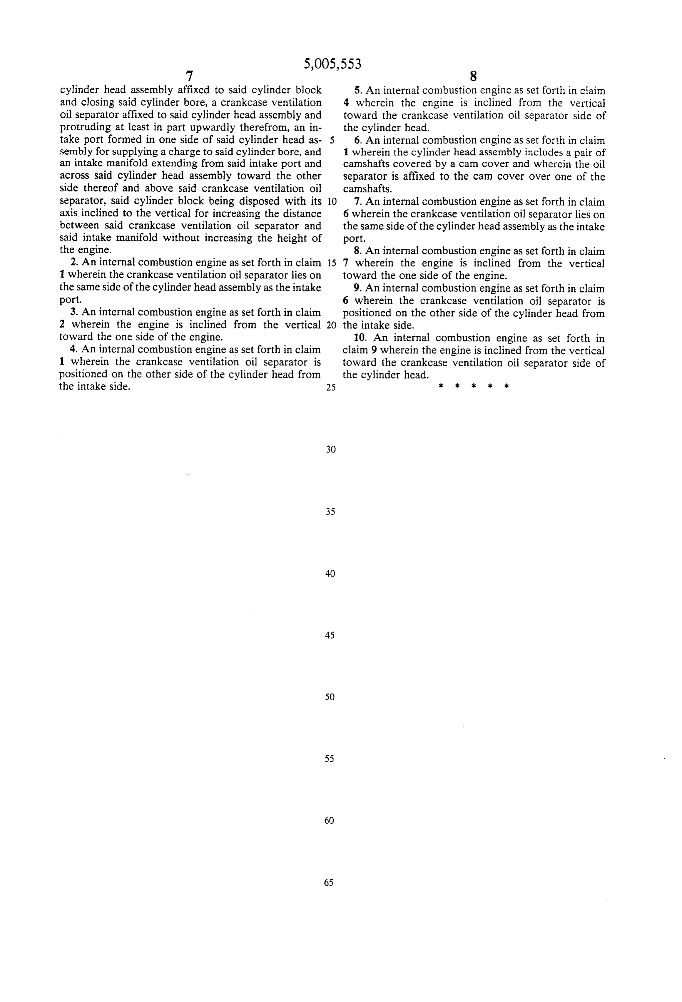
take port formed in one side of said cylinder head as 6. An internal combustion engine as set forth in claim sembly for supplying a charge to said cylinder bore, and 1 wherein the cylinder head assembly includes a pair of an intake manifold extending from said intake port and camshafts covered by a cam cover and wherein the oil across said cylinder head assembly toward the other separator is affixed to the cam cover over one of the side thereof and above said crankcase ventilation oil camshafts.
separator, said cylinder block being disposed with its 10 7. An internal combustion engine as set forth in claim axis inclined to the vertical for increasing the distance 6 wherein the crankcase ventilation oil separator lies on between said crankcase ventilation oil separator and the same side of the cylinder head assembly as the intake said intake manifold without increasing the height of port.
the engine. 8. An internal combustion engine as set forth in claim 2. An internal combustion engine as set forth in claim 15 7 wherein the engine is inclined from the vertical 1 wherein the crankcase ventilation oil separator lies on toward the one side of the engine. the same side of the cylinder head assembly as the intake 9. An internal combustion engine as set forth in claim port. 6 wherein the crankcase ventilation oil separator is 3. An internal combustion engine as set forth in claim positioned on the other side of the cylinder head from 2 wherein the engine is inclined from the vertical 20 the intake side.
toward the one side of the engine. 10. An internal combustion engine as set forth in 4. An internal combustion engine as set forth in claim claim 9 wherein the engine is inclined from the vertical 1 wherein the crankcase ventilation oil separator is toward the crankcase ventilation oil separator side of positioned on the other side of the cylinder head from the cylinder head.
the intake side. 25 ck k sk 2k k
Provenance
- Collection
- Cited prior art
- Original PDF
- patentimages.storage.googleapis.com →
- Filed
- 1990-02-27
- Pages
- 12
- Method
- pdftotext (the PDF's own text layer) + pdftoppm 300dpi page scans
- Source
- Google Patents bibliographic record
- Granted
- 1991-04-09
- Inventors
- Takehiro Washizu; Tsutomu Nagamatsu; Yamaha Motor Co Ltd
- Transcribed from
- patentimages.storage.googleapis.com →