patent · US6138644
Apparatus and method for processing fuel vapor in internal combustion engine
31 October 2000
Page 1 — bibliographic record
United States Patent (19) 11 Patent Number: 6,138,644
Saruwatari et al. (45) Date of Patent: Oct. 31,9 2000
54). APPARATUS AND METHOD FOR 5,190,015 3/1993 Nakata et al. .......................... 123/520 PROCESSING FUEL WAPOR IN INTERNAL 5,269,278 12/1993 Heinemann et al. ................... 123/520 COMBUSTION ENGINE 5,349.935 9/1994 Mezger et al........................... 123/520 5,881,700 3/1999 Gras et al. .............................. 123/520 (75) Inventors: Masayuki Saruwatari; Junichi 5,918,580 7/1999 Hennrich et al. ---- ------------- --- --- 123/520
Furuya, both of Atsugi, Japan FOREIGN PATENT DOCUMENTS 73 Assignee: Unisia Jecs Corporation, Atsugi, Japan 58-110852 7/1983 Japan.
21 Appl. No.: 09/199,280 5-312113 11/1993 Japan.
Primary Examiner Thomas N. Moulis 22 Filed: Nov. 25, 1998 Attorney, Agent, or Firm-Foley & Lardner 30 Foreign Application Priority Data 57 ABSTRACT Sep. 12, 1997 JP Japan .................................... 9-338775 A purge passage is communicated to the upstream Side of a (51) Int. Cl. ............................................... F02M 37/04 compressor of a turboSupercharger, and on the other hand, a 52 U.S. Cl. ............................................. 123/520; 123/519 purge control valve and an electrically powered pump are 58 Field of Search ..................................... 123/516, 518, mounted in the middle of Saidpurge passage. Then, either a 123/519, 520, 521 constant drive current is provided to Said electrically pow ered pump, and the opening of the purge control valve is 56) References Cited controlled in correspondence to the requested purged air flow rate, or the purge control valve is controlled to be fully
4,541,396 9/1985 Sato et al. ............................... 123,520 correspondence to the requested purged air flow rate. 5,005,550 4/1991 Bugin, Jr. et al. ...................... 123/520 5,183,023 2/1993 Hanson ................................... 123/520 5 Claims, 3 Drawing Sheets
2O Qs
YN (e) 16 6
Page 2
Drawing sheet — no readable text.
Page 3
START
S1 READ-IN ROTATION
SPEED NEETC.
S2 CALCULATE REGUESTED
PURGED AIR FOW RATE
S3 REGUEST FOR
PURGING EXISTS
VALVE FULLY OPENED VALVE FULLY CLOSED
S7 -N. CUT DOWN PUMP
DRIVE CURRENT
DRIVE
CURRENT
REGUESTED PURGED
AR FLOW RATE
OUTPUT DRIVE CURRENT
Page 4
START
S1 READ-IN ROTATION
SPEED NEETC.
S2 CALCULATE REGUESTED
PURGED AR FLOW RATE
S3 REGUEST FOR
PURGING EXISTS
S6A OUTPUT CONSTANT PURGE CONTROL
DRIVE CURRENT TO PUMP VALVE FULLY CLOSED
CUT DOWN PUMP
DRIVE CURRENT
TARGET
OPENING
REGUESTED PURGED
AR FLOW RATE
CONTROL OPENING OF
PURGE CONTROL VALVE
Page 5
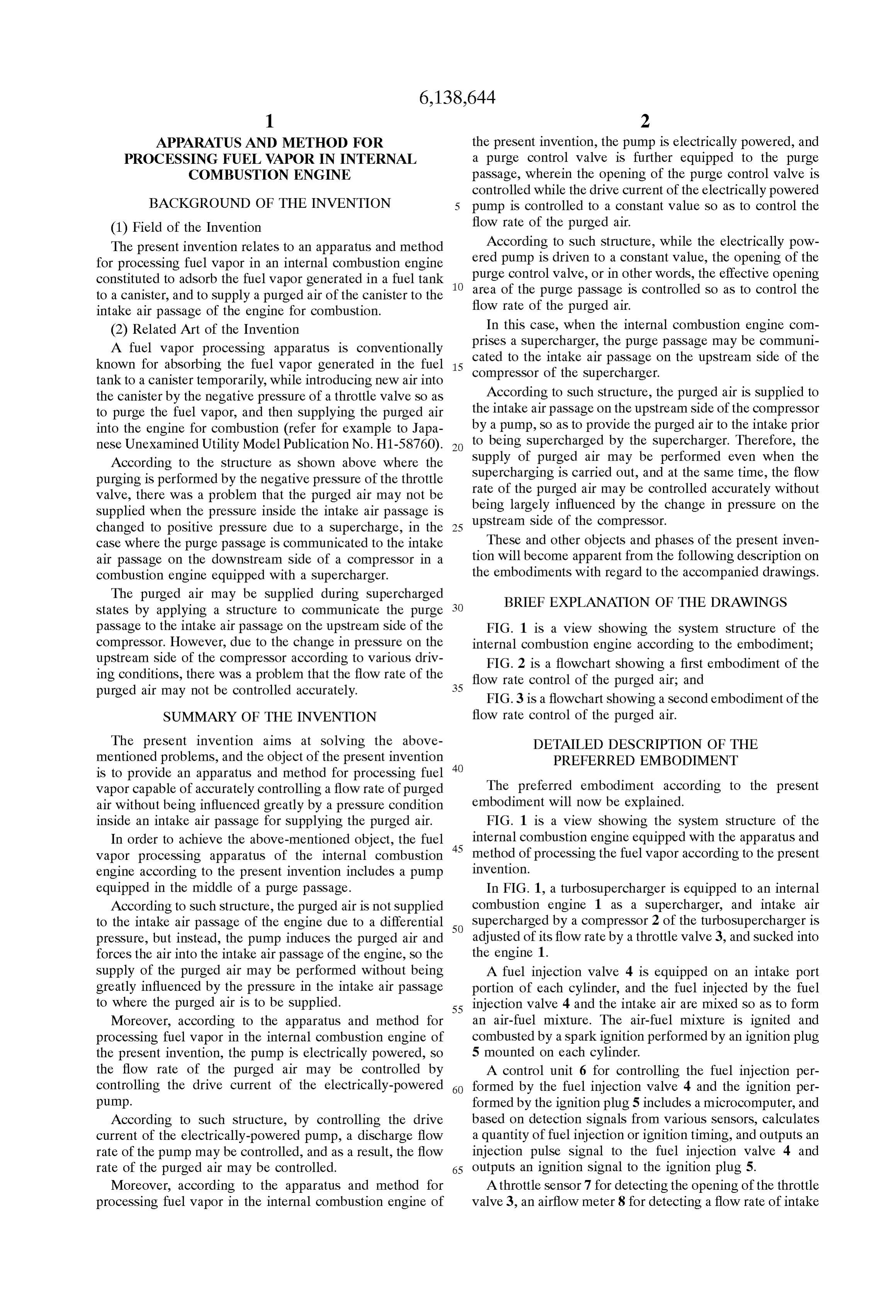
APPARATUS AND METHOD FOR the present invention, the pump is electrically powered, and PROCESSING FUEL WAPOR IN INTERNAL a purge control valve is further equipped to the purge COMBUSTION ENGINE passage, wherein the opening of the purge control valve is controlled while the drive current of the electrically powered
BACKGROUND OF THE INVENTION pump is controlled to a constant value So as to control the (1) Field of the Invention flow rate of the purged air.
The present invention relates to an apparatus and method According to Such structure, while the electrically pow for processing fuel vapor in an internal combustion engine ered pump is driven to a constant value, the opening of the constituted to adsorb the fuel vapor generated in a fuel tank purge control valve, or in other words, the effective opening to a canister, and to Supply a purged air of the canister to the area of the purge passage is controlled So as to control the intake air passage of the engine for combustion. flow rate of the purged air.
(2) Related Art of the Invention In this case, when the internal combustion engine com A fuel vapor processing apparatus is conventionally prises a Supercharger, the purge passage may be communi known for absorbing the fuel vapor generated in the fuel 15 cated to the intake air passage on the upstream Side of the compressor of the Supercharger.
tank to a canister temporarily, while introducing new air into the canister by the negative pressure of a throttle Valve So as According to Such structure, the purged air is Supplied to to purge the fuel vapor, and then Supplying the purged air the intake air passage on the upstream Side of the compressor into the engine for combustion (refer for example to Japa by a pump, So as to provide the purged air to the intake prior nese Unexamined Utility Model Publication No. H1-58760). to being Supercharged by the Supercharger. Therefore, the According to the Structure as shown above where the Supply of purged air may be performed even when the Supercharging is carried out, and at the same time, the flow purging is performed by the negative pressure of the throttle
Valve, there was a problem that the purged air may not be being rate of the purged air may be controlled accurately without Supplied when the pressure inside the intake air passage is upstream largely influenced by the change in pressure on the changed to positive pressure due to a Supercharge, in the 25 Side of the compressor. case where the purge passage is communicated to the intake These and other objects and phases of the present inven air passage on the downstream Side of a compressor in a tion will become apparent from the following description on combustion engine equipped with a Supercharger. the embodiments with regard to the accompanied drawings. The purged air may be Supplied during Supercharged BRIEF EXPLANATION OF THE DRAWINGS States by applying a structure to communicate the purge passage to the intake air passage on the upstream Side of the FIG. 1 is a view showing the system structure of the compressor. However, due to the change in pressure on the internal combustion engine according to the embodiment; upstream side of the compressor according to various driv FIG. 2 is a flowchart showing a first embodiment of the ing conditions, there was a problem that the flow rate of the flow rate control of the purged air; and purged air may not be controlled accurately. 35
FIG. 3 is a flowchart showing a second embodiment of the
SUMMARY OF THE INVENTION flow rate control of the purged air.
The present invention aims at Solving the above DETAILED DESCRIPTION OF THE mentioned problems, and the object of the present invention 40 PREFERRED EMBODIMENT is to provide an apparatus and method for processing fuel
Vapor capable of accurately controlling a flow rate of purged The preferred embodiment according to the present air without being influenced greatly by a pressure condition embodiment will now be explained.
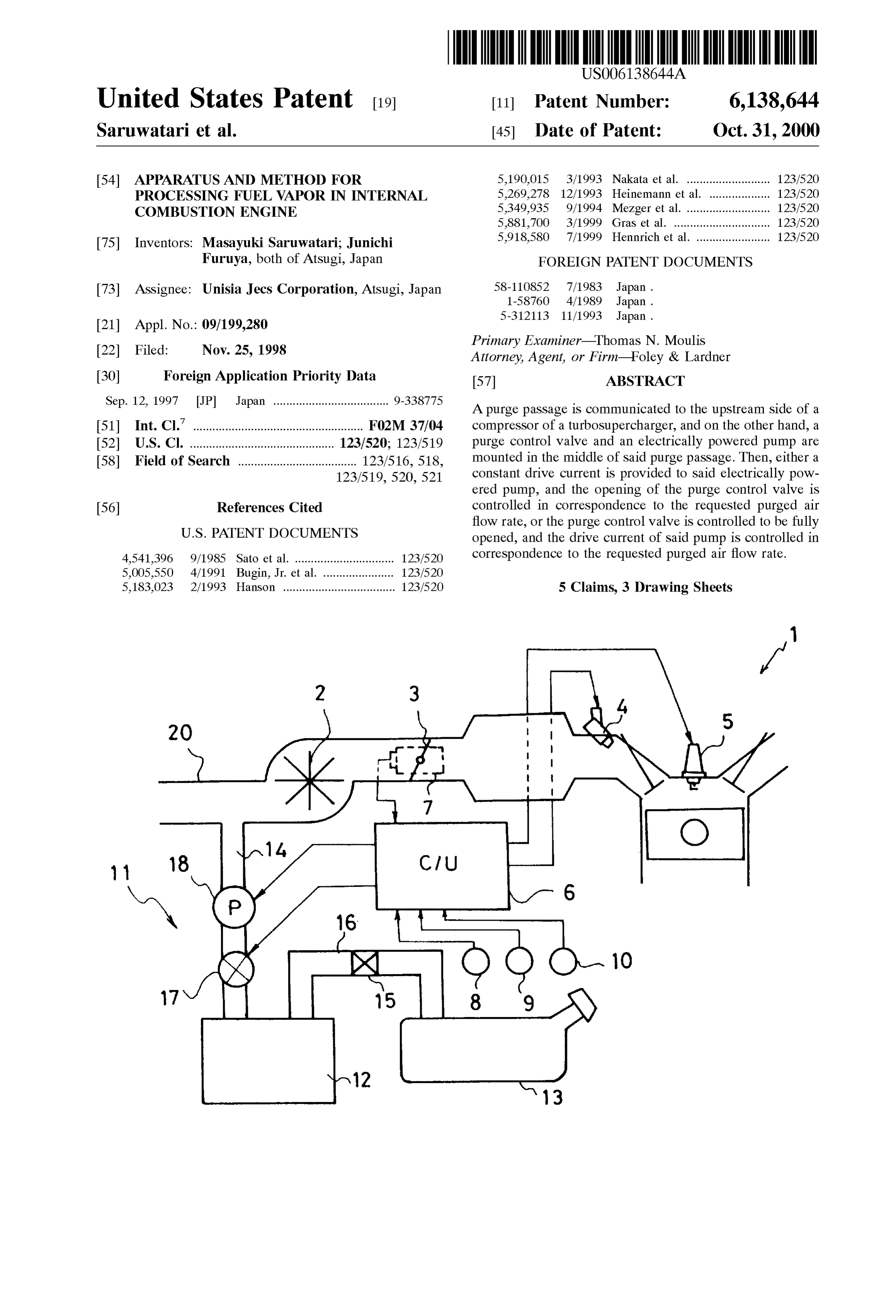
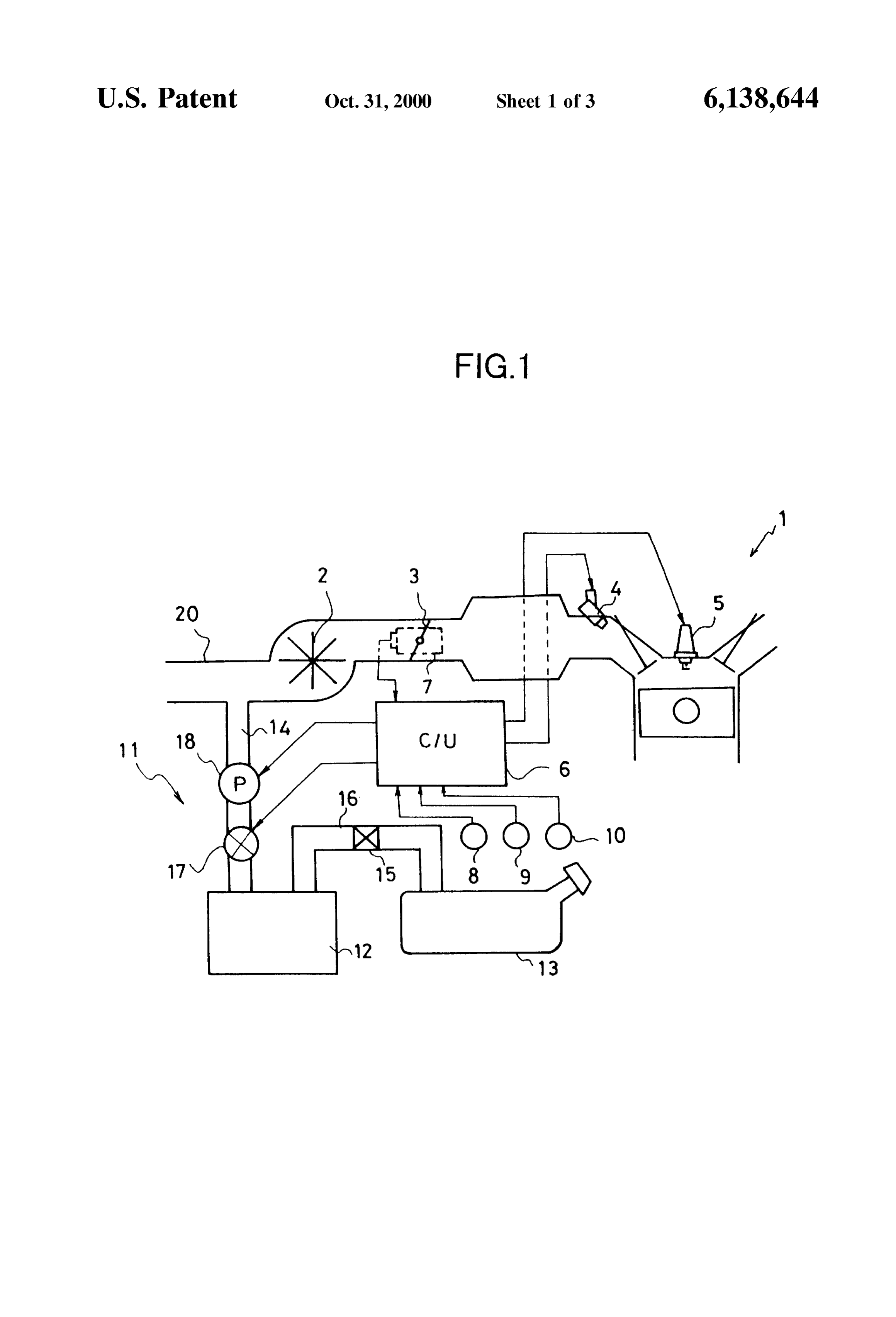
inside an intake air passage for Supplying the purged air. FIG. 1 is a view showing the system structure of the In order to achieve the above-mentioned object, the fuel 45 internal combustion engine equipped with the apparatus and Vapor processing apparatus of the internal combustion method of processing the fuel vapor according to the present engine according to the present invention includes a pump invention.
equipped in the middle of a purge passage. In FIG. 1, a turboSupercharger is equipped to an internal According to Such structure, the purged air is not Supplied combustion engine 1 as a Supercharger, and intake air to the intake air passage of the engine due to a differential 50 Supercharged by a compressor 2 of the turboSupercharger is preSSure, but instead, the pump induces the purged air and adjusted of its flow rate by a throttle valve 3, and Sucked into forces the air into the intake air passage of the engine, So the the engine 1.
Supply of the purged air may be performed without being A fuel injection valve 4 is equipped on an intake port greatly influenced by the preSSure in the intake air passage portion of each cylinder, and the fuel injected by the fuel to where the purged air is to be Supplied. 55 injection valve 4 and the intake air are mixed So as to form Moreover, according to the apparatus and method for an air-fuel mixture. The air-fuel mixture is ignited and processing fuel vapor in the internal combustion engine of combusted by a Spark ignition performed by an ignition plug the present invention, the pump is electrically powered, So 5 mounted on each cylinder.
the flow rate of the purged air may be controlled by A control unit 6 for controlling the fuel injection per controlling the drive current of the electrically-powered 60 formed by the fuel injection Valve 4 and the ignition per pump. formed by the ignition plug 5 includes a microcomputer, and According to Such structure, by controlling the drive based on detection signals from various Sensors, calculates current of the electrically-powered pump, a discharge flow a quantity of fuel injection or ignition timing, and outputs an rate of the pump may be controlled, and as a result, the flow injection pulse Signal to the fuel injection Valve 4 and rate of the purged air may be controlled. 65 outputs an ignition signal to the ignition plug 5. Moreover, according to the apparatus and method for A throttle sensor 7 for detecting the opening of the throttle processing fuel vapor in the internal combustion engine of valve 3, an airflow meter 8 for detecting a flow rate of intake
Page 6
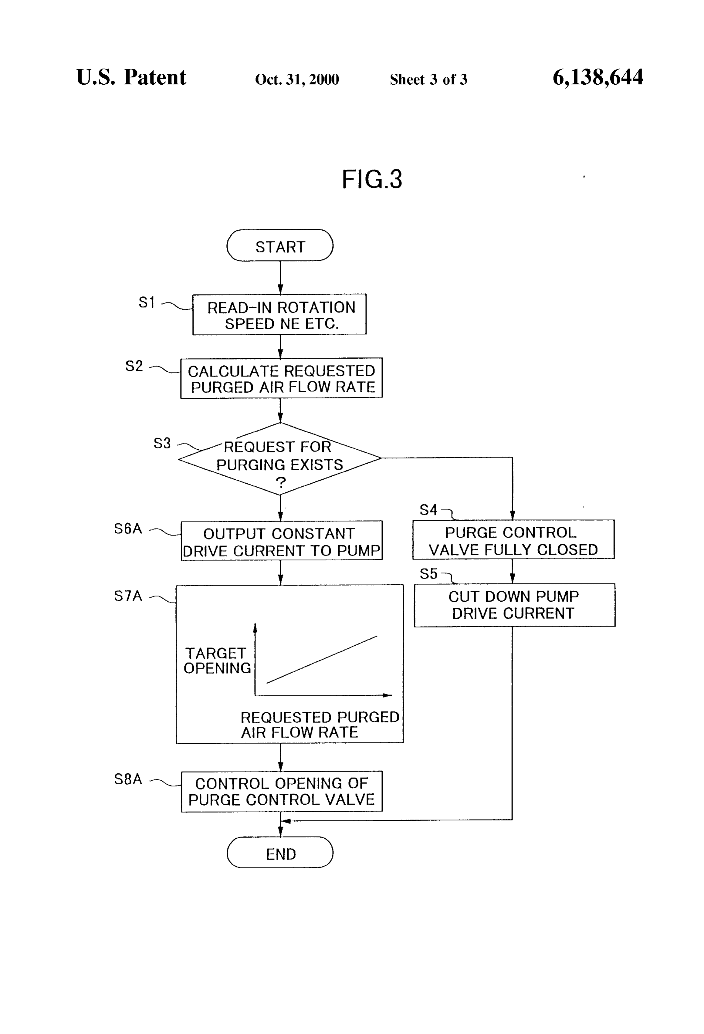
air of the engine 1, a crank angle Sensor 9 for detecting the However, it is also possible to control the purged air flow crank angle, a water temperature Sensor 10 for detecting a rate by controlling the opening of the purge control valve 17 temperature of the cooling water and the like are mounted while providing a constant drive current to the pump 18. thereto as the various Sensors. Further, the engine rotation The flowchart of FIG. 3 shows an embodiment of con Speed NE is calculated based on a detection Signal from the trolling the purged air flow rate by adjusting the opening of crank angle Sensor 9. the purge control valve 17 as mentioned above. Only S6A, On the other hand, a fuel vapor processing apparatus 11 S7A and S8A differ from the flowchart of FIG. 2. is equipped on the engine 1. The fuel vapor processing apparatus 11 adsorbs and collects fuel vapor generated When it is judged that a request for purging the canister inside a fuel tank 13 by an adsorbent of activated carbon and exists in S3, then the procedure is advanced to S6A, where the like filled inside a canister 12, purges the fuel adsorbed a constant drive current Set in advance is output to the pump by the adsorbent, and Supplies the purged air into the intake 18.
air passage of the engine 1 through a purge passage 14. The In the next step S7A, a target opening of the purge control purge passage 14 is communicated to an intake air passage Valve 17 is determined based on the requested purged air 20 on the upstream Side of the compressor 2. 15 flow rate.
The fuel vapor inside the fuel tank 13 is introduced to the Then, in S8A, the opening of the purge control valve 17 canister 12 through a fuel vapor passage 16 equipped with is controlled to the target opening. The opening control of a check valve 15 which is set to be opened when the pressure the purge control valve 17 may be performed for example by inside the fuel tank 13 is raised to a predetermined value or controlling the duty of the power Supplied to an electromag OC. netic coil.
Moreover, the purge passage 14 is equipped, in the order In the above, a turboSupercharger was equipped to the from the upstream to the downstream, with an engine electromagnetic-type purge control valve 17 and an electri equippedas with the Supercharger. However, the engine may be a mechanically driven Supercharger. For cally powered pump 18. When a drive current is applied to example, in an engine equipped with a mechanically driven the electrically powered pump 18 while the purge control 25
Valve 17 is at an opened State, the fuel vapor captured by the Supercharger whose compressor is positioned on the down canister 12 is Sucked together with new air by the electrically Stream Side of the throttle valve, the purged air may be powered pump 18, and Supplied to the intake air passage 20 Supplied portion to the upstream Side of the compressor, and the where the purged air is Supplied may either be on the on the upstream Side of the compressor 2.
AS above, the Supply of purged air may be per formed as long as it isoronthethedownstream upstream Side upstream
Side of the throttle valve,
Side of the compressor.
even during the Supercharged States by adopting the Struc ture to Supply the purged air to the intake passage 20 on the Moreover, the purge control valve 17 is not limited to an upstream side of the compressor 2, and even further, by electromagnetic-type valve, but may be driven to open and adopting the Structure to Supply the purged air forcibly by close by a Step motor and the like.
the electrically powered pump 18, the flow rate of the purged 35 What we claimed are:
air may be controlled relatively accurately even when the 1. A fuel vapor processing apparatus in an internal com preSSure inside the intake passage 20 on the upstream Side of bustion engine equipped with a Supercharger comprising a the compressor 2 is varied. compressor mounted in an intake air passage, Said fuel vapor Now, the control of the flow rate of the purged air by the 40 processing apparatus comprising:
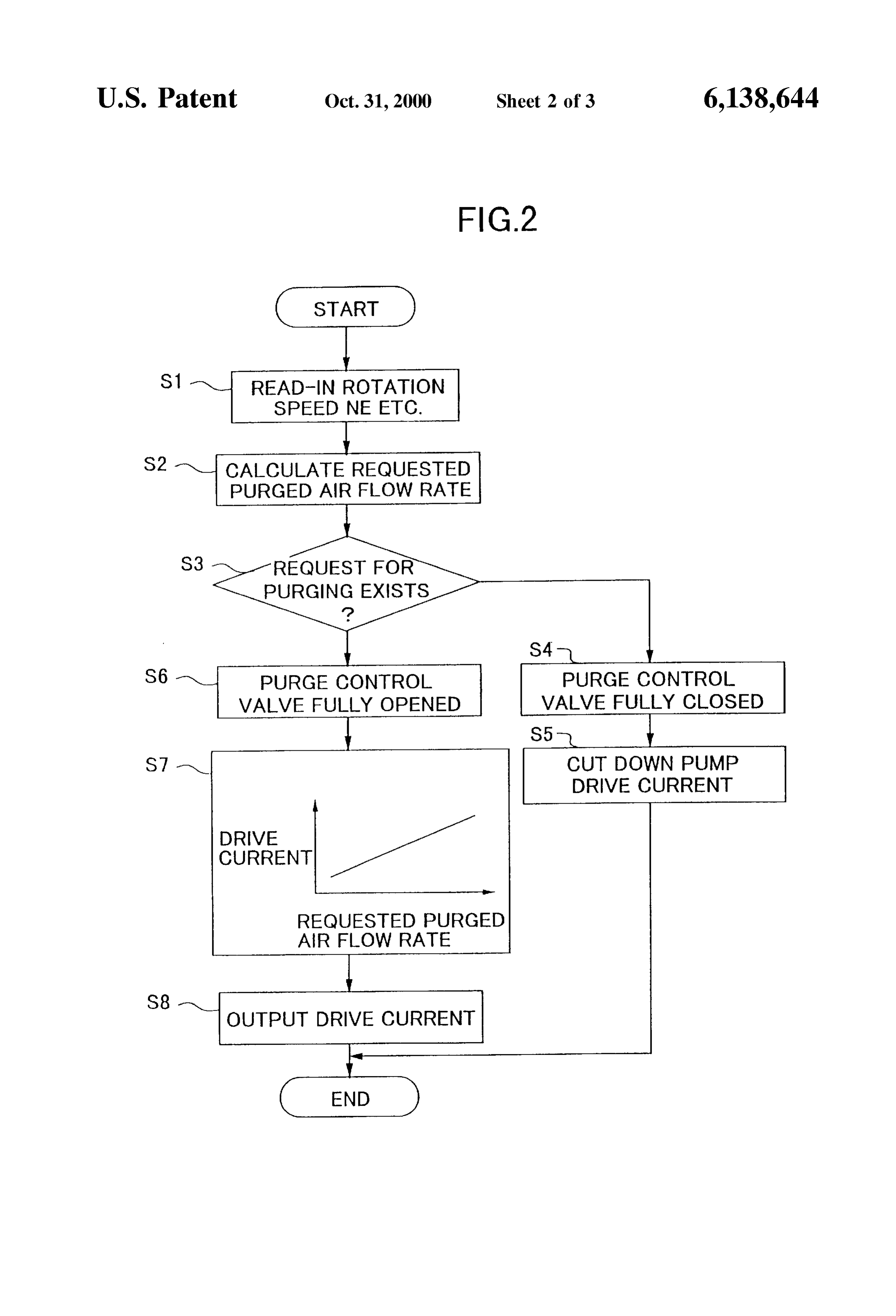
control unit 6 according to the above-mentioned Structure is a canister for adsorbing fuel vapor being generated in a explained according to the flowchart of FIG. 2. In the present fuel tank;
embodiment, as shown in the flowchart of FIG. 2, the control a purge passage for communicating Said canister to Said unit 6 is equipped with a function as the flow rate control intake air passage on the upstream Side of Said com device. preSSor; and
According to the flowchart of FIG. 2, in S1, the driving a pump mounted in the middle of Said purge passage. conditions Such as engine rotation Speed NE, the intake air 2. A fuel vapor processing apparatus in an internal com flow rate, the water temperature and the like are read in. bustion engine equipped with a Supercharger according to In S2, a requested purged air flow rate is calculated based claim 1, wherein Said pump is an electrically powered pump, on the driving conditions read in at S1. 50 and Said processing apparatus is further equipped with a In S3, a judgment is made on whether the request for flow rate control means for controlling a flow rate of purged purging the canister exists or not, based on whether the air by controlling a drive current being Supplied to Said requested purged air flow rate is Zero or not. When there is electrically powered pump.
no request for purging the canister, the procedure is 3. A fuel vapor processing apparatus in an internal com advanced to S4, where the purge control valve 17 is con 55 bustion engine equipped with a Supercharger according to trolled to be fully closed. In S5, the Supply of drive current claim 1, wherein Said pump is an electrically powered pump, to the pump 18 is stopped. Saidpurge passage is equipped with a purge control valve for On the other hand, when it is judged in S3 that the request controlling the opening of Said purge passage, and Said for purging the canister exists, then the procedure is processing apparatus is further equipped with a flow rate advanced to S6, where the purge control valve 17 is con 60 control means for controlling a flow rate of purged air by trolled to be fully opened. In S7, the drive current to the controlling the opening of Said purge control valve while pump 18 is determined based on the requested purged air controlling a drive current being Supplied to Said electrically flow rate. powered pump to a constant value. In S8, the drive current determined at S7 is output to the 4. A method of processing fuel vapor in an internal pump 18. 65 combustion engine equipped with a Supercharger compris In the above Structure, the purged air flow rate is con ing a compressor mounted in an intake air passage, com trolled according to the drive current applied to the pump 18. prising the Steps of

Page 7
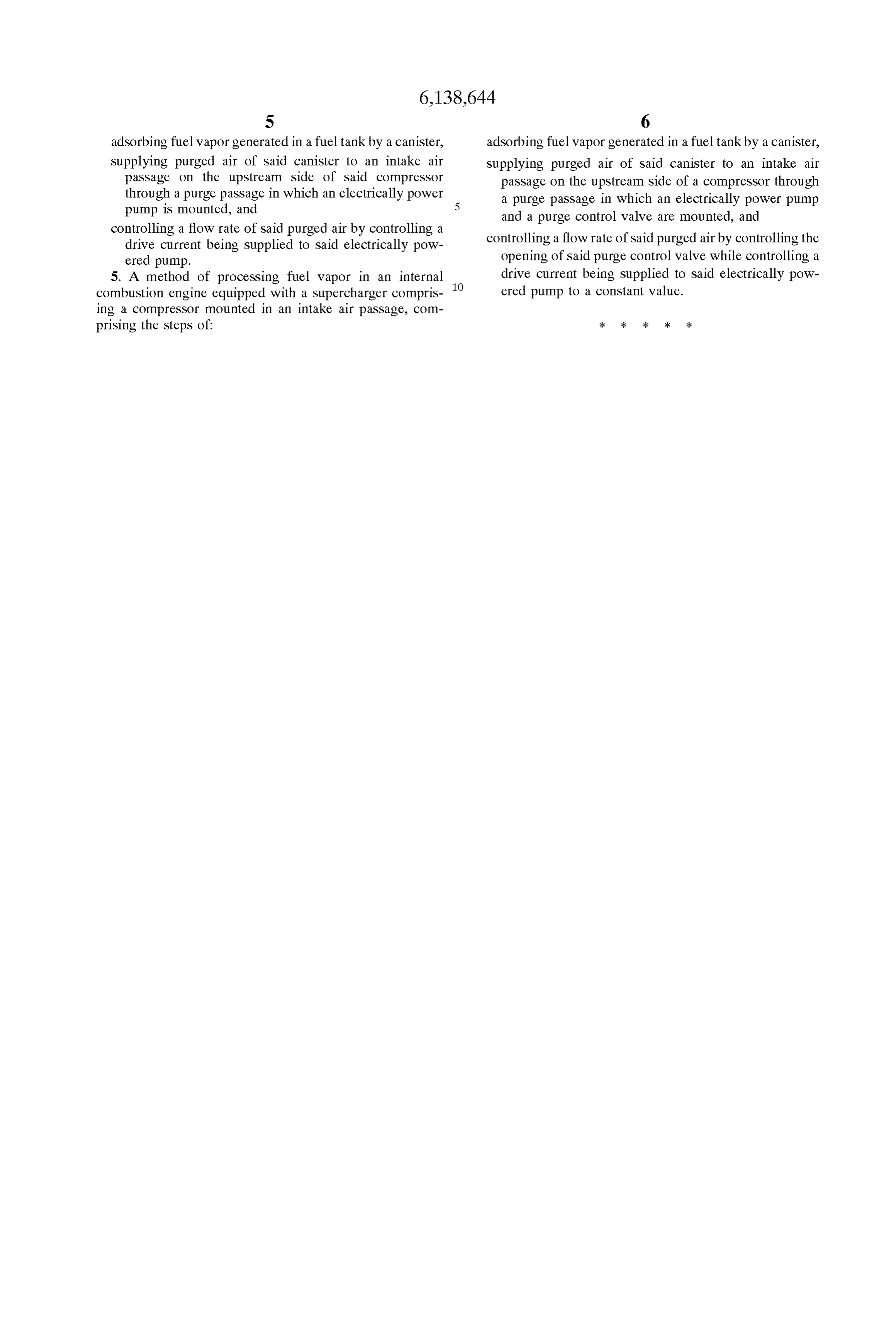
S 6 adsorbing fuel Vapor generated in a fuel tank by a canister, adsorbing fuel vapor generated in a fuel tank by a canister, Supplying purged air of Said canister to an intake air Supplying purged air of Said canister to an intake air passage on the upstream Side of Said compressor passage on the upstream Side of a compressor through through a purge passage in which an electrically power a purge passage in which an electrically power pump
and a purge control valve are mounted, and controlling a flow rate of Said purged air by controlling a controlling a flow rate of Said purged airby controlling the drive current being Supplied to Said electrically pow ered pump. opening of Said purge control valve while controlling a 5. A method of processing fuel vapor in an internal drive current being Supplied to Said electrically pow combustion engine equipped with a Supercharger compris ered pump to a constant value. ing a compressor mounted in an intake air passage, com prising the Steps of k k k k k
Page 8
UNITED STATES PATENT AND TRADEMARK OFFICE
CERTIFICATE OF CORRECTION
PATENT NO. : 6,138,644 Page 1 of 1
INVENTOR(S) : Masayuki Saruwatarietal.
It is certified that error appears in the above-identified patent and that said Letters Patent is hereby corrected as shown below:
Title page,
Item 30, Foreign Application Priority delete “Sept. 12, 1997 JP Japan
Signed and Sealed this
Ninth Day of July, 2002
Attest.
JAMES E ROGAN
Attesting Officer Director of the United States Patent and Trademark Office
Provenance
- Collection
- Cited prior art
- Original PDF
- patentimages.storage.googleapis.com →
- Filed
- 1998-11-25
- Pages
- 8
- Method
- pdftotext (the PDF's own text layer) + pdftoppm 300dpi page scans
- Source
- Google Patents bibliographic record
- Granted
- 2000-10-31
- Inventors
- Masayuki Saruwatari; Junichi Furuya; Unisia Jecs Corp
- Transcribed from
- patentimages.storage.googleapis.com →