patent · US3211255
Oil mist generator
12 October 1965
Page 1
Drawing sheet — no readable text.
Page 2
Drawing sheet — no readable text.
Page 3
Drawing sheet — no readable text.
Page 4
United States Patent Office 3,211,255 Patented Oct. 12, 1965
3,211,255 invention, the outline of the piping ssytem, in which the
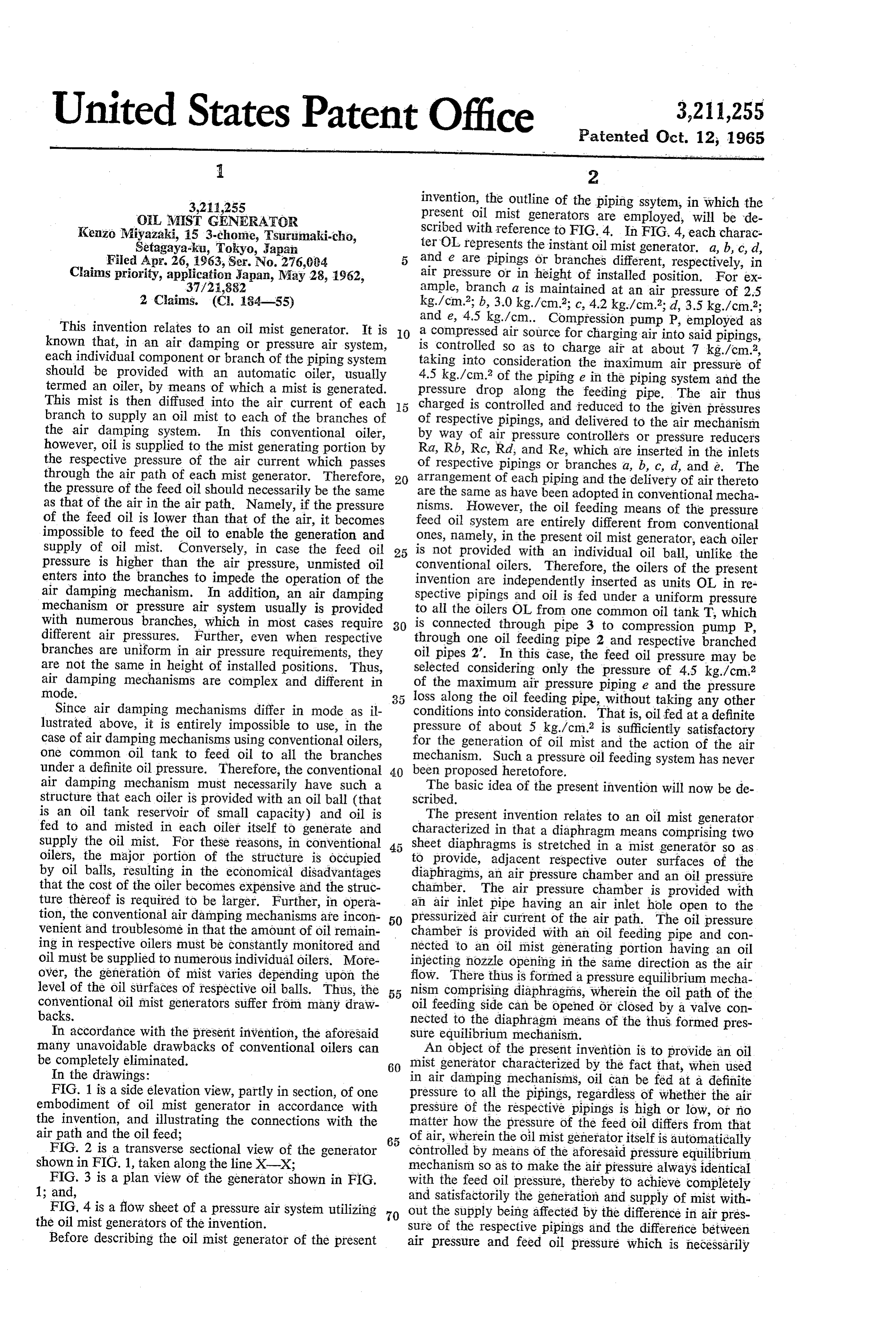
OL (VIST GENERATOR present oil mist generators are employed, will be de Kenzo Miyazaki, 15 3-chome, Tsurumaki-cho, scribed with reference to FIG. 4. In FIG. 4, each charac Setagaya-ku, Tokyo, Japan terOL represents the instant oil mist generator. a, b, c, d, Filed Apr. 26, 1963, Ser. No. 276,004 and e are pipings or branches different, respectively, in Claims priority, application Japan, May 28, 1962, air pressure or in height of installed position. For ex 37/21,882 ample, branch a is maintained at an air pressure of 2.5 2 Claims. (C. 184-55) kg./cm.; b, 3.0 kg/cm2; c, 4.2 kg/cm2; d, 3.5 kg./cm2; and e, 4.5 kg./cm. Compression pump P, employed as
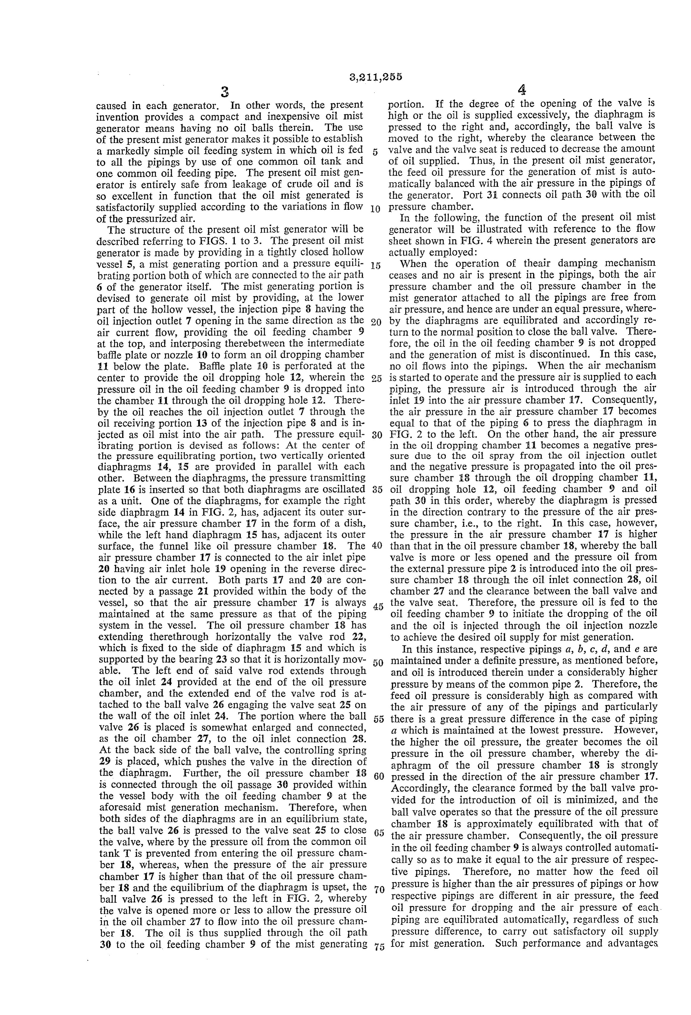
This invention relates to an oil mist generator. It is O a compressed air source for charging air into said pipings, known that, in an air damping or pressure air system, is controlled so as to charge air at about 7 kg./cm2, each individual component or branch of the piping system taking into consideration the maximum air pressure of should be provided with an automatic oiler, usually 4.5 kg./cm.* of the piping e in the piping system and the termed an oiler, by means of which a mist is generated. pressure drop along the feeding pipe. The air thus This mist is then diffused into the air current of each 15 charged is controlled and reduced to the given pressures branch to supply an oil mist to each of the branches of of respective pipings, and delivered to the air mechanism the air damping system. In this conventional oiler, by Way of air pressure controllers or pressure reducers however, oil is supplied to the mist generating portion by Ra, Rb, RC, Ra, and Re, which are inserted in the inlets the respective pressure of the air current which passes of respective pipings or branches a, b, c, d, and e. The through the air path of each mist generator. Therefore, 20 arrangement of each piping and the delivery of air thereto the pressure of the feed oil should necessarily be the same are the same as have been adopted in conventional mecha as that of the air in the air path. Namely, if the pressure nisms. However, the oil feeding means of the pressure of the feed oil is lower than that of the air, it becomes feed oil system are entirely different from conventional impossible to feed the oil to enable the generation and ones, namely, in the present oil mist generator, each oiler supply of oil mist. Conversely, in case the feed oil 25 is not provided with an individual oil ball, unlike the pressure is higher than the air pressure, unmisted oil conventional oilers. Therefore, the oilers of the present enters into the branches to impede the operation of the invention are independently inserted as units OL in re air damping mechanism. In addition, an air damping Spective pipings and oil is fed under a uniform pressure mechanism or pressure air system usually is provided to all the oilers OL from one common oil tank T, which with numerous branches, which in most cases require 30 is connected through pipe 3 to compression pump P, different air pressures. Further, even when respective branches are uniform in air pressure requirements, they through one oil feeding pipe 2 and respective branched oil pipes 2. In this case, the feed oil pressure may be are not the same in height of installed positions. Thus, Selected considering only the pressure of 4.5 kg./cm2 air damping mechanisms are complex and different in of the maximum air pressure piping e and the pressure mode. loss along the oil feeding pipe, without taking any other Since air damping mechanisms differ in mode as il conditions into consideration. That is, oilfed at a definite lustrated above, it is entirely impossible to use, in the pressure of about 5 kg/cm2 is sufficiently satisfactory case of air damping mechanisms using conventional oilers, for the generation of oil mist and the action of the air one common oil tank to feed oil to all the branches mechanism. Such a pressure oil feeding system has never under a definite oil pressure. Therefore, the conventional 40 been proposed heretofore.
air damping mechanism must necessarily have such a The basic idea of the present invention will now be de structure that each oiler is provided with an oil ball (that scribed. - is an oil tank reservoir of small capacity) and oil is The present invention relates to an oil mist generator fed to and misted in each oiler itself to generate and characterized in that a diaphragm means comprising two supply the oil mist. For these reasons, in conventional oilers, the major portion of the structure is occupied tosheetprovide, diaphragms is stretched in a mist generator so as adjacent respective outer surfaces of the by oil balls, resulting in the economical disadvantages diaphragms, an air pressure chamber and an oil pressure that the cost of the oiler becomes expensive and the struc chamber. The air pressure chamber is provided with ture thereof is required to be larger. Further, in opera an air inlet pipe having an air inlet hole open to the tion, the conventional air damping mechanisms are incon 50 pressurized air current of the air path. The oil pressure venient and troublesome in that the amount of oil remain chamber is provided with an oil feeding pipe and con ing in respective oilers must be constantly monitored and nected to an oil mist generating portion having an oil oil must be supplied to numerous individual oilers. More injecting nozzle opening in the same direction as the air over, the generation of mist varies depending upon the flow. There thus is formed a pressure equilibrium mecha level of the oil surfaces of respective oil balls. Thus, the 55 nism comprising diaphragms, wherein the oil path of the conventional oil mist generators suffer from many draw oil feeding side can be opened or closed by a valve con backs. nected to the diaphragm means of the thus formed pres In accordance with the present invention, the aforesaid sure equilibrium mechanism.
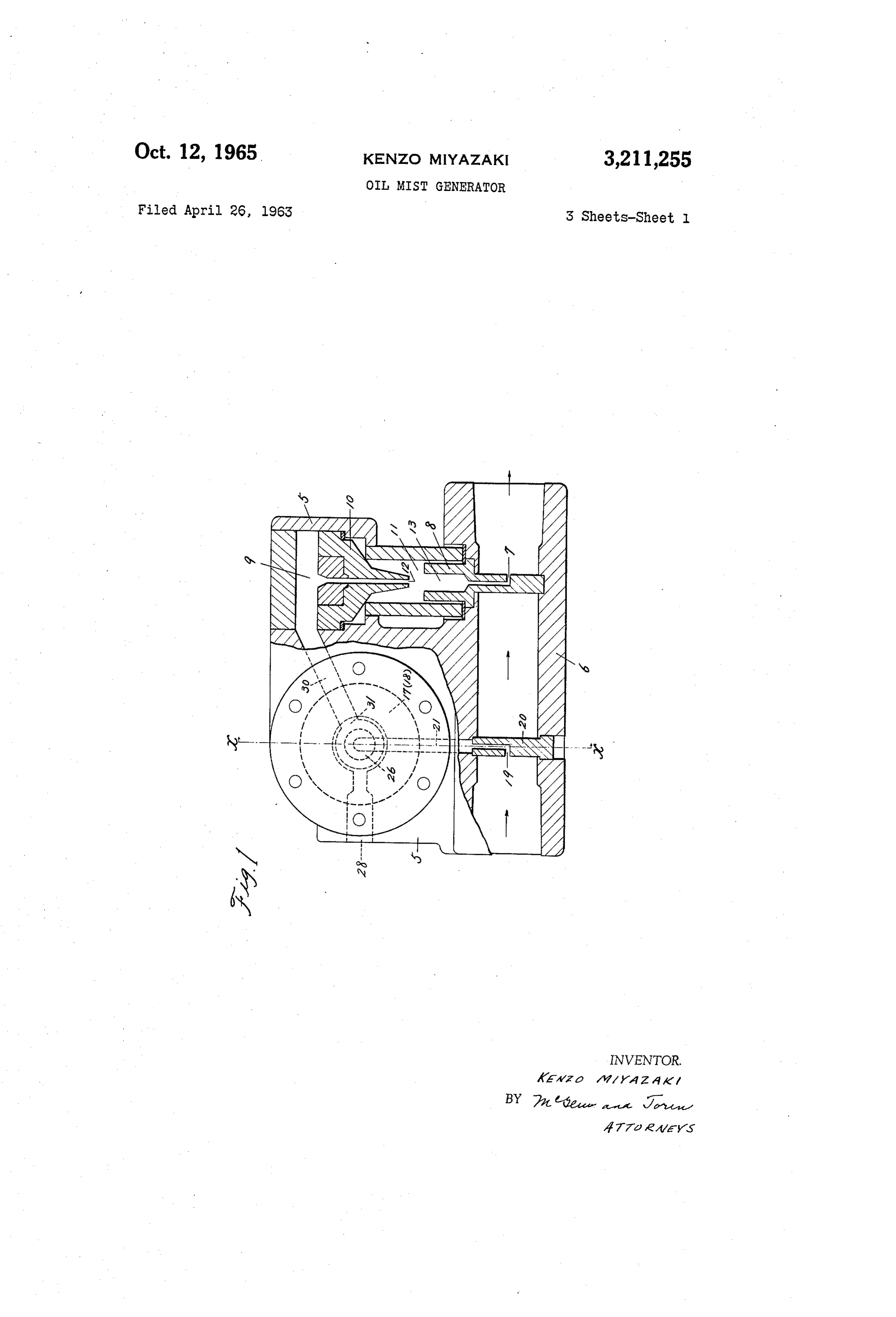
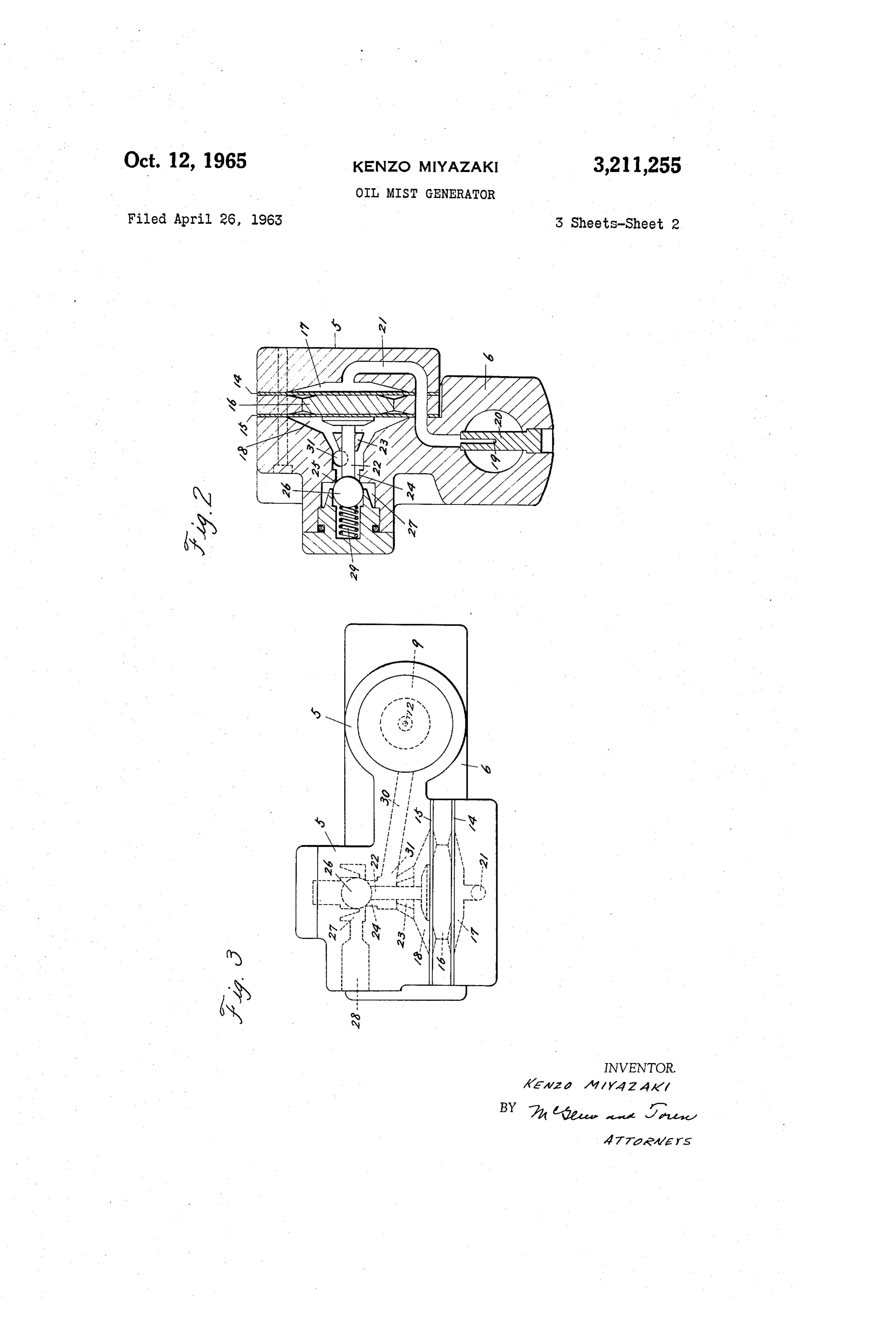
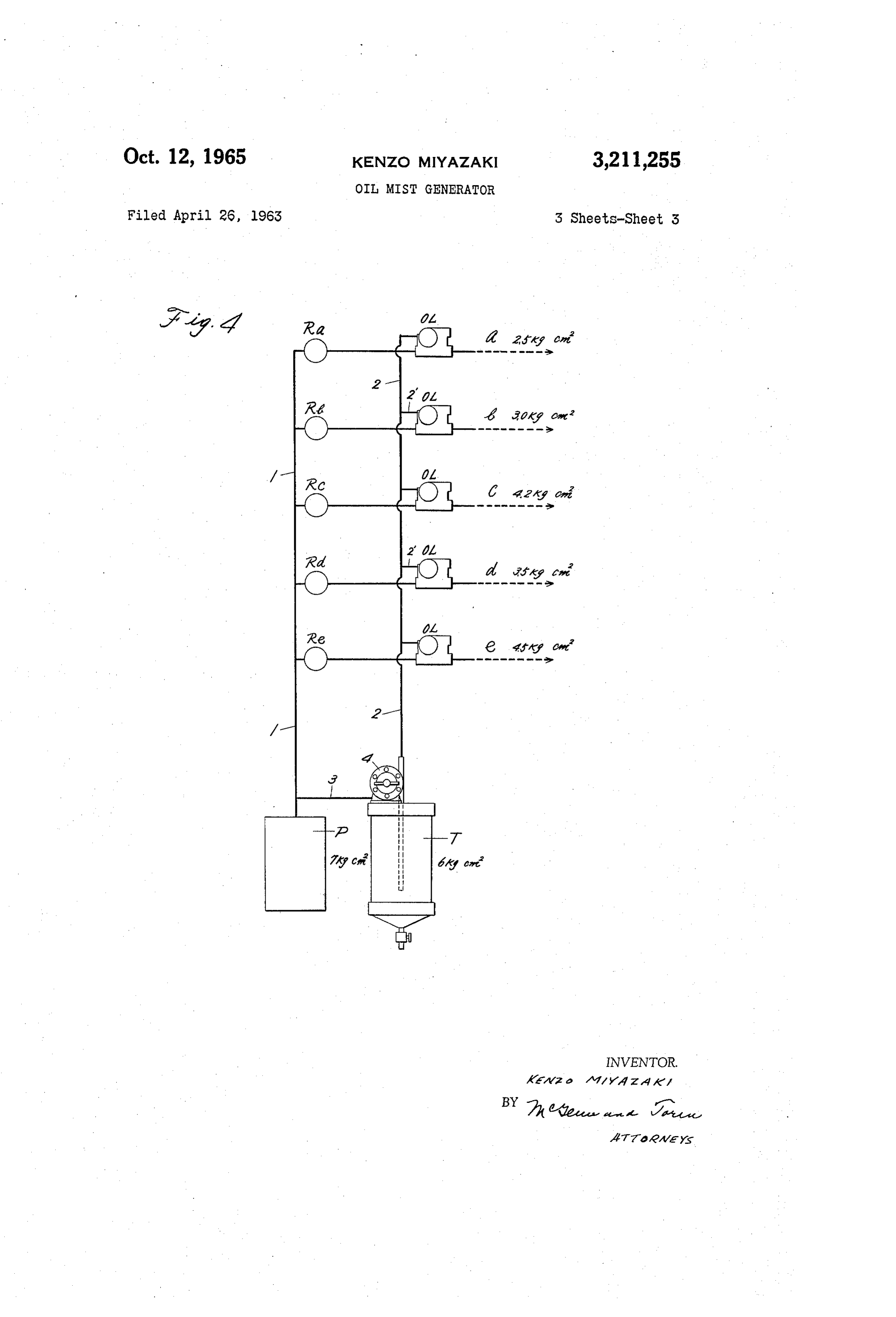
many unavoidable drawbacks of conventional oilers can An object of the present invention is to provide an oil be completely eliminated. 60 mist generator characterized by the fact that, when used In the drawings: in air damping mechanisms, oil can be fed at a definite F.G. 1 is a side elevation view, partly in section, of one pressure to all the pipings, regardless of whether the air embodiment of oil mist generator in accordance with pressure of the respective pipings is high or low, or no the invention, and illustrating the connections with the matter how the pressure of the feed oil differs from that air path and the oil feed; 85 of air, wherein the oil mist generator itself is automatically FIG. 2 is a transverse sectional view of the generator controlled by means of the aforesaid pressure equilibrium shown in FIG. 1, taken along the line X-X;
FIG. 3 is a plan view of the generator shown in FIG. with the feedso oil mechanism as to make the air pressure always identical pressure, thereby to achieve completely 1; and, and satisfactorily the generation and supply of mist with FIG. 4 is a flow sheet of a pressure air system utilizing 70 out the supply being affected by the difference in air pres the oil mist generators of the invention. sure of the respective pipings and the difference between Before describing the oil mist generator of the present air pressure and feed oil pressure which is necessarily
Page 5
caused in each generator. In other words, the present portion. If the degree of the opening of the valve is invention provides a compact and inexpensive oil mist high or the oil is supplied excessively, the diaphragm is generator means having no oil balls therein. The use pressed to the right and, accordingly, the ball valve is of the present mist generator makes it possible to establish moved to the right, whereby the clearance between the a markedly simple oil feeding system in which oil is fed 5 valve and the valve seat is reduced to decrease the amount to all the pipings by use of one common oil tank and of oil supplied. Thus, in the present oil mist generator, one common oil feeding pipe. The present oil mist gen the feed oil pressure for the generation of mist is auto erator is entirely safe from leakage of crude oil and is matically balanced with the air pressure in the pipings of so excellent in function that the oil mist generated is the generator. Port 31 connects oil path 30 with the oil satisfactorily supplied according to the variations in flow IO pressure chamber.
of the pressurized air. In the following, the function of the present oil mist The structure of the present oil mist generator will be generator will be illustrated with reference to the flow described referring to FIGS. 1 to 3. The present oil mist sheet shown in FIG. 4 wherein the present generators are generator is made by providing in a tightly closed hollow actually employed:
vessel 5, a mist generating portion and a pressure equili 5 When the operation of theair damping mechanism brating portion both of which are connected to the air path ceases and no air is present in the pipings, both the air 6 of the generator itself. The mist generating portion is pressure chamber and the oil pressure chamber in the devised to generate oil mist by providing, at the lower mist generator attached to all the pipings are free from part of the hollow vessel, the injection pipe 8 having the air pressure, and hence are under an equal pressure, where oil injection outlet 7 opening in the same direction as the 20 by the diaphragms are equilibrated and accordingly re air current flow, providing the oil feeding chamber 9 turn to the normal position to close the ball valve. There at the top, and interposing therebetween the intermediate fore, the oil in the oil feeding chamber 9 is not dropped baffle plate or nozzle 10 to form an oil dropping chamber and the generation of mist is discontinued. In this case, 11 below the plate. Baffle plate 10 is perforated at the no oil flows into the pipings. When the air mechanism center to provide the oil dropping hole 2, wherein the 25 is started to operate and the pressure air is supplied to each pressure oil in the oil feeding chamber 9 is dropped into piping, the pressure air is introduced through the air the chamber 11 through the oil dropping hole i2. There inlet 59 into the air pressure chamber 17. Consequently, by the oil reaches the oil injection outlet 7 through the the air pressure in the air pressure chamber 17 becomes oil receiving portion 13 of the injection pipe 8 and is in equal to that of the piping 6 to press the diaphragm in jected as oil mist into the air path. The pressure equil 30 FIG. 2 to the left. On the other hand, the air pressure ibrating portion is devised as follows: At the center of in the oil dropping chamber ill becomes a negative pres the pressure equilibrating portion, two vertically oriented sure due to the oil spray from the oil injection outlet diaphragms 4, 5 are provided in parallel with each and the negative pressure is propagated into the oil pres other. Between the diaphragms, the pressure transmitting sure chamber 8 through the oil dropping chamber 1, plate 6 is inserted so that both diaphragms are oscillated 35 oil dropping hole 12, oil feeding chamber 9 and oil as a unit. One of the diaphragms, for example the right path 30 in this order, whereby the diaphragm is pressed side diaphragm 14 in FIG. 2, has, adjacent its outer Sur in the direction contrary to the pressure of the air pres face, the air pressure chamber 7 in the form of a dish, sure chamber, i.e., to the right. In this case, however, while the left hand diaphragm 15 has, adjacent its outer the pressure in the air pressure chamber 17 is higher surface, the funnel like oil pressure chamber 18. The 40 than that in the oil pressure chamber 8, whereby the ball air pressure chamber 17 is connected to the air inlet pipe valve is more or less opened and the pressure oil from 20 having air inlet hole 9 opening in the reverse direc the external pressure pipe 2 is introduced into the oil pres tion to the air current. Both parts 7 and 20 are con sure chamber 8 through the oil inlet connection 28, oil nected by a passage 2 provided within the body of the chamber 27 and the clearance between the ball valve and vessel, so that the air pressure chamber 17 is always 45 the valve seat. Therefore, the pressure oil is fed to the maintained at the same pressure as that of the piping oil feeding chamber 9 to initiate the dropping of the oil system in the vessel. The oil pressure chamber 18 has and the oil is injected through the oil injection nozzle extending therethrough horizontally the valve rod 22, to achieve the desired oil supply for mist generation. which is fixed to the side of diaphragm S5 and which is In this instance, respective pipings a, b, c, d, and e are supported by the bearing 23 so that it is horizontally mov 50 maintained under a definite pressure, as mentioned before, able. The left end of said valve rod extends through and oil is introduced therein under a considerably higher the oil inlet 24 provided at the end of the oil pressure pressure by means of the common pipe 2. Therefore, the chamber, and the extended end of the valve rod is at feed oil pressure is considerably high as compared with tached to the ball valve 26 engaging the valve seat 25 on the air pressure of any of the pipings and particularly the wall of the oil inlet 24. The portion where the ball there is a great pressure difference in the case of piping valve 26 is placed is somewhat enlarged and connected, a which is maintained at the lowest pressure. However, as the oil chamber 27, to the oil inlet connection 28. the higher the oil pressure, the greater becomes the oil At the back side of the ball valve, the controlling spring pressure in the oil pressure chamber, whereby the di 29 is placed, which pushes the valve in the direction of aphragm of the oil pressure chamber 8 is strongly the diaphragm. Further, the oil pressure chamber 18 60 pressed in the direction of the air pressure chamber 17. is connected through the oil passage 30 provided within Accordingly, the clearance formed by the ball valve pro the vessel body with the oil feeding chamber 9 at the vided for the introduction of oil is minimized, and the aforesaid mist generation mechanism. Therefore, when ball valve operates so that the pressure of the oil pressure both sides of the diaphragms are in an equilibrium state, chamber 18 is approximately equilibrated with that of the ball valve 26 is pressed to the valve seat 25 to close 65 the air pressure chamber. Consequently, the oil pressure the valve, where by the pressure oil from the common oil in the oil feeding chamber 9 is always controlled automati tank T is prevented from entering the oil pressure cham cally so as to make it equal to the air preSSure of respec ber 18, whereas, when the pressure of the air pressure chamber 17 is higher than that of the oil pressure cham tive pipings. Therefore, no matter how the feed oil ber 18 and the equilibrium of the diaphragm is upset, the 70 pressure is higher than the air pressures of pipings or how ball valve 26 is pressed to the left in FIG. 2, whereby respective pipings are different in air pressure, the feed oil pressure for dropping and the air pressure of each.
the valve is opened more or less to allow the pressure oil piping in the oil chamber 27 to flow into the oil pressure cham are equilibrated automatically, regardless of such ber 18. The oil is thus supplied through the oil path pressure difference, to carry out satisfactory oil Supply 30 to the oil feeding chamber 9 of the mist generating for mist generation. Such performance and advantages
Page 6
of the present generator are excellent features which have Source of oil under pressure having a value such that the not been provided heretofore. oil supplied to each oil mist generator is at a pressure sub By virtue of the above functions and the high feed oil stantially equal to the highest of said branch line air pres pressure, the present oil mist generator is entirely free sures; and pressure responsive means in each oil mist of danger of oil leaks into the pipings. Even if the opera generator connected to the respective air branch line and tion of the air damping mechanism has stopped for some to the respective branch oil supply line and operable to reason and pressure air has remained therein, both air deliver an oil mist to the respective air branch line at a pressure chamber 17 and oil pressure chamber 18 are rate proportional to the air pressure in the respective air subjected to the same pressure of the air path, whereby branch line.
both chambers are equilibrated in pressure to close the O 2. In the combination claimed in claim 1, each oil ball valve 26. Therefore, even when the oil feeding is mist generator comprising a substantially sealed casing continued, no oil enters into the pipings. For the same means enclosing an interior cavity and formed with an reasons as above, even when numerous pipings are pro air flow passage included in the respective air branch vided in positions different in height, the effect of mist line, flexible diaphragm means dividing said cavity into generation is attained without any obstacle. 5 first and second chambers, means connecting the first To summarize, the present oil mist generator is marked chamber to the respective air branch passage at a first ly excellent and convenient because of the fact that even point therealong for application of the air pressure to when it is applied to complex air pipings different in mode, one side of said diaphragm, oil mist generator means con the oil pressure is automatically controlled in the mist necting the second chamber to the respective air branch generator itself so as to be suitable for respective pipings, 20 passage at a second point therealong downstream of said entirely regardless of environmental conditions, whereby first point; means connecting the respective branch oil a satisfactory oil feeding for mist generation is carried supply line to the second chamber for application of the out without danger from any leakage of oil. Accord oil pressure to the other side of the diaphragm means, ingly, the present generator requires no parts for indi normally closed check valve means between the respec vidual oil tanks, contrary to the case of conventional oilers, 25 tive branch oil supply line and the second chamber and whereby the cost of the oiler can be greatly lowered. blocking flow of oil to the second chamber, and valve Moreover, it is not necessary to monitor many oilers and operating means operatively connecting the diaphragm supply oil thereto, unlike the case where conventional oil means to the check valve means and effective to open ers are employed, so that the operation of the air damp the check valve means when the air pressure in the first ing mechanism is made markedly simple and convenient. 30 chamber exceeds the oil pressure in the second chamber. It should be said, therefore, that the present invention provides an excellent oil mist generator which is com References Cited by the Examiner pletely novel.
What I claim is: UNITED STATES PATENTS 1. In combination, a pressure air system, including a 35 1,356,166 10/20 Marsh ---------------- 184-56 source of air under pressure, a main supply line connected 1,907,464 5/33 Terry ----------------- 184-55 to said source, and plural branch lines each connected to 2,096,125 10/37 McDougall ------------ 251-24 said main supply line, each branch line operating at a 2,269,276 1/42 Lichtenstein ----------- 73-213 respective branch line pressure, and at least some of said 2,982,376 5/61 Lincoln --------------- 184-55 branch line pressures differing from others of said branch 40 3,023,849 3/62 Tine ----------------- 184-55 line pressures; plural oil mist generators each disposed in 3,040,835 6/62 Ahnert ---------------- 184-55 a respective branch line; a source of oil under pressure; 3,115,950 12/63 Malec ---------------- 184-55 an oil feed line connected to said source of oil under pres sure; branch oil supply lines each connecting said oil feed LAVERNE D. GEIGER, Primary Examiner. line to a respective oil mist generator; the pressure of said 4.5 MILTON KAUFMAN, Examiner.
Provenance
- Collection
- Cited prior art
- Original PDF
- patentimages.storage.googleapis.com →
- Filed
- 1963-04-26
- Pages
- 6
- Method
- pdftotext (the PDF's own text layer) + pdftoppm 300dpi page scans
- Source
- Google Patents bibliographic record
- Granted
- 1965-10-12
- Inventors
- Miyazaki Kenzo
- Transcribed from
- patentimages.storage.googleapis.com →