patent · US3762390
Oil-fired, infrared heater
2 October 1973
Page 1 — bibliographic record
United States Patent (19) 11 3,762,390 Mendelson 145 Oct. 2, 1973
(54) OIL-FIRED, INFRARED HEATER
76 Inventor: Ralph R. Mendelson, c/o The Glass
Lined Water Heater Co., 13000 An oil-fired infrared heater is disclosed including a Athens Ave., Cleveland Hits., Ohio conical, thin wall combustion chamber of high temper 44 107 ature refractory fiber removably disposed within and 22 Filed: Mar. 8, 1972 supported at its opposite ends by a cylindrical sheet metal housing. One end of the housing supports an oil 21 Appl. No.: 232,845 burner assembly by which oil and air are introduced into one end of the combustion chamber, and an aper 52 U.S. Cl................................ 126/92 R, 431/328 tured metal plate is disposed across the opposite end of 51 Int. Cl. .............................................. F24c 5/08 the chamber and is removably interconnected with the 58) Field of Search ........................ 126/92 R, 92 B; cylindrical housing. The apertures in the metal plate 431/328, 329 account for a very small percentage of the total area thereof, whereby a considerable amount of inner and 56) References Cited outer metal surface area exists about and between the
UNITED STATES PATENTS
plate apertures. During burner operation the chamber wall and the apertured plate are heated to incandes 3,561,422 2/1971 Colin-Smith.......................... 126/92 cence. The apertures in the plate allow products of FOREIGN PATENTS OR APPLICATIONS combustion to escape outwardly of the combustion 1,454,304 2/1969 Germany........................... 126/92 B chamber, and the inner and outer surface portions of 557,304 3/1960 Belgium............................ 126/92 R the plate respectively reflect heat back into the cham ber and radiate heat outwardly from the outer surface
Primary Examiner-William E. Wayner of the apertured plate.
Assistant Examiner-William E. Tapolcai, Jr. 10 Claims, 4 Drawing Figures Attorney-James H. Tilberry et al.
Page 2
Drawing sheet — no readable text.
Page 3
Drawing sheet — no readable text.
Page 4
Drawing sheet — no readable text.
Page 5
OIL-FIRED, INFRARED HEATER considerable surface area is available for reflecting The present invention relates to the art of infrared heat inwardly of a combustion chamber and radiating generators and more particularly, to a fuel-fired infra heat heat outwardly of the wall, whereby fuel burning and radiating efficiencies are increased.
red generator. An object of the present invention is the provision of Infrared heaters or generators have been provided a fuel-fired infrared generator which is inexpensive to heretofore for the purpose of radiating heat to an ob ject in the path of the output thereof without wasting produce and maintain.
Another heat on the air between the generator and the object to tor of the foregoing object is the provision of an infrared genera be heated. Such infrared generators are ideal for use in 10 number of parts structurally character comprised of a minimum buildings or outdoor areas where frequent air tempera assembly and disassembly interrelated to provide for thereof in a minimum ture changes occur. The heating of objects in areas of amount of time and with minimum effort. the latter character by other heating devices becomes A further object of the present invention is the provi extremely inefficient and ineffective due to the heating sion of an infrared generator of the foregoing character of the air between the heater and the object. 15 having structural characteristics providing for the unit Several factors affect the desirability and acceptance to be, selectively, portable or permanently installed and of infrared generators of the foregoing character. For to be adjustable relative to the support therefor. example, if a considerable number of such generators Yet another object of the present invention is the are required to perform a desired heating function provision of a fuel-air fired infrared generator including within a building or outdoors, it becomes desirable for 20 a combustion the units to be relatively inexpensive, readily and ad ated therewith chamber and having and an apertured wall associ inner and outer surface por justably mountable or positionable relative to the ob tions for respectively radiating heat outwardly of the ject or objects to be heated, inexpensive to maintain chamber and reflecting heat inwardly of the chamber. and efficient in operation both from the standpoint of Still another object of the present invention is the cost of operation and radiating efficiency. Further, with 25 provision of a liquid fuel-fired infrared generator in regard to fuel-fired infrared generators, it becomes de which a more complete burning of the fuel in the com sirable that combustion and burning of the fuel-air mix bustion chamber is achieved than heretofore possible. ture in the combustion chamber of the device be as complete as possible to reduce the exhaust of contami provision Yet another object of the present invention is the nates therefrom during operation thereof. of an infrared generator of the foregoing 30 character wherein the radiation of heat outwardly of
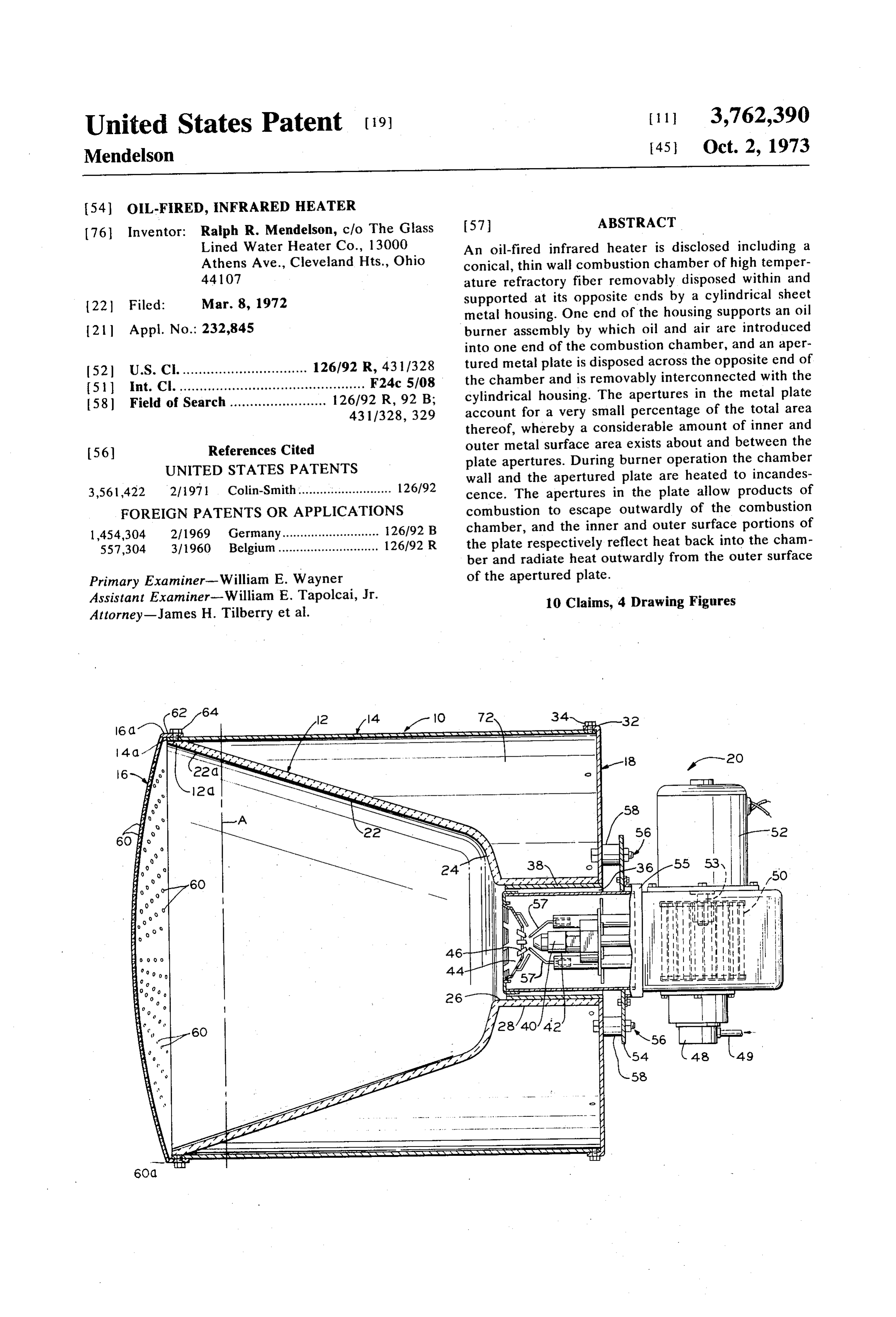
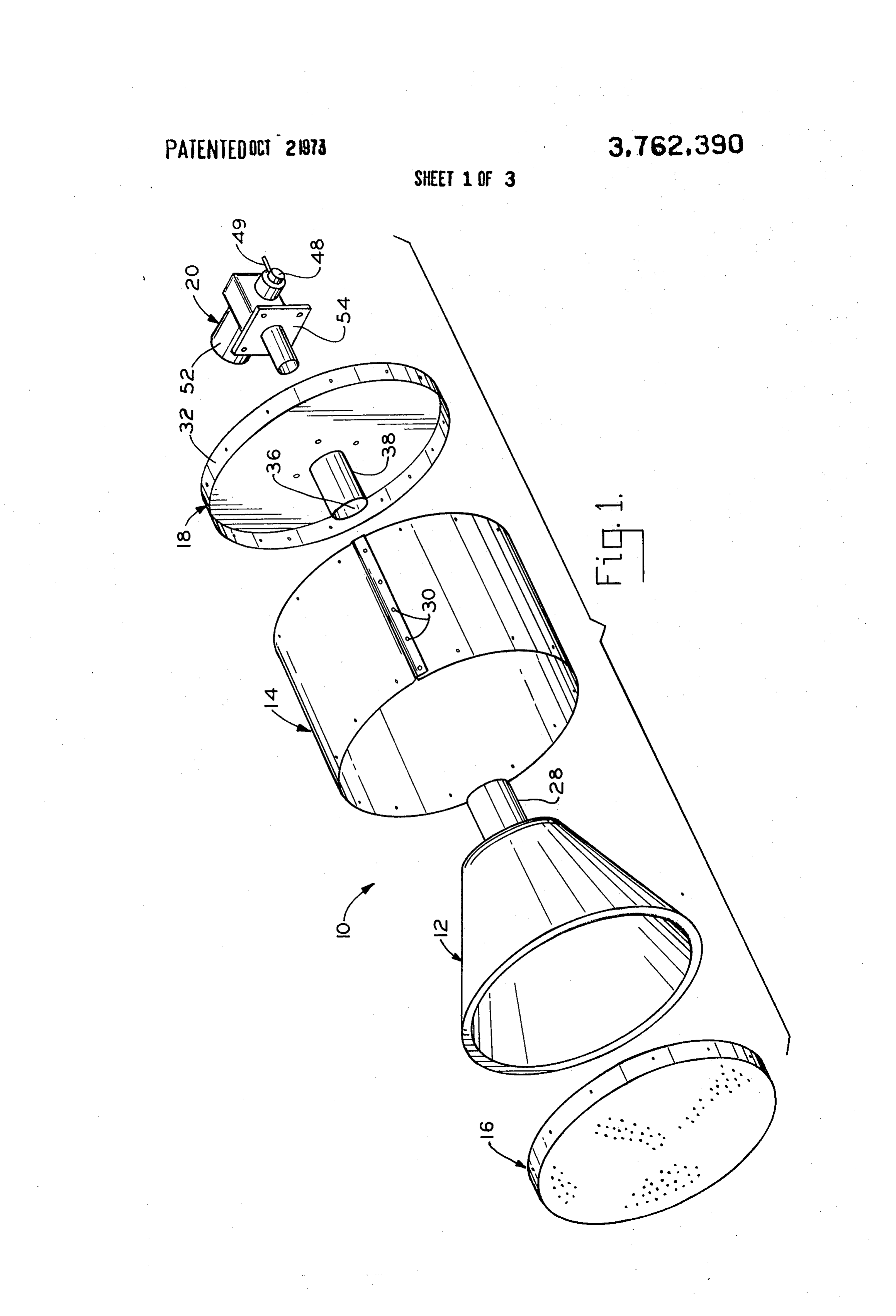
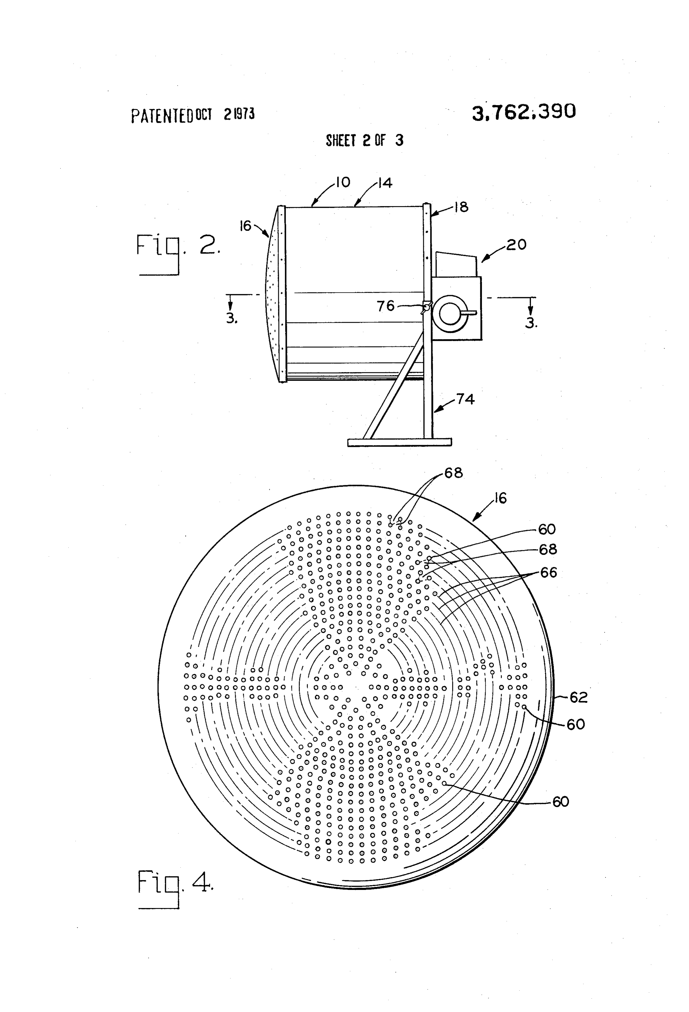
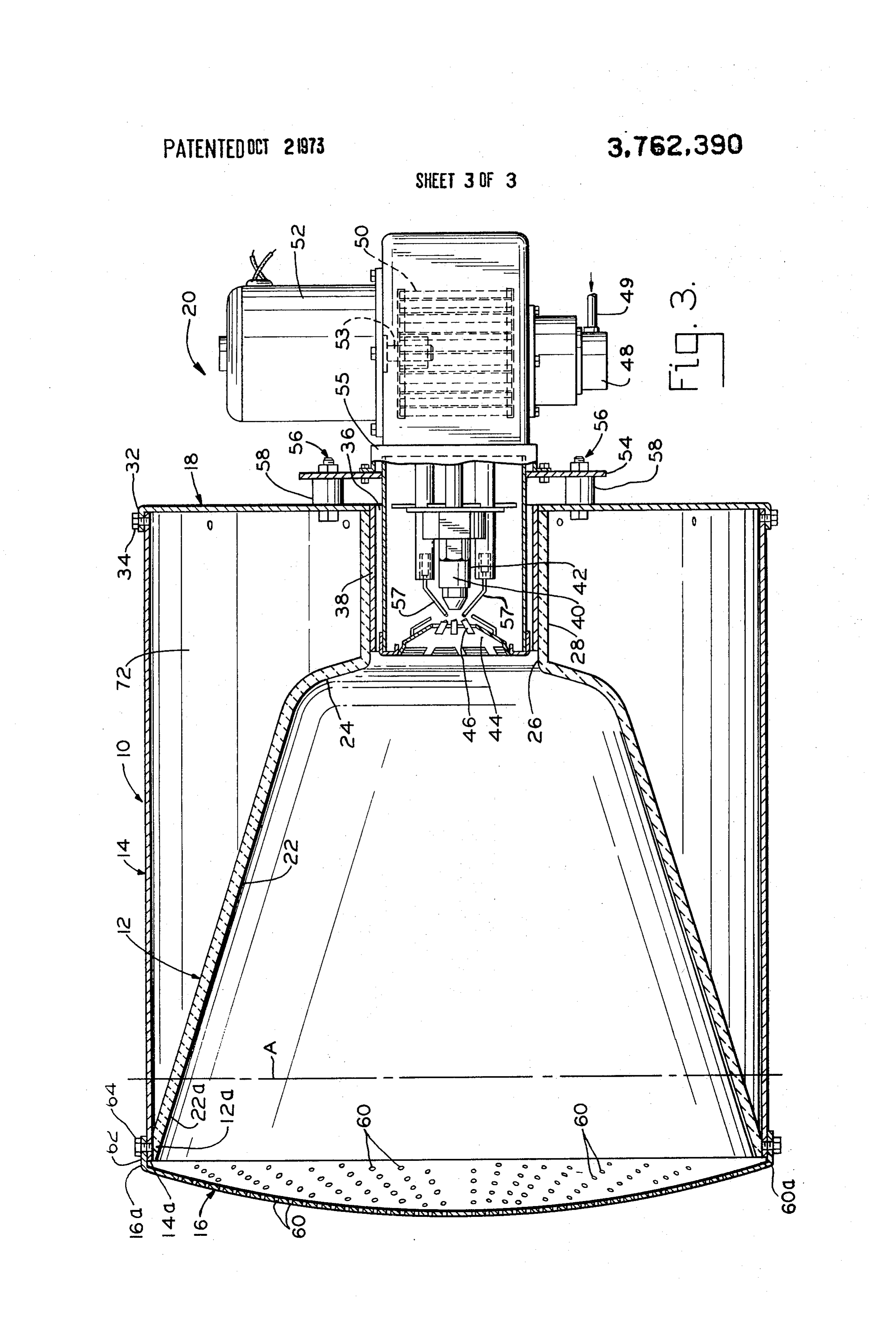
The present invention advantageously provides a liq uid fuel-fired infrared generator having the foregoing theThe chamber is greater than heretofore possible. foregoing objects, and others, will in part be ob desirable characteristics. In this respect, the generator vious and is comprised of a minimum of component part which conjunctionin part with more fully pointed out hereinafter in the description of the drawing in are of light-weight construction and which are structur 35 which:
ally interrelated in a manner whereby assembly and dis FIG. 1 is an exploded perspective view of the compo assembly thereof is achieved in a minimum amount of nents time and with a minimum of physical effort, all of made of in a preferred structure of an infrared generator accordance with the present invention;
which lends to a unit which is relatively inexpensive to produce and maintain and which, because of the light 40 erator FIG. 2 is a side elevation view of the assembled gen weight construction thereof, is readily portable, and is illustrating the generator mounted on a stand; easy to handle or manipulate during installation lustrated FIG. 3 is a plan view, in section, of the generator il thereof. in FIG. 2, the view being taken along line In accordance with another aspect of the present in 3-3 in FIG. 2; and vention, the structure of the generator provides for 45 ponent FIG. 4 is a plan view of the apertured end wall com greater fuel burning and heat radiating efficiencies than of the generator.
heretofore possible. In this respect, the generator in wherein Referring now to the drawing in greater detail cludes a combustion chamber adapted to receive a a preferred the showings are for the purpose of illustrating fuel-air mixture through one end thereof for burning for embodiment of the invention only and not the purpose therein, and an apertured end wall which extends 50 ator unit 10 is illustrated of limiting the same, an infrared gener across the other end of the combustion chamber. The which is comprised of a com bustion chamber apertured wall has an inner and outer surface relative metal housing member 14, housing component 12, a cylindrical sheet to the combustion chamber, each of which surfaces is nents 16 and 18, and a fuel burner unit end wall compo divided into generally planar surface portions disposed 20. between or around the apertures through the wall. The 55 Combustion chamber component 12 may be pro generally planar surface portions have a surface area duced from any suitable high temperature refractory many times greater than the area of an aperture material and may have any desired structural configu ration which will provide for an inner chamber surface through the wall. During operation of the generator, which converges from the outer end thereof toward the the combustion chamber and end wall are heated to in inner end of the chamber. In the embodiment illus candescence, and the inner surface portions of the end 60 trated the combustion chamber component is of thin wall reflect heat inwardly of the combustion chamber walled generally conical construction and has an inner to assure a more complete burning of the fuel within surface 22 which converges generally uniformly from the chamber than heretofore possible. The outer sur outer end 22a thereof toward the inner end of the face portions of the end wall radiate heat outwardly chamber. The inner end of the chamber component is from the end wall. Preferably, the total area of the ap 65 defined by a curved ertures through the end wall is between 1 to 5 percent 26 therethrough andwall portion 24 having an opening an integral cylindrical sleeve 28 of the total surface area of one of the inner and outer wall surfaces. It will be appreciated, therefore, that extending rearwardly from the opening for the purpose
Page 6
set forth more fully hereinafter. Preferably, combustion 44 having a central opening aligned with the fuel nozzle chamber component 12 is produced from a high tem and surrounded by a plurality of vanes 46 which direct perature refractory fiber material having an organic or air in a swirling pattern into the combustion chamber ceramic bonding agent therein and which is molded or to mix with and swirl the fuel in a circular path relative otherwise shaped to provide a generally conical, thin to the longitudinal axis of the combustion chamber. In wall chamber component in which the wall thickness is the illustrated embodiment, the fuel is oil and is deliv substantially uniform throughout. A suitable material ered to nozzle 40 by a pump component 48 of the fuel from which the combustion chamber component can air burner assembly 20. Pump 48 receives fuel from a be fabricated is marketed by Johns-Manville Company suitable source, not illustrated through line 49. Air is of Manville, NJ under the trademark CERA-FORM. 10 delivered through the air nozzle toward the combustion The latter material is extremely lightweight and heats chamber by a fan component 50 of the burner assembly to incandescence upon burning of a fuel-air mixture in 20, and fan 50 and pump 48 are driven by electric the combustion chamber. While surface portion 22 of motor 52 of assembly 20 through motor shaft means the combustion chamber preferably converges gener 53. Electrodes 57 are disposed adjacent the outlet end ally uniformly from the outer end thereof toward the 15 of nozzle 40 to provide for ignition of the fuel-air mix inner end of the chamber, it will be appreciated that the ture for burning in the combustion chamber, and it will inner surface of the chamber wall could be otherwise be appreciated that the electrodes are connected to a configured and could, for example, have an arcuate or suitable source of electrical power not illustrated. Fur curved contour in longitudinal cross section. ther, it will be appreciated that suitable controls can be Cylindrical housing component 14 is of thin gauge 20 provided as a part of the fuel air assembly to control sheet metal such as aluminized steel and is of substan operation of the various components thereof in re tially uniform diameter between the opposite ends sponse to the detection or failure to detect establish thereof. Preferably, component 14 is constructed by ment of a flame in the combustion chamber. Fuel-air forming a tube from a sheet metal blank and intercon burner unit 20 may be provided with any suitable sup necting the free ends of the blank by suitable fastener 25 port structure to facilitate removably mounting the as elements 30. It will be appreciated, however, that the sembly as a unit on end wall 18. For example, a support housing component could be otherwise constructed. plate 54 may be attached to the burner unit housing 55 Housing component 14 is of a longitudinal length cor in any suitable manner and removably interconnected responding substantially to the longitudinal length of with end wall 18 such as by nut and bolt assemblies 56. combustion chamber component 12, and is closed at Preferably, spacers 58 are interposed between plate 54 one end thereof by end wall 18. Wall 18 is a sheet metal and wall 18 to reduce heat transfer therebetween which component of aluminized steel or the like, and is pro might be detrimental to certain of the components of vided with a longitudinally extending peripheral flange the fuel-air assembly 20.
32 adapted to axially receive the corresponding end of 35 End wall 16 extends across the outer end of combus housing component 14. Suitable fastener elements such tion chamber component 12 and is provided with a as screws 34 serve to removably interconnect end wall multiplicity of apertures 60 extending therethrough. In 18 with the housing component. the preferred embodiment, end wall 16 is a thin, cylin Wall 18 is provided substantially centrally thereof drical plate of No. 22 gauge stainless steel having alon with a cylindrical opening 36 which is surrounded by a gitudinally extending peripheral flange 62 adapted to cylindrical metallic sleeve element 38 which projects 40 axially receive the corresponding end of housing com longitudinally inwardly of housing component 14 from ponent 14. Suitable fastener elements such as screws wall 18. Sleeve 38 may be integral with end wall 18 or 64 provide for end wall 16 to be removably intercon may be a separate component suitably attached nected with housing component 14. When end wall 16 thereto. Further, sleeve 38 has an outer diameter corre 45 and end wall 18 are interconnected with housing com sponding substantially to the inner diameter of cylindri ponent 14, it will be appreciated that these components cal sleeve portion 28 of combustion chamber compo cooperate to restrain any significant longitudinal move nent 12. This relationship provides for sleeve 38 to slid ment of the combustion chamber component 12 rela ably receive and support the inner end of the combus tive to housing component 14. It will be appreciated, of tion chamber component relative to wall 18 and hous 50 course, that either or both of the end walls 16 and 18 ing component 14. The outer end of the combustion could be interconnected with housing component 14 chamber component slidably engages and is supported by means other than the flange and fastener arrange by the corresponding end of housing component 14 ment illustrated. For example, housing component 14 which has an inner diameter, at least at the outer end could be provided at one or both of its end with radially 14a thereof, which corresponds substantially to the 55 outwardly or inwardly projecting peripheral flanges to outer diameter of outer end 12a of the combustion which the end walls could be secured. chamber. It will be appreciated that this structural rela Openings 60 preferably are cylindrical and of uni tionship provides for the combustion chamber compo form diameter and are generally uniformly spaced nents to be readily introduced into and removed from apart across end wall 16. The total area of the openings the housing as defined by housing component 14 and 60 60 is extremely small relative to the total surface area end wall 18 and to be supported laterally within the of each of the inner and outer surfaces of end wall 16. housing without the use of fastener elements or the In this respect, the total area of the openings is between like. from 1 to 5 percent of the total surface area of either Wall 18 also serves to support fuel-air burner unit 20 the inner or outer surface of the end wall within mar which, in the embodiment illustrated, includes a fuel 65 ginal edge 60a thereof. Within this range, a total area nozzle 40 and an air nozzle portion 42 disposed within of the openings of from about 1 percent to about 4 per sleeve 38 and adjacent the inner end of the combustion cent has been found most desirable. It will be appreci chamber. The air nozzle portion includes an end plate ated, therefore, that a surface area of from about 95 to
Page 7
S 6 99 percent of the total surface area of the end wall openings relative to each surface is approximately 8.69 plate is exposed to define reflecting and radiating sur square inches, or 2.29 percent of the total area. Thus, face portions respectively on the inner and outer sur approximately 97.7 percent of each of the inner and faces of the end wall. It will be further noted, that the outer surface areas are available for heat reflection and individual surface portions disposed between or sur heat radiation. Further, the unit has a longitudinal di rounding the openings are generally planar surfaces, mension including the burner unit of 26 % inches, and the total area of which is available for reflecting or radi a housing length of 18 inches. The unit is liquid fuel ating functions to be described more fully hereinafter. fired, burns approximately 1.0 gallons per hour, and Openings 60 may be provided in end wall 16 ran the burner unit is operable with fuel oil, kerosene, die domly or in a suitable pattern and, preferably, are pro O sel fuel or jet engine fuel, and has an input capacity of vided in the pattern illustrated in FIG. 4. In this respect, 140,000 btu per hour. The weight of the unit including a plurality of openings 60 are provided in each of a plu a mounting stand or bracket of the character described rality of radially spaced apart coaxial annular paths 66. herein, is approximately 64 pounds. In operation, with The circumferential spacing between adjacent open oil as the fuel, a flame temperature of about 2,500 F ings 60 in all of the paths 66 is substantially equal, and 15 exists inside the chamber. Preferably the pressure in the radial spacing between annular paths 66 is gener the combustion chamber is maintained between about ally uniform. It will be appreciated that this pattern 0.04 to 0.14 inches H.O. Further, the temperature of provides for more openings to be provided in one path the apertured end wall during operation of the genera 66 than in a radially inwardly adjacent path 66. This tor under these conditions is about 1,550 F. particular pattern provides for the individual surface 20 When a fuel-air mixture is introduced into and ig portions of the end wall lying between a circumferen nited to burn in combustion chamber component 12, tially adjacent pair of openings and an opening radially the combustion chamber component and wall 16 are adjacent one of the circumferentially adjacent pair to heated to incandescence. Openings 60 provide for be of generally equal area to one another throughout 25 products of combustion to escape from the combustion the total surface of the wall. Surface portions defined chamber and forwardly thereof. Heat is radiated to in the foregoing manner are designated by numerals 68 ward wall 16 from surface 22 of the combustion cham in FIG. 4, and it will be appreciated that these areas ber component and is reflected back into the combus exist on both the inner and outer surfaces of the end tion chamber toward the inner end thereof by the inner wall. Such areas could, of course, be otherwise defined 30 surface portions 68 of wall 16. Reflection of heat in this and the use of a triangular grouping of the openings is manner, together with the establishment of a pressure intended merely to demonstrate that the inner and within the chamber resulting from the small outlet area outer surfaces include surface portions between the defined by openings 60, serves to provide far more openings which are generally planar surfaces. The pre complete combustion than would otherwise be possi ferred pattern arrangement advantageously provides ble. In this respect, the liquid fuel is dispensed through for each of the exposed surface portions to have gener 35 nozzle 40 as an oil spray and the reflected heat serves ally the same reflecting and radiating capacity, and for to further vaporize the liquid fuel to assure a more the end wall as a unit to have generally uniform reflect complete of fuel burning thereof. The increase in the amount burned which is achieved in accordance with the ing and radiating characteristics across the surfaces thereof. It will be appreciated that the pattern could be 40 present invention advantageously provides a reduction varied so that the surface portions would not be of uni in pollutants exhausted from the generator during use form area and that the desirable feature that the sur thereof, better fuel economy, and increased radiating face portions are generally planar would not be lost. efficiency. Still further, the chamber pressure resulting It will be noted that the inner surface of wall 16 is from the extremely small area defined by openings 60, slightly concave. This configuration is preferred in that 45 together with the heat reflecting capability of the inner it prevents the wall from flexing and making an objec surface portions of the wall, advantageously provide for tionable popping sound upon heating. Although the the fuel-air mixture to burn in the combustion chamber wall is slightly arcuate in cross section, it will be appre in an area spaced inwardly from wall 16, whereby there ciated that the inner and outer surface portions thereof is no burning of the fuel-air mixture at the wall 16 to are generally planar surfaces. In this respect, in the em 50 cause a flame forwardly thereof. Burning of the fuel-air bodiment illustrated wall 16 is approximately 22 inches mixture completely within the combustion chamber ad in diameter and the center thereof is axially displaced vantageously provides for reducing the exhaust of con about one inch with respect to peripheral edge 16a. taminates or pollutants from the generator which As a specific example of a generator made in accor would result if the fuel were burned at the wall. While dance with the present invention, the apertured end 55 the exact location of the forward end of the burning wall is produced from No. 22 gauge stainless steel area within the chamber can not be readily determined, which is 0.03 inch thick. The wall is approximately 22 it is believed from visual observation of operation of inches in diameter. Approximately 1,260 cylindrical the generator illustrated that such burning generally openings three thirty-seconds inch in diameter are pro takes place in the area inwardly of line A in FIG. 3. vided in the wall in the pattern described above. In this 60 When the unit is shut down, it is advantageous to pro respect the openings are provided in annular paths of vide for the air blower to continue to operate for a pe l inch to 20 inches in diameter, which paths are radi riod of time so that the heat in the combustion chamber ally spaced apart one-half inch. Six holes are provided area will not adversely affect the liquid fuel in the fuel in the first path and 120 in the outermost path. The nozzle. More particularly, such continued air circula number of holes increases by six progressively from the 65 tion maintains the nozzle at a temperature below that inner to the outer path. Thus, the inner and outer sur which might cause the fuel to become gummy and clog faces of the wall each have a total area of approxi the fuel nozzle passageway. It will be appreciated that mately 380 square inches, and the total area of the suitable control means can be provided for this pur
Page 8
pose. Further, it will be appreciated that the generator matter is to be interpreted merely as illustrative of the unit could have a configuration other than the cylindri present invention and not as a limitation. cal configuration illustrated and could, for example, be I claim:
square in transverse cross section. 1. An infrared generator comprising: a combustion The generally planar outer surface portions of wall 5 chamber of refractory material and having opposite 16 provide a large total surface area for radiating heat ends, means at one end of said chamber for introducing forwardly of the generator. In this respect, it will be ap fuel and air into said chamber for burning therein, and preciated that in the preferred embodiment from 95 to an apertured metal plate across the other end of said 99 percent of the total area of the outer surface of wall chamber, said metal plate having inner and outer gen 16 is available for radiating heat, thus to provide the 1 O erally planar surface portions between the apertures unit with extremely high heat radiating efficiency. therein, said combustion chamber and metal plate As described hereinabove, housing component i4 being heated to incandescence upon burning of a fuel preferably is cylindrical and of uniform diameter. This air mixture in said chamber, the apertures in said metal provides for an air space 72 between the combustion 15 plate allowing products of combustion to escape out chamber component and housing component to act as wardly of said chamber, and said inner and outer gener a barrier against heat transfer to the housing compo ally planar surface portions of said metal plate respec nent. The effectiveness of the air space will be appreci tively reflecting heat back into said chamber toward ated when it is considered that when the skin tempera said one end thereof and radiating heat outwardly of ture of the housing component adjacent outer end 14a 20 said other end of said chamber, said metal plate being thereof is about 600°F during operation of the genera stainless steel and said apertures defining an open area tor the skin temperature of the housing component ad therethrough of about from 1 to 5 percent of the total area of a surface thereof.
jacent the opposite end thereof is about 400 F. Heat 2. An infrared generator comprising: a combustion transfer to the housing member could, of course, be chamber of refractory material and having opposite further reduced by providing insulating material in the 25 ends, means at one end of said chamber for introducing air space.
It will be appreciated in view of the foregoing de fuel and air into said chamber for burning therein, and scription of the preferred embodiment that an infrared an apertured metal plate across the other end of said generator is provided which can be readily constructed chamber, said metal plate having inner and outer gen from inexpensive materials and which is comprised of 30 erally planar surface portions between the apertures therein, said combustion chamber and metal plate a minimum of components which are structurally inter being heated to incandescence upon buring of a fuel-air related in a manner to facilitate assembly and disassem mixture in said chamber, the apertures in said metal bly thereof. Thus, the unit can be readily assembled ini plate allowing products of combustion to escape out tially and can thereafter be readily disassembled for wardly of said chamber, and said inner and outer gener purposes of cleaning or replacing components, or per 35 ally planar surface portions of forming other maintenance operations with respect tively reflecting heat back intosaid metal plate respec said chamber toward thereto. Further, the light-weight construction of the said one end thereof and radiating heat outwardly of unit facilitates handling thereof during installation or said other end of said chamber, the fuel-air mixture during transfer thereof from one location of use to an burned in said combustion chamber including a liquid other. In this respect, the unit can be installed in a fixed 40 fuel vapor, said inner surface portions of said metal position relative to support means therefor such as a plate reflecting heat back toward said means for intro ceiling in a building, or the unit can be mounted for ducing a fuel-air mixture into said chamber to further ground or floor support. For this purpose, a stand and vaporize said liquid fuel and promote burning of said for bracket assembly such as that indicated by numeral fuel-air mixture in said chamber and inwardly of said 74 in FIG. 2 of the drawing can be employed. With re 45 metal plate, said apertures in said metal plate defining gard to the latter support arrangement, assembly 74 an open area therethrough of about 1 to 5 percent of may be defined by suitable angle iron leg and brace the total area of a surface thereof.
components, and the infrared generating unit can be 3. A liquid fuel-fired infrared generator comprising: adjustably mounted thereon by means of wing nut-type SO a refractory combustion chamber component open at fasteners 76 which interconnect the stand-bracket as the opposite ends thereof and having a conical wall of sembly and housing component 14 and/or end wall 18 generally uniform thickness between said opposite ends in a manner permitting pivotal adjustment of the unit thereof, nozzle means at the smaller diameter end of relative to the assembly. It will be appreciated, of said wall for introducing liquid fuel and air into the course, that assembly 74 could be provided with wheels 55 combustion chamber for burning therein, an apertured or the like to further facilitate movement of the unit metal plate across the larger diameter end of said wall from one location to another when it is ground or floor having inner and outer surface portions between the supported. apertures therein, said component and said metal plate While considerable emphasis has been placed therein being heated to incandescence upon burning of a fuel on the fact that apertured wall 16 of the unit is a stain 60 air mixture in said chamber component, said inner sur less steel sheet metal component, it will be appreciated face portions reflecting heat back into said chamber that the end wall could be produced from other sheet component for said fuel-air mixture to burn therein be metal materials or from materials other than sheet hind said plate, said outer surface portions radiating metal such as refractory materials. heat outwardly with respect to said chamber compo As many possible embodiments of the present inven 65 nent, and housing means for said combustion chamber tion may be made and as many possible changes may component, including a housing component having op be made in the embodiment herein described, it is to be posite ends and an end wall at one end of said housing distinctly understood that the foregoing descriptive component, said combustion chamber component
Page 9
being removably supported in said housing means with 8. The infrared generator according to claim 6, the smaller diameter open end thereof adjacent said wherein said inner and outer surface portions each end wall, said end wall having sleeve means projecting total a surface area of about 95 to 99 percent of the toward the other end of said housing component for re total area of the corresponding surface of said metal ceiving said smaller diameter end of said combustion plate.
chamber component to support the latter end, and said 9. A liquid fuel-fired infrared generator comprising: housing component including a wall portion engaging a refractory combustion chamber component open at and supporting said wall of the combustion chamber the opposite ends thereof and having a conical wall of component forwardly of said end wall. generally uniform thickness between said opposite ends 4. The infrared generator according to claim 3, 10 thereof, nozzle means at the smaller diameter end of wherein said sleeve means opens into said combustion said wall for introducing liquid fuel and air into the chamber component and said nozzle means is disposed combustion chamber for burning therein, an apertured in said sleeve means. plate across the larger diameter end of said wall having 5. The infrared generator according to claim 4, inner and outer surface portions between the apertures wherein said housing component is cylindrical and has 15 therein, said component and said plate being heated to an inner diameter corresponding generally to the out incandescence upon burning of a fuel-air mixture in side diameter of the larger diameter end of said wall of said chamber component, said inner surface portions said combustion chamber component, said housing reflecting heat back into said chamber component for component extending from said end wall a distance suf said fuel-air mixture to burn therein behind said plate, ficient for said latter end of said wall of said combus 20 and said outer surface portions radiating heat out tion chamber component to be disposed inside said wardly with respect to said chamber component, and housing component. housing means for said combustion chamber compo 6. The infrared generator according to claim 5, nent, including a housing component having opposite wherein said apertured metal plate is removably at ends and an end wall at one end of said housing compo
nent, said combustion chamber component being re 7. A liquid fuel-fired infrared generator comprising: movably supported in said housing means with the a refractory combustion chamber component open at smaller diameter open end thereof adjacent said end the opposite ends thereof and having a conical wall of generally uniform thickness between said opposite ends wall, ward said end wall having sleeve means projecting to the other end of said housing component for re thereof, nozzle means at the smaller diameter end of 30 ceiving said smaller diameter end of said combustion said wall for introducing liquid fuel and air into the chamber component to support the latter end, and said combustion chamber for burning therein, an apertured housing component including a wall portion engaging metal plate across the larger diameter end of said wall and supporting said wall of the combustion chamber having inner and outer surface portions between the apertures therein, said component and said metal plate 35 component forwardly of said end wall. 10. The infrared generator according to claim 9, being heated to incandescence upon burning of a fuel wherein air mixture in said chamber component, said inner sur an innersaid housing component is cylindrical and has diameter corresponding generally to the out face portions reflecting heat back into said chamber side component for said fuel-air mixture to burn therein be said diameter of the larger diameter end of said wall of combustion chamber component, said housing hind said plate, said outer surface portions radiating component extending
from said end wall a distance suf heat outwardly with respect to said chamber compo nent, and said inner and outer surface portions each ficient for said latter end of said wall of said combus having a surface area of about 95 to 99 percent of the tion chamber component to be disposed inside said total area of the corresponding surface of said metal housing component.sk sk k k k
Provenance
- Collection
- Cited prior art
- Original PDF
- patentimages.storage.googleapis.com →
- Filed
- 1972-03-08
- Pages
- 9
- Method
- pdftotext (the PDF's own text layer) + pdftoppm 300dpi page scans
- Source
- Google Patents bibliographic record
- Granted
- 1973-10-02
- Inventors
- R Mendelson; GLASS LINED WATER HEATER CO
- Transcribed from
- patentimages.storage.googleapis.com →