patent · US3804201
Oil rate regulator for internal combustion engine tightness member
16 April 1974
Page 1 — bibliographic record
United States Patent (19) [11] 3,804,201 Rombi et al.
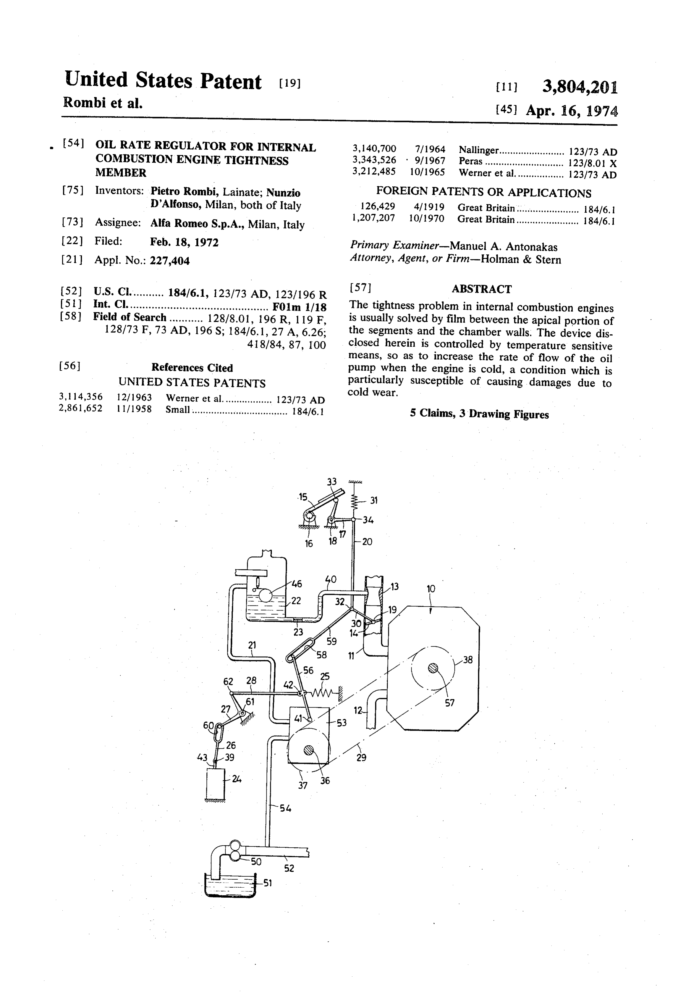
54) OIL RATE REGULATOR FOR INTERNAL 3, 140,700 7/1964 Nallinger........................ 123/73 AD COMBUSTON ENGINE TIGHTNESS 3,343,526 9/1967 Peras............................. 123/8.01 X MEMBER 3,212,485 10/1965 Werner et al.................. 123/73 AD 75) Inventors: Pietro Rombi, Lainate; Nunzio FOREIGN PATENTS OR APPLICATIONS D'Alfonso, Milan, both of Italy 126,429 4/1919 Great Britain....................... 184/6. 1 73) Assignee: Alfa Romeo S.p.A., Milan, Italy 1,207,207 10/1970 Great Britain....................... 184/6. 22 Filed: Feb. 18, 1972 Primary Examiner-Manuel A. Antonakas (21) Appl. No.: 227,404 Attorney, Agent, or Firm-Holman & Stern 52 U.S. Cl........... 184/6.1, 123/73 AD, 123/196 R 57 ABSTRACT 51 int. Cl. ............................................. F01m 1/18 The tightness problem in internal combustion engines 58) Field of Search ........... 128/8.01, 196 R, 1 19 F, is usually solved by film between the apical portion of 128/73 F, 73 AD, 196 S; 184/6. 1, 27 A, 6.26; the segments and the chamber walls. The device dis 41 8/84, 87, 100 closed herein is controlled by temperature sensitive means, so as to increase the rate of flow of the oil 56 References Cited pump when the engine is cold, a condition which is UNITED STATES PATENTS particularly susceptible of causing damages due to cold wear.
3, 14,356 2/1963 Werner et al.................. 123/73 AD 2,861,652 l l / 1958 Small ................................... 184/6.1 5 Claims, 3 Drawing Figures
Page 2
Drawing sheet — no readable text.
Page 3
Drawing sheet — no readable text.
Page 4
OIL RATE REGULATOR FOR INTERNAL self, or from any component part of the engine having COMBUSTON ENGINE TIGHTNESSMEMBER: a temperature that can be used as a temperature refer encing member. The device can be applied to any inter
BACKGROUND OF THE INVENTION nal combustion engine and more particularly, to rotary engines of the NSU-Wankel type. As is well known, en
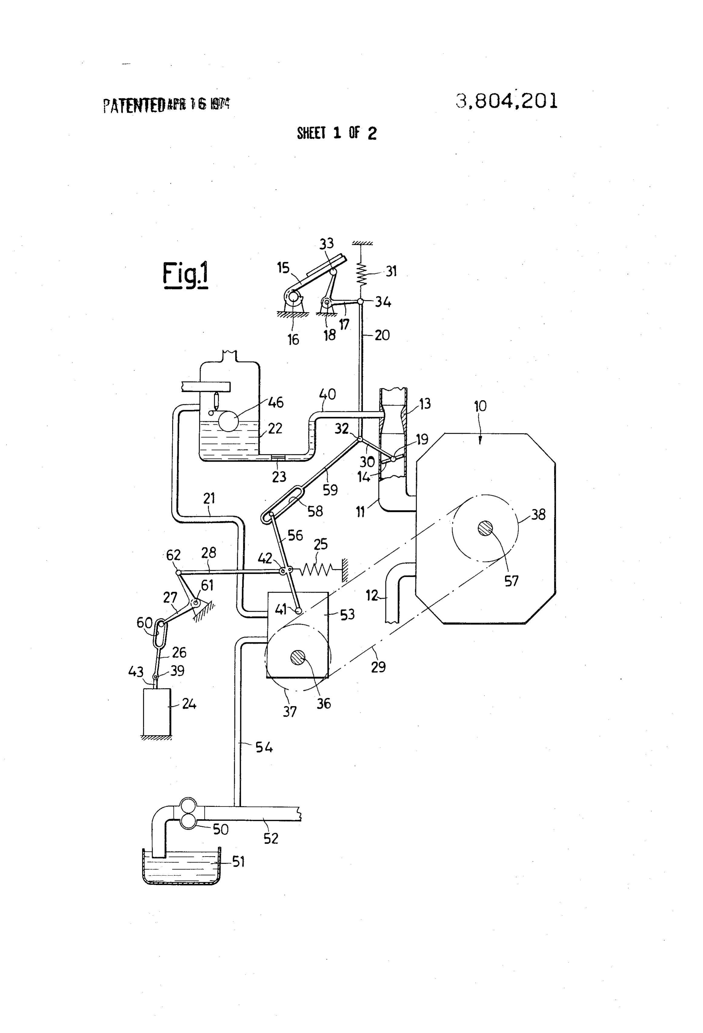
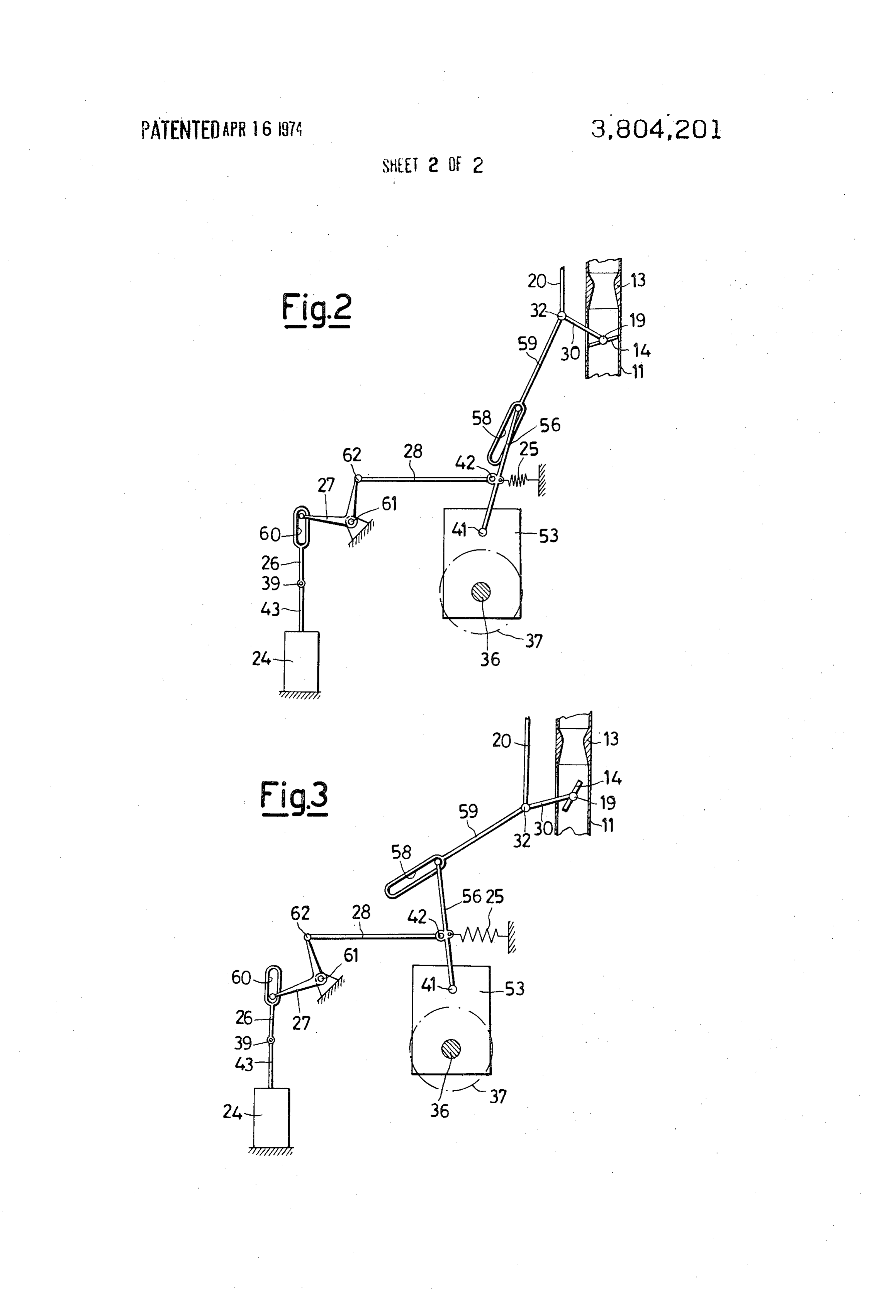
This invention relates to a device-adapted to ensure gines of this kind are generally provided with a lubrica a more efficient lubrication and generally to reduce in tion system in which the rate of flow of lubricating oil this manner the wear of tightness members in engines to the apical tightness segments is regulated by a me and more particularly, it relates to rotary engines of the tering pump which send the lubricant directly into the NSU-Wankel type, in which the wear of the apical O stator or the carburetor float chamber in an amount tightness segments are particularly, serious. The device which is increased as the rate of revolution of the en according to the invention is useful, beyond any doubt, gine is increased and often also as the engine load is in in all the internal combustion engines in which the creased (position of the throttle). tightness of the working chambers is entrusted to seg SUMMARY OF THE INVENTION ments, rings or such members which slide against sur 15 faces. According to the invention, a device for regulating As is known, the wear of sliding tightness members the rate of flow of the lubrication oil to the sliding tight is maintained within acceptable limits by a lubrication ness members of the combustion chamber of an inter of the contacting surfaces and, according to the present nal combustion engine comprises an apparatus for status of the engine-building art, several ways are: feeding oil to said members at a rate of flow which is known, which are more or less efficient, to obtain it. a function at least of one of the parameters formed by It is known to feed the tightness members which slide the rate of revolution of the engine and the engine load, against surfaces with lubricating oil in metered and is further characterized by comprising means sensi amounts as a function of the rate of revolution and the tive to the engine temperature and acting upon said ap engine load. Such a metering action is entrusted, for ex 25 paratus in the sense of causing the rate of flow thereof ample, to oil-retaining piston rings in the reciprocating to be increased as determined by said parameters when engines and to lubricating oil metering devices on the said temperatures lie below a preselected value, rotary engines of the NSU-Wankel type. BRIEF DESCRIPTION OF THE DRAWINGS An oil feed sometered has proven to be inadequate to protect the tightness members, and the surfaces on 30 In order that the objects and the features of the de which, they slide, as from the corrosive compounds as vice according to the invention may become clearer, an formed in a cold engine. It should be considered, more exemplary embodiment will be described hereinafter over, that when the engine is cold, the lubricating oil and illustrated in the accompanying drawings, wherein: encounters a greater difficulty in being evenly spread on the surfaces due to its higher viscosity. It occurs, in 35 FIG. 1 is a diagrammatical view of a regulating device fact, that the most intensive wear is experienced with as applied to an internal combustion engine. cold engines, i.e., from starting and continuing during FIGS. 2 and 3 are close up views of details of FIG. 1 the time which is required by the engine to attain its in the different position as taken in operation. working temperature.
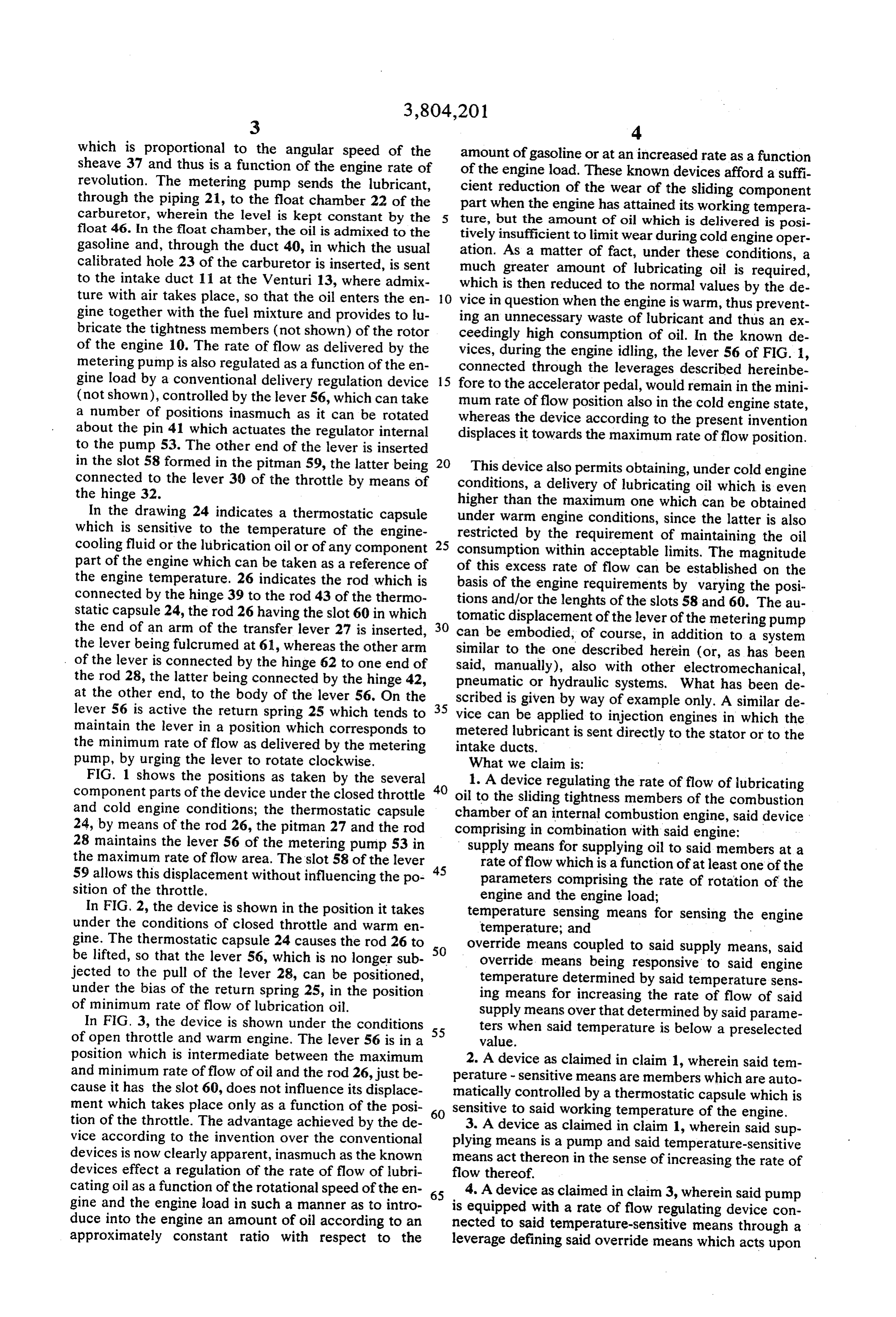
Under these conditions, in order to originate a layer 40 DETAILED DESCRIPTION OF THE PREFERRED of lubricating oil between the surfaces, to a thickness EMBODIMENT which is sufficient to reduce wear or, at least, to con In FIG. 1, the numeral 10 generally indicates a rotary fine it within acceptable limits, it is suggested, accord engine of the NSU-Wankel type of conventional make, ing to the invention, the lubricating oil is supplied to 45 having a mixture intake duct 11 and an exhaust duct the engine tightness members during the cold engine 12. Venturi 13 and butterfly throttle 14 are mounted in operation in an amount which exceeds the one supplied the intake duct.
under the same operative conditions as when the en The accelerator pedal is indicated at 15, and at 16 gine is warm. This object is attained by the lubricating there is the pivot thereof, 17 being the transfer lever oil rate of flow regulating device according to the pres pivoted at 18, which has one end 33 of the lever arm ent invention, which acts upon the lubricating oil me 50 resting against the accelerator pedal and is connected tering device as a function of the engine temperature, at the end of the other arm by the hinge 34 to the rod in the sense of allowing an increase in the rate of flow 20. In this position, there is applied the return spring of the lubricating oil during the time required by the 31, the rod 20 being connected by the hinge 32 to the engine, to attain warm up. lever 30 which is made integral with the butterfly throt The correction of the rate of flow of lubricant as ob 55. tle 14 inserted in the duct 11, the throttle being rotat tained with the device according to this invention per able about its pivot 19.
mits to do away with the defects enumerated above and At 50 there is indicated the oil pump which draws oil concurrently permits to reduce the cold wear of the en from the pump 51 and sends it through the piping 52 gine tightness members. 60 to the component members of the engine which require Said device, which carries out the regulation of the it, as well as to the metering pump 53 via the piping 54. lubricating oil rate of flow as a function of the engine temperature, in the sense of increasing the rate of flow The arbor 36 of the metering pump receives its drive aforesaid, is operated either manually or automatically from the mainshaft 57 through a belt drive as diagram by a member which is sensitive to the engine tempera 65 matically shown at 29, in the drawing; where there have ture. Such a temperature information can be drawn been shown in dotted lines the sheave 37 is keyed to the from the temperature of the engine-cooling fluid, as pump arbor, the sheave 38 being keyed to the arbor 57. well as from the temperature of the lubricating oil it Thus the metering pump delivers a rate of flow of oil
Page 5
which is proportional to the angular speed of the amount of gasoline or at an increased rate as a function sheave 37 and thus is a function of the engine rate of of the engine load. These known devices afford a suffi revolution. The metering pump sends the lubricant, cient reduction of the wear of the sliding component through the piping 21, to the float chamber 22 of the part when the engine has attained its working tempera carburetor, wherein the level is kept constant by the ture, but the amount of oil which is delivered is posi float 46. In the float chamber, the oil is admixed to the tively insufficient to limit wear during cold engine oper gasoline and, through the duct 40, in which the usual ation. As a matter of fact, under these conditions, a calibrated hole 23 of the carburetor is inserted, is sent much greater amount of lubricating oil is required, to the intake duct 11 at the Venturi 13, where admix which is then reduced to the normal values by the de ture with air takes place, so that the oil enters the en O vice in question when the engine is warm, thus prevent gine together with the fuel mixture and provides to lu ing an unnecessary waste of lubricant and thus an ex bricate the tightness members (not shown) of the rotor ceedingly high consumption of oil. In the known de of the engine 10. The rate of flow as delivered by the vices, during the engine idling, the lever 56 of FIG. 1, metering pump is also regulated as a function of the en connected through the leverages described hereinbe gine load by a conventional delivery regulation device 15 fore to the accelerator pedal, would remain in the mini (not shown), controlled by the lever 56, which can take mum rate of flow position also in the cold engine state, a number of positions inasmuch as it can be rotated whereas the device according to the present invention about the pin 41 which actuates the regulator internal displaces it towards the maximum rate of flow position. to the pump 53. The other end of the lever is inserted in the slot 58 formed in the pitman 59, the latter being This device also permits obtaining, under cold engine connected to the lever 30 of the throttle by means of conditions, a delivery of lubricating oil which is even the hinge 32. higher than the maximum one which can be obtained In the drawing 24 indicates a thermostatic capsule under warm engine conditions, since the latter is also which is sensitive to the temperature of the engine restricted by the requirement of maintaining the oil cooling fluid or the lubrication oil or of any component 25 consumption within acceptable limits. The magnitude part of the engine which can be taken as a reference of of this excess rate of flow can be established on the the engine temperature. 26 indicates the rod which is basis of the engine requirements by varying the posi connected by the hinge 39 to the rod 43 of the thermo tions and/or the lenghts of the slots 58 and 60. The au static capsule 24, the rod 26 having the slot 60 in which tomatic displacement of the lever of the metering pump the end of an arm of the transfer lever 27 is inserted, 30 can be embodied, of course, in addition to a system the lever being fulcrumed at 61, whereas the other arm similar to the one described herein (or, as has been of the lever is connected by the hinge 62 to one end of said, manually), also with other electromechanical, the rod 28, the latter being connected by the hinge 42, pneumatic or hydraulic systems. What has been de at the other end, to the body of the lever 56. On the scribed is given by way of example only. A similar de lever 56 is active the return spring 25 which tends to 35 vice can be applied to injection engines in which the maintain the lever in a position which corresponds to metered lubricant is sent directly to the stator or to the the minimum rate of flow as delivered by the metering intake ducts.
pump, by urging the lever to rotate clockwise. What we claim is:
FIG. 1 shows the positions as taken by the several 1. A device regulating the rate of flow of lubricating component parts of the device under the closed throttle 40 oil to the sliding tightness members of the combustion and cold engine conditions; the thermostatic capsule chamber of an internal combustion engine, said device 24, by means of the rod 26, the pitman 27 and the rod comprising in combination with said engine: 28 maintains the lever 56 of the metering pump 53 in supply means for supplying oil to said members at a the maximum rate of flow area. The slot 58 of the lever rate of flow which is a function of at least one of the 59 allows this displacement without influencing the po 45 parameters comprising the rate of rotation of the sition of the throttle. engine and the engine load; In FIG, 2, the device is shown in the position it takes temperature sensing means for sensing the engine under the conditions of closed throttle and warm en temperature; and gine. The thermostatic capsule 24 causes the rod 26 to 50 override means coupled to said supply means, said be lifted, so that the lever 56, which is no longer sub override means being responsive to said engine jected to the pull of the lever 28, can be positioned, temperature determined by said temperature sens under the bias of the return spring 25, in the position ing means for increasing the rate of flow of said of minimum rate of flow of lubrication oil. supply means over that determined by said parame In FIG. 3, the device is shown under the conditions ters when said temperature is below a preselected of open throttle and warm engine. The lever 56 is in a 55 value.
position which is intermediate between the maximum 2. A device as claimed in claim 1, wherein said tem and minimum rate of flow of oil and the rod 26, just be perature - sensitive means are members which are auto cause it has the slot 60, does not influence its displace matically controlled by a thermostatic capsule which is ment which takes place only as a function of the posi sensitive to said working temperature of the engine. tion of the throttle. The advantage achieved by the de 60 3. A device as claimed in claim 1, wherein said sup vice according to the invention over the conventional plying means is a pump and said temperature-sensitive devices is now clearly apparent, inasmuch as the known means act thereon in the sense of increasing the rate of devices effect a regulation of the rate of flow of lubri flow thereof.
cating oil as a function of the rotational speed of the en 4. A device as claimed in claim 3, wherein said pump gine and the engine load in such a manner as to intro 65 is equipped with a rate of flow regulating device con duce into the engine an amount of oil according to an nected to said temperature-sensitive means through a approximately constant ratio with respect to the leverage defining said override means which acts upon
Page 6
a control in said device in the sense of increasing the livered by said pump.
rate of flow delivered by said pump when said tempera 5. A device as claimed in claim 1, wherein said sup ture is below a pre-selected value, said leverage leaving said control free to be actuated as a function of said pa plying means introduces oil into the engine intake duct. rameters in the sense of varying the rate of flow as de- 5 ck k k be k

Page 7
UNITED STATES PATENT OFFICE
CERTIFICATE OF CORRECTION
Patent No. 38.0420 Dated April 16, 1974 Inventor(s) Pietro Rombi and Nunzio D'Alfonso It is certified that error appears in the above-identified patent and that said Letters Patent are hereby corrected as shown below:
(30) Foreign Application Priority Data
Signed and sealed this l7th day of September 1974.
(SEAL)
Attest:
McCOY M. GIBSON JR. C. MARSHALL, DANN Attesting Officer Commissioner of Patents
F ORM PO-1050 (O-69) uscom Mao c 6037 6.d69 A U.S. GOVERNMENT PRNNG office : 1969 d -366-334.
Provenance
- Collection
- Cited prior art
- Original PDF
- patentimages.storage.googleapis.com →
- Filed
- 1972-02-18
- Pages
- 7
- Method
- pdftotext (the PDF's own text layer) + pdftoppm 300dpi page scans
- Source
- Google Patents bibliographic record
- Granted
- 1974-04-16
- Inventors
- P Rombi; Alfonso N D; Alfa Romeo SpA
- Transcribed from
- patentimages.storage.googleapis.com →