patent · US2294748
Ribbon flame burner
1 September 1942
Page 1
Drawing sheet — no readable text.
Page 2
Drawing sheet — no readable text.
Page 3
Patented Sept. 1, 1942 2,294,748
UNITED STATES PATENT OFFICE 2,294,748
RIBBoN FLAME BURNER.
Hartwig Millard Hanson, Baltimore, Md, assign or to The C. M. Kemp Manufacturing Com pany, Baltimore, Md., a corporation of Mary and
Application July 24, 1940, serial No. 347,122
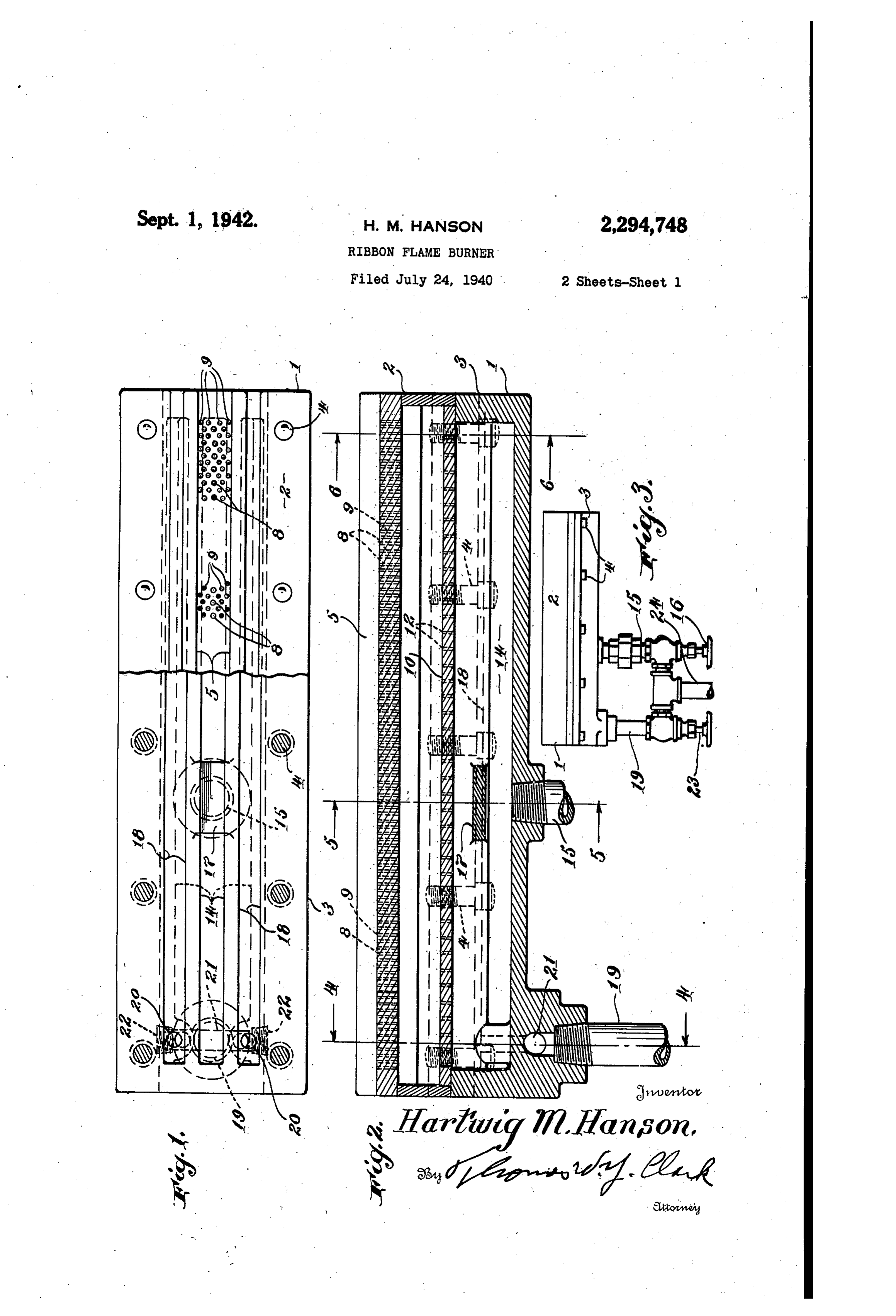
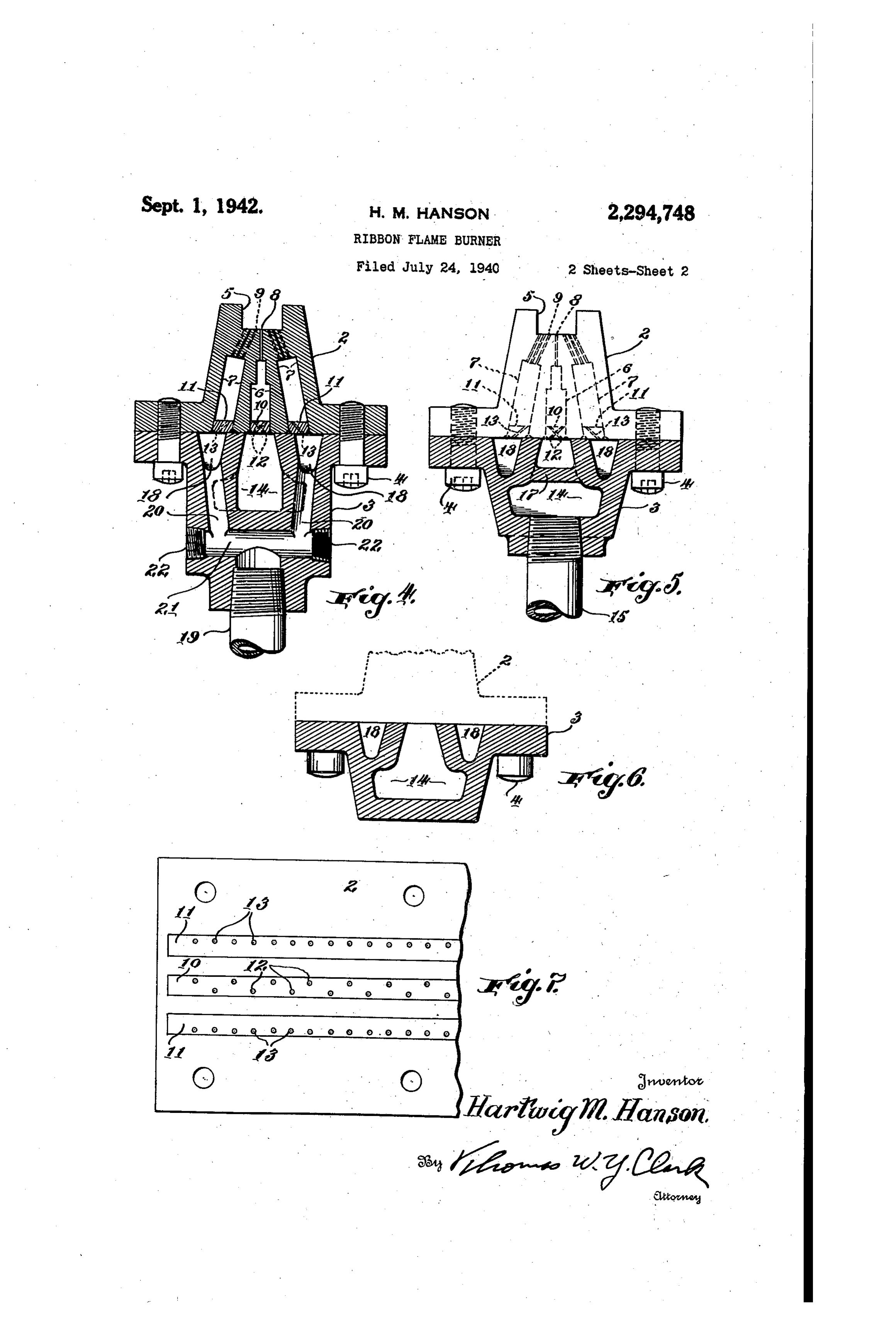
This invention is directed to a burner pecu Figure 6 is a similar view on line 6-6 of Fig liarly adapted to presenting a stiff knife edge, lure 2.
blade like or ribbon like flame, the flame having Figure 7 is a partial inverted plan view of the a high temperature and burning with consid top casting of the burner.
erable pressure to the gas. In the production 5 Similar numerals refer to similar parts in the of such a flame in other burners than this con several views.
struction, the velocity of the gas exceeds the The burner consists of an elongate body made rate of flame propagation with the result that the up of two castings, a top casting 2 and a bottom flame gets so far from the gas source that it casting 3.
is blown out by the force of the gas itself and 10 These two castings are permanently attached it is a purpose of the present burner to produce together by bolts 4. The top casting 2 has a such a ribbon like blast fame of high tempera trough 5 in its top section and in its bottom sec ture that will not go Out. tion a central longitudinally extending slot. 6 . The burner is peculiarly useful in the Soldering and lateral longitudinal extending slots T. Cen of tin cans, which are taken through a solder tral slot 6 has spaced Orifices 8 leading therefrom bath for soldering the side seams. The seams to the center of the trough 5. Lateral slots have of such cans must be heated to a very high tem sloped passages 9 forming orifices at their top perature so as not to extract heat from the Soldier opening on each side of the orifices 8 in the bot bath and thereby cool it and yet this flame must tom of the trough 5.
be so narrow and restricted in its width as not 20 In the preferred construction the orifices 9 are to heat appreciably the can body away from the arranged in staggered longitudinally extending Sea, rOWS as ShoWn in Fig. 1, forming pilot flame ori In the production of Such can bodies, On mod fices.
ern machines, they come through at such a rapid After cutting the slots 6 and 7 in the top cast rate that the burners heretofore constructed have ing 2, the lower portions of these slots are closed, either heated too much of the can bodies or they the Central one by plate O and the lateral ones have not been able to heat them sufficiently to by plates ff. Plate O is drilled so that it has keep from extracting heat from the solder bath, alternately sloped spaced passages 2 and plates through which they go. are drilled to have sloped passages 3. These Of course other uses of the burner in which a 30 sloped passages equalize the pressure of the fuel knife edge flame of very high temperature is and cause the fuel in its flow to impinge upon required are met with frequently in the industry the walls of the slots 6 and 7 to further equalize and this example is only given by way of illus the pressure so that a fuel is presented to the tration of the utility of the invention. burning orifices having a uniform pressure dis The burner of the invention is an improve 3. 5 tribution. .
-ment over the burner of the Patent No. 1204,359 The lower casting 3 has a centrally disposed dated November 7, 1916, which has been tried and chamber 4, when the castings are joined to found not to produce sufficient heat in the time gether, admitting fuel to the passages 2 and allowed by certain rapid manufacturing proc central slot 6. Fuel is fed to this chamber f4 eSSeS. 40 through pipe 5 and it is controlled through Other objects and advantages of the invention will be apparent from the following description valve 6. A baffle f7 is placed in the chamber immediately above the entrance to the pipe 5 and accompanying drawings, which form a part to divert the flow of fluid to each end of the hereof, and in which: chamber and to prevent undue pressure imme Figure 1 is a top plan view of a burner embody diately above the pipe. Lateral chambers f8 are ing the present invention, with part of the top also in this lower casting and these, when the casting removed. castings are connected, connect directly with Figure 2 is a vertical sectional view of the lateral slots 7 in upper casting 2 through pas burner. Sages 3. These passages 8 are fed by a pipe Figure 3 is a side elevational view showing the 9 through side openings 20 drilled into the cast multiple control valves. ing. As the casting is formed the fuel passes Figure 4 is a cross-sectional view on line 4-4 through opening 2 connecting the opening from of Figure 2. pipe 9 with the openings 20 and the outer ex Figure 5 is a CrOSS-Sectional view on line 5-5 tremities of this opening 2 are closed by plugs of Figure 2. 55 22, The flow of fuel through pipe 9 is con
Page 4
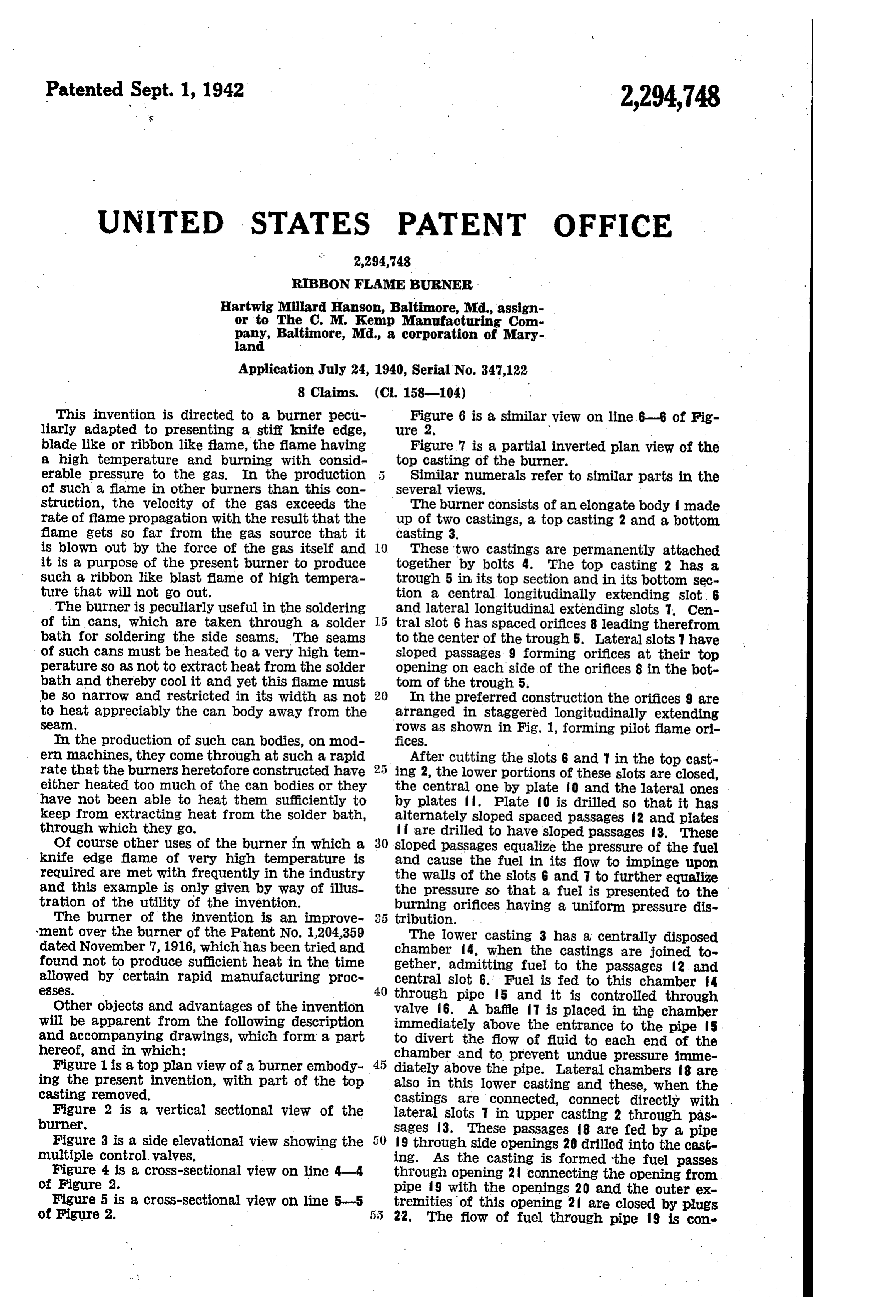
trolled by valve 23 and fuel passes through cen Section and means to Substantially equalize the fuel pressure through the length of said cham tral pipe 24 to both valves 6 and 23. ber, said shell also having a separate lateral By this construction a ribbon like blast flame chamber with pilot flame orifices passing there may be projected from the central orifices 8 un der great pressure and it may extend some dis from through said orifice section to produce a tance from the trough 5 and the tendency of the pilot flame fame extending lengthwise of Said blast and separately controlled means to admit flame to go out or be blown off because of the fuel through said fuel feeding section directly to pressure of the fuel is prevented by the Support ing lateral pilot flames burning with less pressure said lateral chamber.
4. A ribbon flame burner comprising elongated from Orifices 9, these side flames being Sloped to O integral ward the center flame to give it greater support Orifice and fuel feeding sections and in burning. The structure permits a center flame means to laterally connect said sections together of continuous sheet or ribbon like formation sub to form a closed shell having therein a central stantially without perceptible division into sepa chamber with longitudinally extending blast rate jets and without high and low points or val s flame Orifices leading therefrom through said leys and ridges, and as much flame and there orifice Section to produce a substantially longi fore heat as is possible is concentrated in a sharp tudinally means to continuous line blast flame, controlled admit fuel to said chamber through knife-like line where it burns constantly, The concentration of heat is so great that one foot of said fuel feeding section and means to substan this burner will supply as much heat as four Or 20 tially equalize the fuel pressure through the length of said chamber, said shell also having five feet of other available burners. lateral chambers on each side of and closed off The Separate control of the two flames allows from said central chamber with pilot flame ori for their accurate adjustment in relation to each fices passing therefrom through said orifice sec other, and the main cut-off can be manipulated without disturbing that control when the burner tion on each side of said blast flame orifices, to is shut down after use. produce pilot flames extending lengthwise of said It will be apparent that modifications may be blast flame and means to admit fuel through said made in the apparatus to carry out the invention fuel feeding section directly to said lateral cham without departing from the principles thereof. bers.
What is claimed as new and desired to be se 30 5. A ribbon flame burner comprising elongated cured by Letters Patent is: integral orifice and fuel feeding sections and means to laterally connect said sections together 1. A ribbon flame burner comprising elongated to form a closed shell having therein a chamber integral Orifice and fuel feeding sections and with longitudinally extending blast fame orifices means to laterally connect said sections together to form a closed body having therein a centrally produce therefrom 35 leading through said orifice section to a substantially longitudinally continu extending chamber and a central row of closely ous line blast flame, controlled means to admit Spaced Orifices leading therefrom through said fuel to said chamber through said fuel feeding Orifice Section to the top thereof, and said body having therein interconnected lateral chambers siO Section, said shell also having a separate lateral chamber with pilot flame orifices passing there extending one on each side of said central cham ber and rows of closely spaced orifices in said ori from through Said orifice section, the passages of fice section on each side of and adjacent to said Said orifices being sloped inwardly toward the blast flame to produce a pilot flame extending central row leading to the adjacent lateral cham lengthwise of and intercepting and joining said bers said fuel feeding section having therein a blast fame at a distance from said burner, and fuel inlet for said lateral interconnected cham 45 Separately controlled means to admit fuel bers and a separate fuel inlet for said central through said fuel feeding section directly to said chamber.
2. A ribbon flame burner comprising elongated lateral chamber.
6. A ribbon flame burner comprising elongated integral Orifice and fuel feeding sections and integral means to laterally connect said Sections together 50 means to orifice and fuel feeding sections and to form a closed body said orifice section having to form a laterally connect said sections together closed shell having therein a chamber in the top thereof an upwardly directed longitu dinally extending trough, and said body having with longitudinally extending blast flame orifices therein a centrally extending chamber and a leading therefrom through said orifice section to produce a Substantially longitudinally continuous central row of closely spaced orifices leading therefrom through said orifice section to the cen line blast flame, controlled means to admit fuel ter of the said trough bottom and said body also ing directly to said chamber through said fuel feed having therein interconnected lateral chambers stantially Section, and means in said chamber to sub extending one on each side of said central cham equalize the fuel pressure through the ber and rows of closely spaced orifices in said 60 length of said chamber, said shell also having a Orifice Section on each side of and adjacent to Separate lateral chamber with pilot flame orifices Said central row in said trough leading to the ad passing therefrom through said orifice section, jacent lateral chamber said fuel feeding section the passages of said orifices being sloped inwardly having therein a fuel inlet for said lateral inter toward the blast flame to produce a pilot flame connected chambers and a separate fuel inlet for 65 extending joining the lengthwise of and intercepting and blast flame at a distance from said said central chamber.
3. A ribbon flame burner comprising elongated burner, and separately controlled means to ad mit fuel through said fuel feeding section directly integral Orifice and fuel feeding sections and means to laterally connect said sections together to said lateral chamber.
7. A ribbon flame burner comprising elongated to form a closed shell having therein a chamber 70 integral with longitudinally extending blast flame orifices orifice and fuel feeding sections and leading therefrom through said orifice section to means to laterally connect said sections together produce a Substantially longitudinally continu to form a closed shell having therein a central ous line blast flame, controlled means to admit chamber with longitudinally extending blast fuel to said chamber through said fuel feeding 75 flame orifices leading therefrom through said ori
Page 5
fice section to produce a substantially longitudi flame orifices leading therefrom through said ori nally continuous line blast flame, controlled fice section to produce a substantially longitudi means to admit fuel to said chamber through nally continuous line blast flame, controlled Said fuel feeding Section, Said shell also having means to admit fuel to said chamber through lateral chambers on each side of and closed off s said fuel feeding section, and means to substan from said central chamber with pilot flame ori tially equalize the fuel pressure through the fices passing therefrom through said orifice sec length of Said chamber, Said chamber also having tion, on each side of Said blast flame Orifices, the lateral chambers on each side of and closed off passages of Said orifices being sloped inwardly from said central chamber with pilot flame ori toward the blast flame to produce pilot flames 10 fices passing therefrom through said Orifice Sec extending lengthwise of and intercepting and tion, On each side of Said blast flame orifices, the joining Said blast flame at a distance from Said passages of said orifices being sloped inwardly burner, and separately controlled means to admit toward the blast flame to produce pilot fiames fuel through said fuel feeding Section directly extending lengthwise of and intercepting and to said lateral chambers. 5 joining the blast flame at a distance from said 8. A ribbon flame burner comprising elongated burner, and separately controlled means to admit integral orifice and fuel feeding sections and fuel through said fuel feeding section directly means to laterally connect said sections together to said lateral chambers.
to form a closed shell having therein a central chamber with longitudinally extending blast 20 HARTWIG MITARD HANSON.
Provenance
- Collection
- Cited prior art
- Original PDF
- patentimages.storage.googleapis.com →
- Filed
- 1940-07-24
- Pages
- 5
- Method
- pdftotext (the PDF's own text layer) + pdftoppm 300dpi page scans
- Source
- Google Patents bibliographic record
- Granted
- 1942-09-01
- Inventors
- Hanson Hartwig Millard; CM Kemp Manufacturing Co
- Transcribed from
- patentimages.storage.googleapis.com →