patent · US3067131
Periodic introduction of granular contact material into high pressure vessel
4 December 1962
Page 1 — bibliographic record
Dec. 4, 1962 E. V. BERGSTROM 3,067,131
PERIODIC INTRODUCTION OF GRANULAR CONTACT MATERIAL
INTO HIGH PRESSURE WESSE,
Filed March 27, 1961 3 Sheets-Sheet
SEAL GAS OUT
LEVE
INDICATOR,
GAs iN -- 37- - Egy ELEVATORS
FEED
PREPARATION AR
COOLANT
PRODUCT
SEAL 8 PURGE GAS
INVENTOR
Eric V. Bergstrom
ATTORNEY
Page 2
Dec. 4, 1962 E. V. BERGSTROM 3,067,131
PERIODIC INTRODUCTION OF GRANULAR CONTACT MATERIAL
INTO HIGH PRESSURE WESSEL
Filed March 27, 196l 3. Sheets-Sheet 2
CYCLE a TMER A
INVENTOR
Eric V. Bergstron
Page 3
Drawing sheet — no readable text.
Page 4
United States Patent Office 3,067,131 Patented Dec. 4, 1962
vated pressure such as 15-100 p.s. i. (gauge) since cer 3,067, 31 tain process advantages are obtained by the use of these PERIODC NTROSU CEON OF GERANJEAR elevated pressures. The reactants are preheated to about CONTACT MATERSAL ENTO HESG EPRES 700-800° F. and introduced into the conversion zone as SURE WESSEL a vapor, liquid or mixture of both. The hydrocarbons Eric W. Bergstro, Byrana, Coian, assiga or to Socory pass through the voids in the bed and are withdrawn as Mobil Oil Company, Eirc., a corporation of New York converted products after passage through the proper Fied Mar. 27, 1961, Ser. No. 93,540 depth of catalyst bed. The catalyst cools and becomes 1. Ciain. (C. 268-573) spent during use and hence must be removed from the This invention relates to the feeding of solid granular O conversion zone and replaced with fresh catalyst from particles from a low pressure region to a region of Sub time to time. The catalyst removed from the bottom ar stantially higher pressure. It more particularly relates of the conversion zone is transferred to the top of a to the downward introduction of granular catalyst or gravitating bed of the solid material in the regeneration granular contact material into a gas contacting Zone main ZOE.
tained at advanced pressure, such as a reaction Zone, 5 in Athegas,regeneration usually air, is introduced into the bed of solids zone to burn carbonaceous material from a storage zone maintained at a lower pressure lo cated above the contacting Zone. In less restricted form, from the surface of the catalyst or contact material. The however, the invention relates to the transfer of granular flue gas formed is removed continuously from the zone material downwardly to an enclosed region and inter after passage through the required depth of catalyst bed. mittent transfer from said region to a zone maintained The pressure is generally maintained at substantially at mospheric pressure, although in some instances, it may under high gaseous pressure.
The invention is particularly suited for use in moving be desirable to operate this zone at other pressures. The temperature in the regenerating zone is usually main bed systems of the general type in which reaction and tained at about 1000-1300 F. When inerts are used regeneration are accompiished simultaneously in sepa rate confined zones through which the catalyst or contact 25 as a heat transfer medium, such as mullite, carborun dum, coke, or fused alumina, the temperature may be material is passed as a relatively compact bed of solid particles. The fluid reactants are passed through the substantially in excess of 1300 F., but for catalytic bed of solid particles in the reaction zone continuously cracking, this upper limit must not be exceeded or the and the regenerating fluid is passed through the bed of 30 unfitcatalyst material will be heat damaged and rendered solids in the regeneration zone. The particles are trans for re-use. The heat-damaging tempearture varies ferred continuously from the bottom of one zone to the to some extent with the type of catalytic material being top of the alternate Zone to complete an enclosed cyclic used. For example, the limit for natural or treated clay path. The particles may be elevated between the zones catalyst is about 1200. F., whereas the limit for syn by means of mechanical elevators of the continuous thetic silica gel type catalyst is about 1400 F. It is bucket or Redler type, fluid lifts wherein the particles essential in these processes that the catalyst not be dam are propelled upwardly through a lift passage in a stream aged either chemically or physically since the catalyst of rapidly-moving lift gas or gas pressure lifts wherein is so expensive that it must be used repeatedly for long the granular material is moved upwardly through an up periods of time in order to make these processes eco Wardly-extending pipe as a continuous confined column nomically feasible.
by means of the gas pressure differential across the pipe. 40 tomTheof regenerated catalyst is withdrawn from the bot the regenerating zone and transferred to the top
The granular material used in this invention must be large enough to flow by gravity as compacted columns of the reaction or conversion zone. The problem of through drain legs of restricted cross-section. For ex introducing the granular catalyst into the conversion zone ample, the particles may be in the size range of about against the advanced pressure maintained in that zone 3-60 mesh Tyler but must not be of a size smaller than has troubled industry since the origin of these continuous 100 mesh Tyler commonly referred to as powder. The conversion systems. Star valves and gas type mechanical measuring devices as well as positive feeding valves, screw size range preferred is of the order of 4-12 mesh Tyler conveyors, catalyst pumps, pressure lock systems with or, in other words, particles of about 78' to 4' in di gas-tight valves in catalyst lines before and after pres ameter. Various processes to which this invention can be applied include reforming, hydroforming, cracking, 50 Suring chambers, have all been suggested heretofore in the prior art as means for feeding catalyst from a low isomerization, alkylation, isoforming, aromatization, de pressure hydrogenation, hydrogenation, cyclizing, dehydrocycliz Zone to a higher pressure zone therebelow. ing, treating, polymerization, the conversion of propane These valves and devices all cause high catalyst attri to acetyylene, coking and vis-breaking. Various materi 55 tion losses and are themselves subjected to severe wear and rapid failure at the high temperature conditions in als, Such as natural or treated clays, synthetic associa tions of alumina, chromia and magnesia or metal, porce involved. The problem of maintaining proper lubrication the moving parts of such mechanical feed means is lain or glass fragments can be used as the contact ma terial. a serious one and the failure of proper lubrication re The invention has broad application to many processes, 60 Sults in the failure of the mechanical feed device. Such mechanical feed devices at best require constant atten such as those listed above, as well as to other gas-solid tion from the contacting operations, in which a granular material must eventually to failoperator and have always been found with resultant disruption in the opera be introduced periodically into a high pressure reaction tion of the conversion system.
Zone or contacting zone without damage to the granular material. For convenience, the invention will be de 65 Another means suggested by the prior art for feeding scribed with reference to the high-pressure catalytic crack catalyst into pressure reacting zones is the gravity feed ing of hydrocarbons to produce lighter material boiling leg described and claimed in U.S. Patents Nos. 2,410,309 in the gasoline boiling range. In this process, the cata and 2,531,365. This comprises an elongated substan lyst, such as 4-10 mesh Tyler gel beads, may be gravi tially compact column of catalyst in an upwardly-extended tated as a substantially compact bed through a reaction 70 passage above the reaction zone in open communication Zone. This conversion or reaction zone is maintained with the pressured reaction zone. The calculated head or at a temperature of about 800-1000 F. and at an ele Weight of catalyst in the column per unit of cross-sectional
Page 5
area is sufficient to permit the catalyst to feed into the pactness of the bed substantially before it reaches the sur reaction or conversion zone smoothly and continuously face of the bed. In a preferred embodiment of the inven against the advanced pressure without restrictions in the tion, granular material is gravitated as a compact column passage. There is no head developed in a catalyst column from a supply zone through a first passage to a pressuring maintained in compacted form in the manner that a fluid zone when the pressure in that zone is low and down head is developed at the base of a pipefull of fluid. How wardly from the pressuring zone through a second passage ever, it has been found that when the value obtained by to a high pressure or conversion zone when the pressure dividing the weight of catalyst in the column by the cross in the pressuring zone is elevated to a pressure at least section of the base of the column is above a critical limit, near that of the conversion zone. Direct current is alter the solids will flow downwardly in compact columnar form O nately passed through a solenoid about the first passage into the advanced pressure zone and when the value is when the pressure in the pressuring zone is high and below the critical level, the solids will not flow. It is con through a solenoid about the second passage when the venient, therefore, to refer to the so-called calculated head pressure in the pressuring zone is low to prevent the of catalyst in the feed leg. The column is made as small Seal columns from being blown out of the passages. as possible in cross-section, consistent with the catalyst 15 Other species of the invention are disclosed in detail flow requirements of the reaction zone to prevent the hereinafter.
escape of reactants from the reaction zone. The top of The object of the invention is to provide an improved the column is continuously replenished with catalyst from method and apparatus for transferring a granular contact a storage Zone. These feed legs are a very substantial im material downwardly from a first zone at low pressure provement over the mechanical feeding devices, as is evi 20 into a second zone located therebelow and maintained at denced by their exclusive use in commercial moving bed Substantially high pressure, the distance between the first catalyst systems. However, gravity feed legs of the com and Second zones being substantially less than that which pact flowing catalyst type require the provision of roughly would correspond to a column of contact material or 4-5 feet of leg height per pound of pressure differential catalyst providing a calculated head equal to the pressure across the leg; they cannot be used where the pressure 25 differential between the two zones.
drop per foot of leg exceeds about .20-25 p.s.i./ft. As A further object of the invention is to provide a a result of obvious practical considerations, such legs in ethod and apparatus for feeding periodically a granu have not been recommended in systems requiring feeding lar contact material into a high pressure reaction or con against gaseous pressure differentials in excess of about version zone without requiring an exceedingly tall feed 30 p.S.i. and have not been used commercially for feed ing structure above the reaction zone. ing against pressures in excess of about 15 p.s. i. (gauge). A further object of the invention is to provide an Even in the present day commercial catalytic cracking improved method and apparatus for feeding a granular units, these legs are about 80-100 feet tail and require contact material into a high pressure reaction or con extensive structural steel to support them and surge hop version Zone without damaging the granular contact pers above them at heights up to twice the height which 35 material.
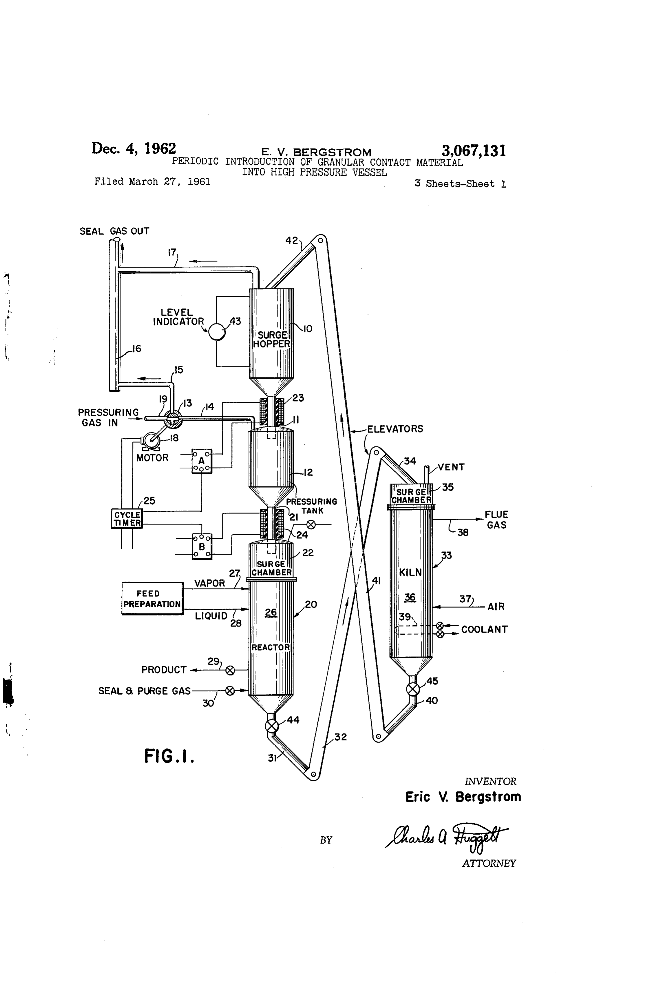
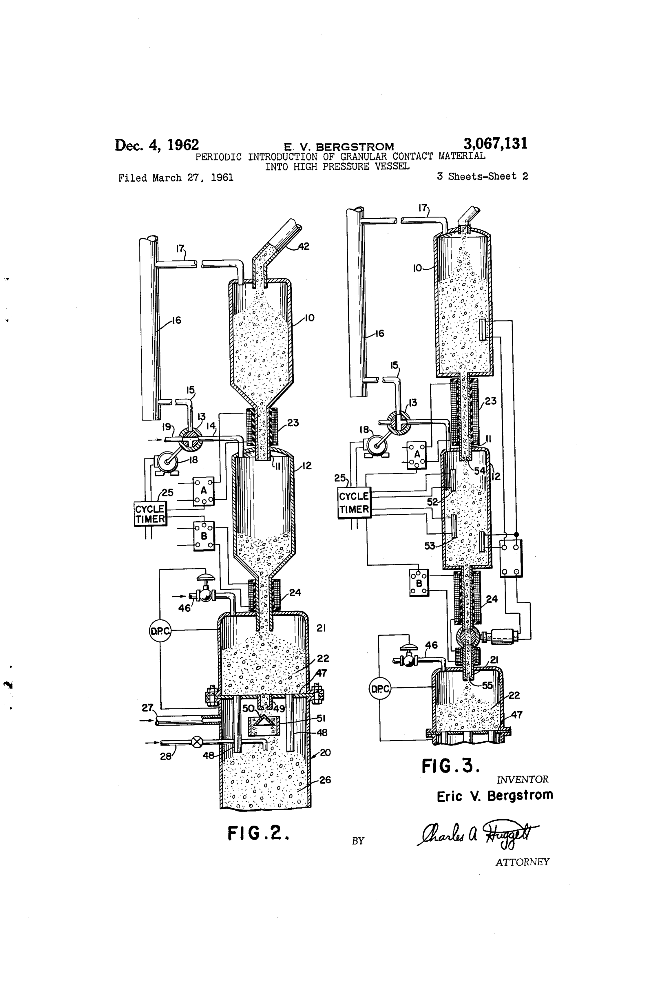
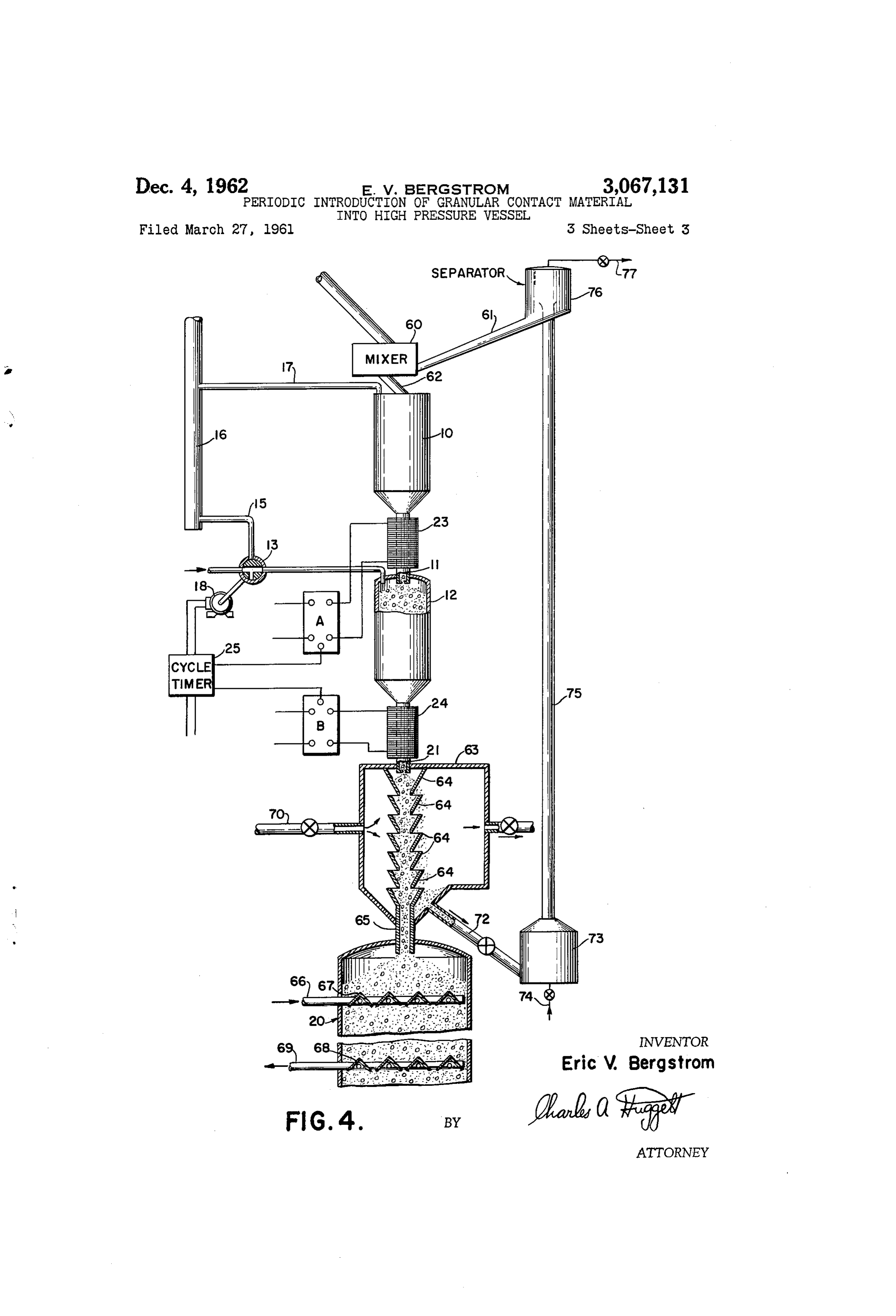
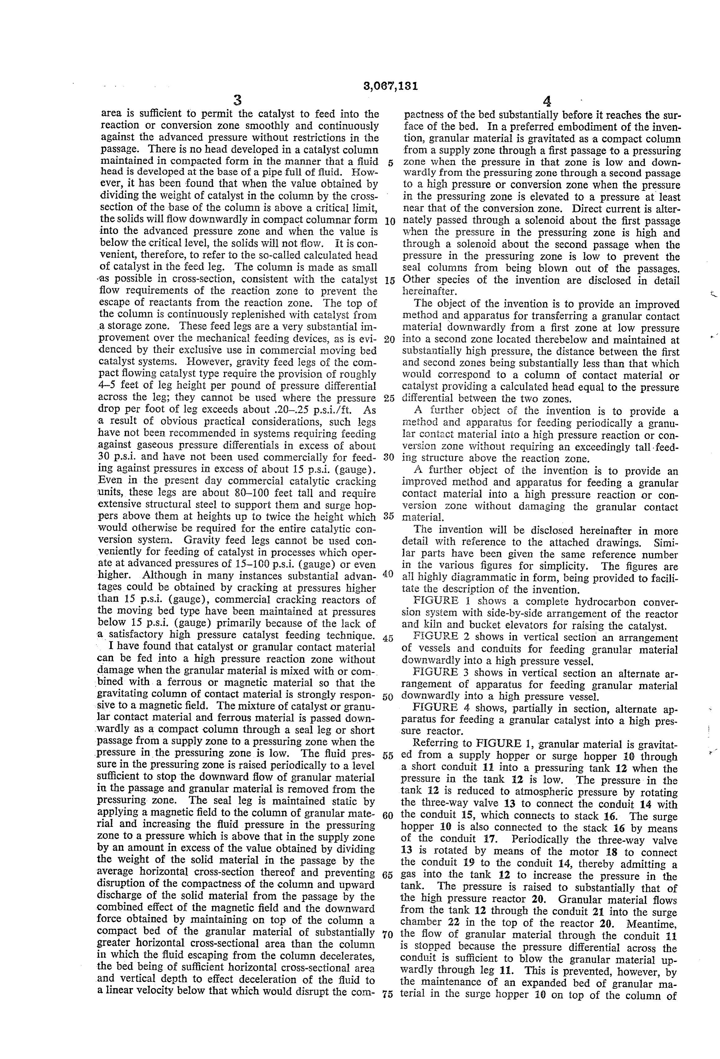
would otherwise be required for the entire catalytic con The invention will be disclosed hereinafter in more version system. Gravity feed legs cannot be used con detail with reference to the attached drawings. Simi veniently for feeding of catalyst in processes which oper lar parts have been given the same reference number ate at advanced pressures of 15-100 p.s. i. (gauge) or even in the various figures for simplicity. The figures are higher. Although in many instances substantial advan 40 all highly diagrammatic in form, being provided to facili tages could be obtained by cracking at pressures higher tate the description of the invention. than 15 p.s. i. (gauge), commercial cracking reactors of FIGURE i shows a complete hydrocarbon conver the moving bed type have been maintained at pressures sion system with side-by-side arrangement of the reactor below 15 p.s. i. (gauge) primarily because of the lack of and kiln and bucket elevators for raising the catalyst. a satisfactory high pressure catalyst feeding technique. FiGURE 2 shows in vertical section an arrangement I have found that catalyst or granular contact material of vessels and conduits for feeding granular material can be fed into a high pressure reaction zone without downwardly into a high pressure vessel. damage when the granular material is mixed with or com FIGURE 3 shows in vertical section an alternate ar bined with a ferrous or magnetic material so that the rangement of apparatus for feeding granular material gravitating column of contact material is strongly respon 50 downwardly into a high pressure vessel. sive to a magnetic field. The mixture of catalyst or granu FIGURE 4 shows, partially in section, alternate ap lar contact material and ferrous material is passed down paratus for feeding a granular catalyst into a high pres Wardly as a compact column through a seal leg or short Sre reactor.
passage from a supply zone to a pressuring zone when the Referring to FIGURE 1, granular material is gravitat pressure in the pressuring zone is low. The fluid pres 55 ed from a supply hopper or surge hopper 10 through sure in the pressuring zone is raised periodically to a level a short conduit 11 into a pressuring tank 12 when the sufficient to stop the downward flow of granular material pressure in the tank 2 is low. The pressure in the in the passage and granular material is removed from the tank 12 is reduced to atmospheric pressure by rotating pressuring zone. The seal leg is maintained static by the three-way valve 13 to connect the conduit 14 with applying a magnetic field to the column of granular mate 60 the conduit 15, which connects to stack 16. The surge rial and increasing the fluid pressure in the pressuring hopper 10 is also connected to the stack 16 by means Zone to a pressure which is above that in the supply zone of the conduit 17. Periodically the three-way valve by an amount in excess of the value obtained by dividing 13 is rotated by means of the motor 18 to connect the weight of the solid material in the passage by the the conduit 9 to the conduit 14, thereby admitting a average horizontal cross-section thereof and preventing 65 gas into the tank 12 to increase the pressure in the disruption of the compactness of the column and upward tank. The pressure is raised to substantially that of discharge of the solid material from the passage by the the high pressure reactor 20. Granular material flows combined effect of the magnetic field and the downward from the tank 12 through the conduit 21 into the surge force obtained by maintaining on top of the column a chamber 22 in the top of the reactor 20. Meantime, compact bed of the granular material of substantially 70 the flow of granular material through the conduit 11 greater horizontal cross-sectional area than the column is stopped because the pressure differential across the in which the fluid escaping from the column decelerates, conduit is sufficient to blow the granular material up the bed being of sufficient horizontal cross-sectional area wardly through leg 11. This is prevented, however, by and vertical depth to effect deceleration of the fluid to the maintenance of an expanded bed of granular ma a linear velocity below that which would disrupt the con terial in the Surge hopper 10 on top of the column of
Page 6
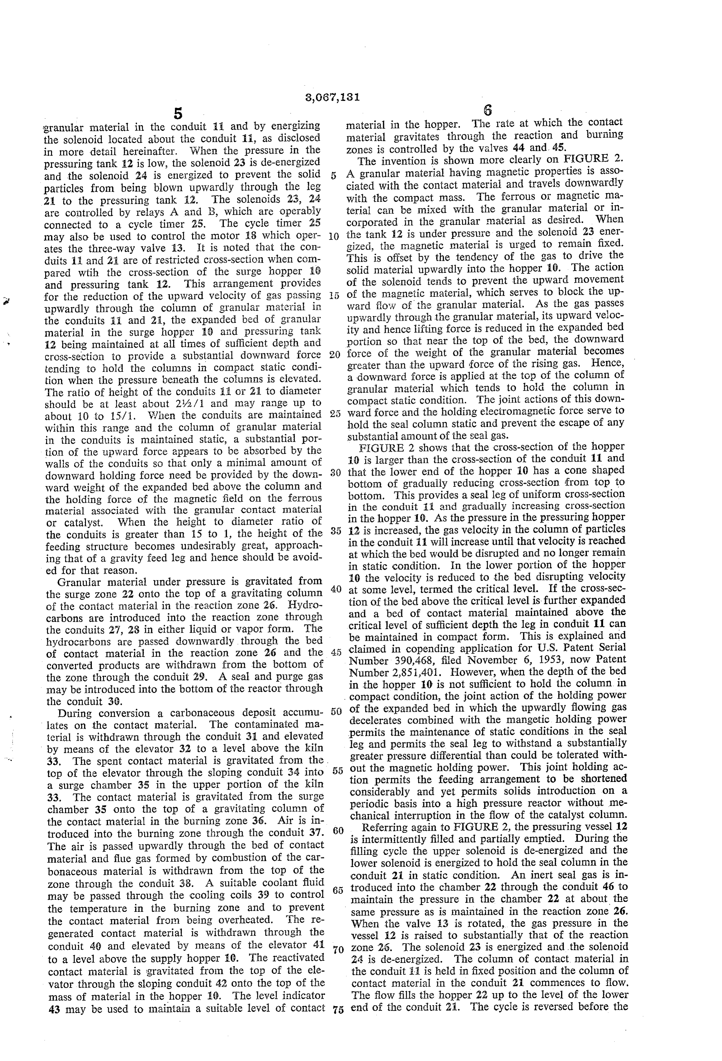
granular material in the conduit 1 and by energizing material in the hopper. The rate at which the contact the Solenoid located about the conduit i, as disclosed material gravitates through the reaction and burning in more detail hereinafter. When the pressure in the zones is controlled by the valves 44 and 45. pressuring tank A2 is low, the solenoid 23 is de-energized The invention is shown more clearly on FIGURE 2. and the solenoid 24 is energized to prevent the solid 5 A granular material having magnetic properties is asso particles from being blown upwardly through the leg ciated with the contact material and travels downwardly 2 to the pressuring tank 2. The solenoids 23, 24 with the compact mass. The ferrous or magnetic ma are controiled by relays A and B, which are operably terial can be mixed with the granular material or in connected to a cycle timer 25. The cycle timer 25 corporated in the granular material as desired. When may also be used to control the motor 8 which oper O the tank 2 is under pressure and the Soleioid 23 ener ates the three-way valve A3. It is noted that the con gized, the magnetic materiai is urged to remain fixed. duits 11 and 2i are of restricted cross-section when con This is offset by the tendency of the gas to drive the pared wtih the cross-section of the surge hopper 18 solid material upwardly into the hopper 10. The action and pressuring tank 12. This arrangement provides of the solenoid tends to prevent the upward movement e for the reduction of the upward velocity of gas passing of the magnetic material, which serves to block the up upwardly through the column of granular material in ward flow of the granular material. As the gas passes the conduits i and 25, the expanded bed of granular upwardly through the granular material, its upward veloc material in the surge hopper 18 and pressiring tank ity and hence lifting force is reduced in the expanded bed 12 being maintained at all times of sufficient depth and portion so that near the top of the bed, the downward cross-section to provide a substantial downward force 20 force of the weight of the granular material becomes greater than the upward force of the rising gas. Hence, tending to hold the columns in compact static condi tion when the pressure beneath the columns is elevated. a downward force is applied at the top of the column of The ratio of height of the conduits 1 or 21 to diameter granular material which tends to hold the column in should be at least about 2/2/1 and may range up to compact static condition. The joint actions of this down about 10 to 15/1. When the conduits are maintained ward force and the holding electromagnetic force serve to within this range and the column of granular material hold the seal column static and prevent the escape of any in the conduits is maintained static, a substantial por Substantial amount of the seal gas. FIGURE 2 shows that the cross-section of the hopper tion of the upward force appears to be absorbed by the
Walls of the conduits so that only a minimal amount of i0 is larger than the cross-section of the conduit 11 and downward holding force need be provided by the down bottom that the lower end of the hopper i0 has a cone shaped Ward weight of the expanded bed above the column and of gradually reducing cross-section from top to the holding force of the magnetic field on the ferrous bottom. This provides a seal leg of uniform cross-section material associated with the granular contact material in the conduit 1 and gradually increasing cross-section or catalyst. When the height to diameter ratio of in the hopper 19. As the pressure in the pressuring hopper the conduits is greater than 15 to 1, the height of the 35 12 is increased, the gas velocity in the column of particles feeding structure becomes undesirably great, approach in the conduit 1 will increase until that velocity is reached ing that of a gravity feed leg and hence should be avoid at which the bed would be disrupted and no longer remain ed for that reason, in static condition. In the lower portion of the hopper Granular material under pressure is gravitated from 10 the velocity is reduced to the bed disrupting velocity at Some level, termed the critical level. If the cross-sec the surge Zone 22 onto the top of a gravitating column 40 tion of the contact material in the reaction Zone 26. Hydro of the bed above the critical level is further expanded carbons are introduced into the reaction zone through and a bed of contact material maintained above the the conduits 27, 28 in either liquid or vapor form. The critical level of sufficient depth the leg in conduit 11 can hydrocarbons are passed downwardly through the bed be maintained in compact form. This is explained and of contact material in the reaction zone 26 and the 45 claimed in copending application for U.S. Patent Serial converted products are withdrawn from the bottom of Number 390,468, filed November 6, 1953, now Patent the Zone through the conduit 29. A seal and purge gas in Number 2,851,401. However, when the depth of the bed may be introduced into the bottom of the reactor through the hopper 10 is not sufficient to hold the column in the conduit 36. compact condition, the joint action of the holding power of the expanded bed in which the upwardly flowing gas
During conversion a carbonaceous deposit accumu 50 decelerates lates on the contact material. The contaminated ma combined with the mangetic holding power terial is withdrawn through the conduit 31 and elevated permits the maintenance of static conditions in the seal by means of the elevator 32 to a level above the kiln leg and permits the seal leg to withstand a substantially 33. The spent contact material is gravitated from the 55 greater pressure differential than could be tolerated with out the magnetic holding power. This joint holding ac top of the elevator through the sloping conduit 34 into tion permits the feeding arrangement to be shortened a Surge chamber 35 in the upper portion of the kiln 33. The contact material is gravitated from the surge considerably and yet permits solids introduction on a periodic basis into a high pressure reactor without me chamber 35 onto the top of a gravitating column of chanical interruption in the flow of the catalyst column. the contact material in the burning zone 36. Air is in 60 Referring again to FIGURE 2, the pressuring vessel 12 troduced into the burning zone through the conduit 37. is intermittently filled and partially emptied. During the The air is passed upwardly through the bed of contact filling cycle the upper solenoid is de-energized and the material and flue gas formed by combustion of the car lower solenoid is energized to hold the seal column in the bonaceous material is withdrawn from the top of the conduit 2i in static condition. An inert seal gas is in Zone through the conduit 38. A suitable coolant fluid troduced into the chamber 22 through the conduit 46 to may be passed through the cooling coils 39 to control maintain the pressure in the chamber 22 at about the the temperature in the burning zone and to prevent Same pressure as is maintained in the reaction zone 26. the contact material from being overheated. The re When the valve i3 is rotated, the gas pressure in the generated contact material is withdrawn through the vessel 12 is raised to substantially that of the reaction conduit 49 and elevated by means of the elevator 4 70 Zone 26. The solenoid 23 is energized and the solenoid to a level above the supply hopper 0. The reactivated 24 is de-energized. The column of contact material in contact material is gravitated from the top of the ele the conduit F1 is held in fixed position and the column of vator through the sloping conduit 42 onto the top of the contact material in the conduit 21 commences to flow. mass of material in the hopper 10. The level indicator The flow fills the hopper 22 up to the level of the lower 43 may be used to maintain a suitable level of contact 75 end of the conduit 21. The cycle is reversed before the
Page 7
hopper 12 is emptied of contact material and the level gas, in passing through the column of solids, removes in the hopper is rapidly raised to the bottom of the con the fine particles of magnetic steel and they are collected duit 11. The contact material is gravitated from the in the bottom of the separator 63. The fines are passed floor 47 of the chamber 22 through the pipes 48 to main tain a bed of solid material in the reaction zone 26. A through the conduit 72 to the lift feed tank 73. A lift gas is introduced into the tank 73 through the conduit portion of the solid material is fed into the central region 74 to lift the particles through the lift pipe 75. The gas of the reaction zone through the pipe 49 and directed by and particles are separated in the separator 76. The means of the conical baffle 50 and cylindrical baffle 5 gas is removed through the conduit 77 and and the par to form a curtain of falling contact material about the ticles are gravitated through the conduit 61 back to the discharge end of the liquid feed pipe 28. O mixer 60.
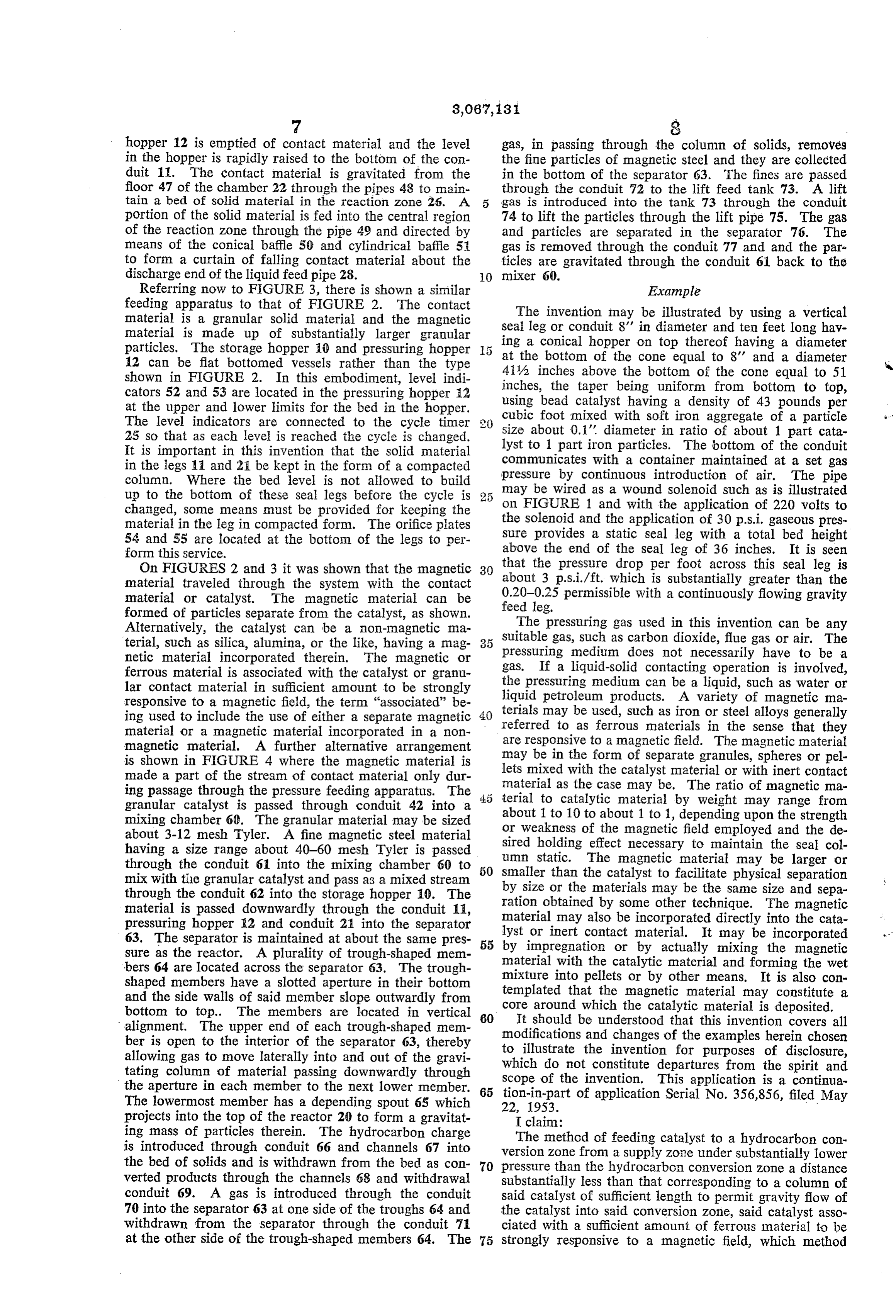
Referring now to FIGURE 3, there is shown a similar Example feeding apparatus to that of FIGURE 2. The contact The invention may be illustrated by using a vertical material is a granular solid material and the magnetic seal leg or conduit 8' in diameter and ten feet long hav material is made up of substantially larger granular ing a conical hopper on top thereof having a diameter particles. The storage hopper 10 and pressuring hopper 12 can be flat bottomed vessels rather than the type at the bottom of the cone equal to 8' and a diameter shown in FIGURE 2. In this embodiment, level indi 41% inches above the bottom of the cone equal to 51 cators 52 and 53 are located in the pressuring hopper 2 inches, the taper being uniform from bottom to top, at the upper and lower limits for the bed in the hopper. using bead catalyst having a density of 43 pounds per The level indicators are connected to the cycle timer 2 size cubic foot mixed with soft iron aggregate of a particle 25 so that as each level is reached the cycle is changed. about 0.1' diameter in ratio of about 1 part cata lyst to
It is important in this invention that the solid material communicates 1 part iron particles. The bottom of the conduit in the legs 1 and 21 be kept in the form of a compacted with a container maintained at a set gas column. Where the bed level is not allowed to build pressure by continuous introduction of air. The pipe up to the bottom of these seal legs before the cycle is may be wired as a wound solenoid such as is illustrated changed, some means must be provided for keeping the on FIGURE 1 and with the application of 220 volts to material in the leg in compacted form. The orifice plates the solenoid and the application of 30 p.s. i. gaseous pres sure provides a static seal leg with a total bed height 54 and 55 are located at the bottom of the legs to per form this service. above the end of the seal leg of 36 inches. It is seen On FIGURES 2 and 3 it was shown that the magnetic 30 that the pressure drop per foot across this seal leg is about 3 p.s.i./ft. which is substantially greater than the material traveled through the system with the contact 0.20-0.25 material or catalyst. The magnetic material can be feed leg. permissible with a continuously flowing gravity formed of particles separate from the catalyst, as shown. The pressuring gas used in this invention can be any Alternatively, the catalyst can be a non-magnetic ma Suitable gas, such as carbon dioxide, flue gas or air. The terial, such as silica, alumina, or the like, having a mag pressuring netic material incorporated therein. The magnetic or gas. If a medium does not necessarily have to be a liquid-solid contacting operation is involved, ferrous material is associated with the catalyst or granul lar contact material in sufficient amount to be strongly the pressuring medium can be a liquid, such as water or responsive to a magnetic field, the term “associated' be liquid petroleum products. A variety of magnetic ma ing used to include the use of either a separate magnetic 40 terials may be used, such as iron or steel alloys generally referred to as ferrous materials in the sense that they material or a magnetic material incorporated in a non are responsive to a magnetic field. The magnetic material magnetic material. A further alternative arrangement may be in the form of separate granules, spheres or pel is shown in FIGURE 4 where the magnetic material is made a part of the stream of contact material only dur lets mixed with the catalyst material or with inert contact material as the case may be. The ratio of magnetic ma ing passage through the pressure feeding apparatus. The 45 terial granular catalyst is passed through conduit 42 into a about to catalytic material by weight may range from 1 to 10 to about 1 to 1, depending upon the strength mixing chamber 60. The granular material may be sized or weakness of the magnetic field employed and the de about 3-12 mesh Tyler. A fine magnetic steel material sired holding effect necessary to maintain the seal col having a size range about 40-60 mesh Tyler is passed umn static. The magnetic material may be larger or through the conduit 61 into the mixing chamber 60 to 50 smaller than the catalyst to facilitate physical separation mix with the granular catalyst and pass as a mixed stream through the conduit 62 into the storage hopper 10. The by size or the materials may be the same size and sepa material is passed downwardly through the conduit 11, ration obtained by some other technique. The magnetic material may also be incorporated directly into the cata pressuring hopper 12 and conduit 21 into the separator lyst or inert contact material. It may be incorporated 63. The separator is maintained at about the same pres 55 by impregnation or by actually mixing the magnetic sure as the reactor. A plurality of trough-shaped mem material with the catalytic material and forming the wet bers 64 are located across the separator 63. The trough mixture into pellets or by other means. It is also con shaped members have a slotted aperture in their bottom templated that the magnetic material may constitute a and the side walls of said member slope outwardly from bottom to top. The members are located in vertical 60 core around which the catalytic material is deposited. It should be understood that this invention covers all alignment. The upper end of each trough-shaped mem modifications and changes of the examples herein chosen ber is open to the interior of the separator 63, thereby to illustrate the invention for purposes of disclosure, allowing gas to move laterally into and out of the gravi which do not constitute departures from the spirit and tating column of material passing downwardly through the aperture in each member to the next lower member. 65 Scope of the invention. This application is a continua tion-in-part of application Serial No. 356,856, filed May
The lowermost member has a depending spout 65 which 22, 1953.
projects into the top of the reactor 20 to form a gravitat I claim:
ing mass of particles therein. The hydrocarbon charge The method of feeding catalyst to a hydrocarbon con is introduced through conduit 66 and channels 67 into version zone from a supply zone under substantially lower the bed of solids and is withdrawn from the bed as con 70 pressure than the hydrocarbon conversion Zone a distance verted products through the channels 68 and withdrawal substantially less than that corresponding to a column of conduit 69. A gas is introduced through the conduit said catalyst of sufficient length to permit gravity flow of 70 into the separator 63 at one side of the troughs 64 and the catalyst into said conversion zone, said catalyst asso withdrawn from the separator through the conduit 71 ciated with a sufficient amount of ferrous material to be at the other side of the trough-shaped members 64. The 75 strongly responsive to a magnetic field, which method
Page 8
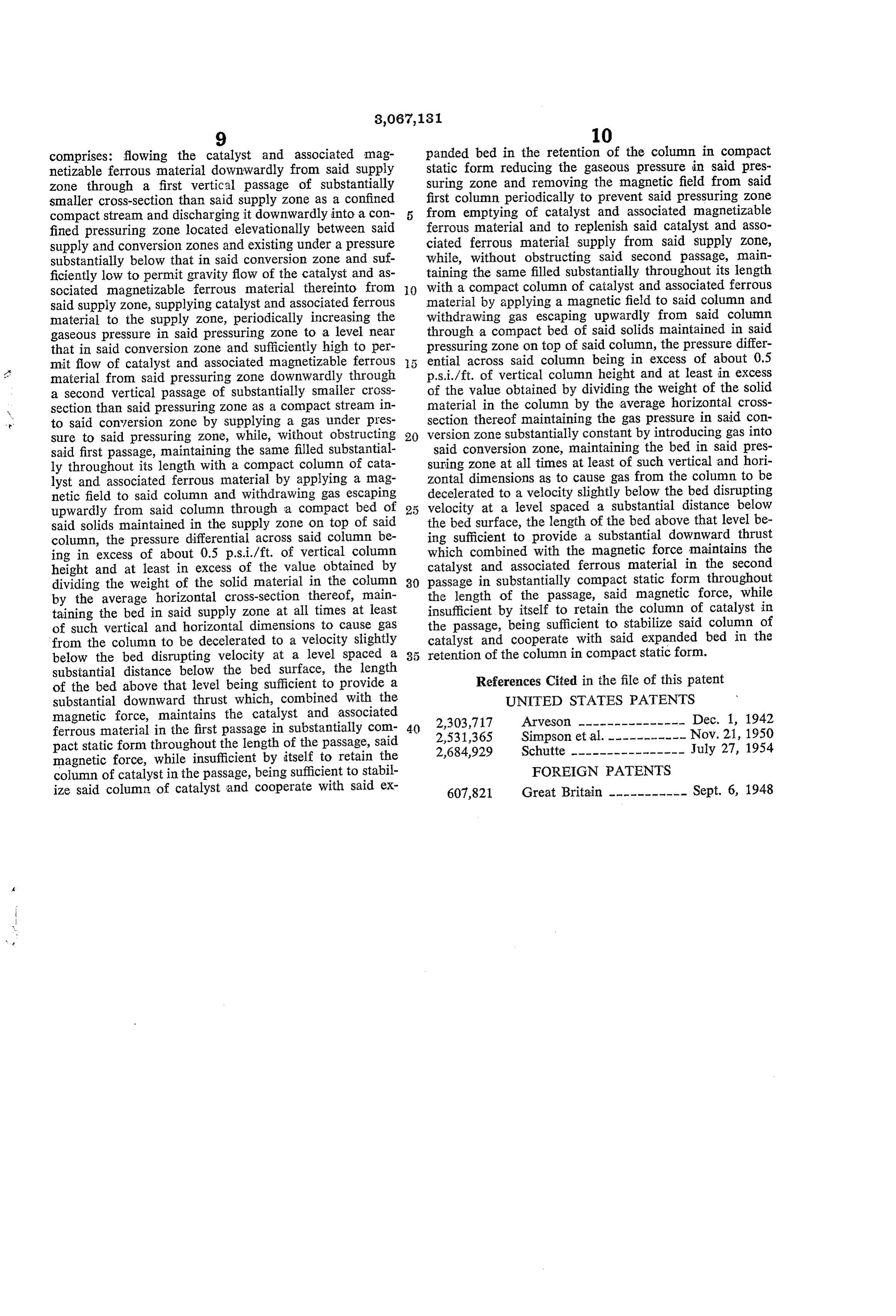
comprises: flowing the catalyst and associated mag panded bed in the retention of the column in compact netizable ferrous material downwardly from said supply static form reducing the gaseous pressure in said pres Zone through a first vertical passage of substantially Suring Zone and removing the magnetic field from said smaller cross-section than said supply Zone as a confined first column periodically to prevent said pressuring zone compact stream and discharging it downwardly into a con from emptying of catalyst and associated magnetizable fined pressuring zone located elevationally between said ferrous material and to replenish said catalyst and asso supply and conversion zones and existing under a pressure ciated ferrous material supply from said supply Zone, substantially below that in said conversion zone and suf while, without obstructing said second passage, main ficiently low to permit gravity flow of the catalyst and as taining the same filled substantially throughout its length sociated magnetizable ferrous material thereinto from O with a compact column of catalyst and associated ferrous said supply Zone, supplying catalyst and associated ferrous material by applying a magnetic field to said column and material to the supply Zone, periodically increasing the withdrawing gas escaping upwardly from said column gaseous pressure in said pressuring Zone to a level near through a compact bed of said solids maintained in said that in said conversion zone and sufficiently high to per pressuring zone on top of said column, the pressure differ mit flow of catalyst and associated magnetizable ferrous ential across said column being in excess of about 0.5 material from said pressuring zone downwardly through p.s.i./ft. of vertical column height and at least in excess a second vertical passage of substantially smaller cross of the value obtained by dividing the weight of the solid section than said pressuring zone as a compact stream in material in the column by the average horizontal cross to said conversion zone by Supplying a gas under pres section thereof maintaining the gas pressure in said con sure to said pressuring zone, while, without obstructing 20 version Zone substantially constant by introducing gas into said first passage, maintaining the same filled substantial said conversion zone, maintaining the bed in said pres ly throughout its length with a compact column of cata suring zone at all times at least of such vertical and hori zontal dimensions as to cause gas from the column to be lyst and associated ferrous material by applying a mag decelerated netic field to said column and withdrawing gas escaping to a velocity slightly below the bed disrupting upwardly from said column through a compact bed of 25 velocity at a level spaced a substantial distance below said solids maintained in the supply Zone on top of Said the bed surface, the length of the bed above that level be column, the pressure differential across said column be ing sufficient to provide a substantial downward thrust ing in excess of about 0.5 p.s.i./ft. of vertical column which combined with the magnetic force maintains the catalyst and associated ferrous material in the second height and at least in excess of the value obtained by passage dividing the weight of the solid material in the column 30 in substantially compact static form throughout by the average horizontal cross-section thereof, main the length of the passage, said magnetic force, while taining the bed in said supply Zone at all times at least insufficient by itself to retain the column of catalyst in of such vertical and horizontal dimensions to cause gas the passage, being sufficient to stabilize said column of from the column to be decelerated to a velocity slightly catalyst and cooperate with said expanded bed in the below the bed disrupting velocity at a level Spaced a retention of the column in compact static form. substantial distance below the bed surface, the length of the bed above that level being sufficient to provide a References Cited in the file of this patent substantial downward thrust which, combined with the UNITED STATES PATENTS magnetic force, maintains the catalyst and associated 2,303,717 Arveson --------------- Dec. 1, 1942 ferrous material in the first passage in substantially com 40 2,531,365 Simpson et al. ----------- Nov. 21, 1950 pact static form throughout the length of the passage, said 2,684,929 Schutte ---------------- July 27, 1954 magnetic force, while insufficient by itself to retain the column of catalyst in the passage, being sufficient to stabil FOREIGN PATENTS ize said column of catalyst and cooperate with said ex 607,821 Great Britain ----------- Sept. 6, 1948
Provenance
- Collection
- Cited prior art
- Original PDF
- patentimages.storage.googleapis.com →
- Filed
- 1961-03-27
- Pages
- 8
- Method
- pdftotext (the PDF's own text layer) + pdftoppm 300dpi page scans
- Source
- Google Patents bibliographic record
- Granted
- 1962-12-04
- Inventors
- Eric V Bergstrom; Socony Mobil Oil Co Inc
- Transcribed from
- patentimages.storage.googleapis.com →