patent · US3152926
Photoelectric transducer
13 October 1964
Page 1
Drawing sheet — no readable text.
Page 2
United States Patent Office 3,152,926 Patented Oct. 13, 1964
3,152,926 Each section has a metallic base 14, an intermediate
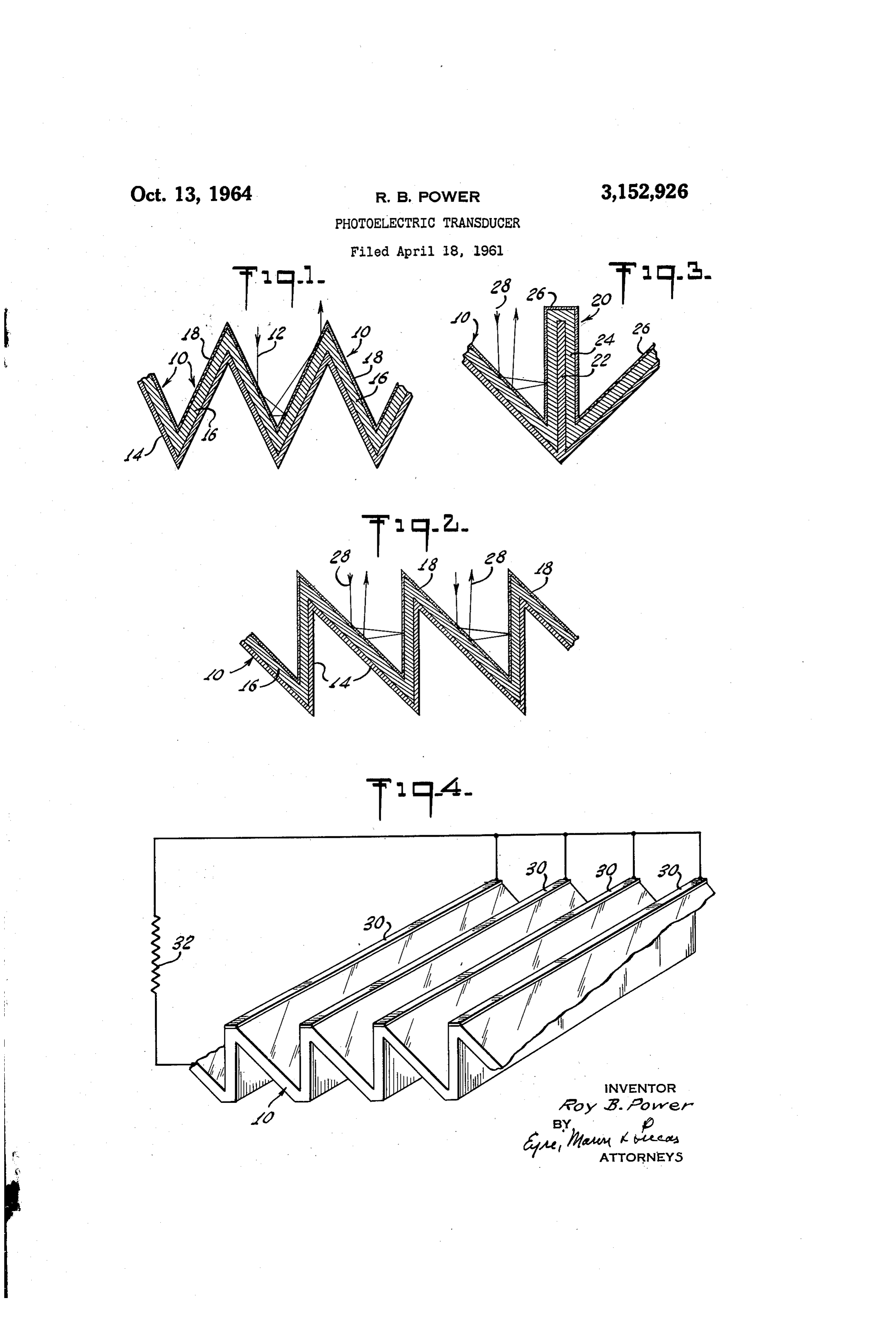
PHOTOELECTREC TRANSUCER layer 16 of photoelectric material, and an outer layer Roy B. Power, Madison, N.J., assignor to Tung-Sol such as tin oxide 18 which must be both conductive Electric Inc., a corporation of Delaware and transparent. Layers 14 and 18 act as terminals for Filed Apr. 18, 1964, Ser. No. 193,753 the transmission of electrical power and connections are 3 Claims. (Cl. 136—89) made to these terminal layers for connection to a load which may be any type of utilization circuit. The photo
This invention relates to a photoelectric transducer for electric material 16 generates electric charge carriers the conversion of light into electrical energy. It has when light is incident upon its outer surfaces. These particular reference to the efficient conversion of light, 10 charge carriers pass to layers 14 and 18 and thereby pro such as solar radiation, directly into electrical power by duce a potential which generates an electric current when incidence upon a photoelectric cell. connected to a load.
Many types of photoelectric transducers have been The transducer shown in FIG. 2 is similar to that developed and used for the detection of light, its measure shown in FIG. 1 except that alternate cell sections are ment, and the conversion of light into electrical energy. vertical. The dihedral angle between the strips is about The present invention is not concerned with the details of 45°. The number of reflections depends in part upon the transducer but rather in the manner of arrangement the direction of the incident light. of the transducer components so as to absorb a greater In the transducer shown in FIG. 3 the strips 10 form a portion of the light energy and reduce the percentage of dihedral angle of 90 and an additional strip 20 is mounted reflected light. While the invention has been designed 20 in a vertical plane bisecting the angle between strips 10. for use at locations exposed to light from the sun, the in The added strips 20 are secured to the troughs formed vention will be described without particular reference to by the angle between strips 10 and extend above the the source of light energy. As used throughout the speci level of the upper junctions of strips 10. Each includes fication and claims, the term "light” refers to any type of a central conductive base strip 22, an intermediate layer photon energy, whether in the visible light range, the 24, and an outer transparent conductive layer 26. These ultraviolet, or the infrared. The range of frequencies layers are joined to similar layers in the other strips as which can be usefully employed by the transducer de shown in FIG. 3. A light ray 28 incident upon one of pends only upon the range and sensitivity of the trans the strips 10 is reflected to strip 20 and then back to ducer material. strip 10 thereby making three reflections before leaving Briefly, the new photosensitive array comprises rows 30 the array. It should be noted that one of these reflec of parallel sided cell sections, adjacent sections forming tions is approximately at right angles to strip 20 and therebetween a dihedral angle small enough to insure that thereby is capable of greater conversion efficiency than incident radiation will successively impinge upon a plu reflections where the angle of incidence is much less. rality of surfaces thereby increasing absorption and re The array shown in FIG. 4 is the same as that shown ducing energy wasted by reflection from the array. The in FIG. 2 except that additional metallic conductive strips cell sections are connected together physically and elec 30 have been added to the upper junctions of strips 10 trically and each section includes a transparent conduct and these and the lower junctions have been flattened. ing layer facing the light source, a metallic base layer, The strips 30 form additional terminals for connection to and a photosensitive material secured between the layers. 40 a load 32 and should be connected together as shown in Electrical conductors are connected to the transparent that figure. These strips increase the conversion effi conductive layer and to the metallic base layer for trans ciency by lowering the overall cell resistance and per fer of the electrical energy to a load. mitting greater current to flow through the circuit. For a better understanding of the present invention, It will be evident from the above description that a reference may be had to the following description taken 45 new array has been produced for photoelectric trans in connection with the accompanying drawings. ducers which is more efficient than prior art transducers FIG. 1 is a cross sectional view of a transducer array and in addition has lower internal resistance. representing one embodiment of the invention. The foregoing disclosure and drawings are merely FIGS. 2 and 3 are cross sectional views of alternative. illustrative of the principles of this invention and are forms of the transducer array. not to be interpreted in a limiting sense. The only limi FIG. 4 is an isometric view showing the appearance of 50 tations are to be determined from the scope of the ap an array having a form generally similar to that of FIG. 2 pended claims.
and including additional terminal strips for the collection I claim:
of electrical power. - 1. A photoelectric transducer comprising a metallic Referring now to FIG. 1, the transducer array is com conductive base including a first series of strips connected posed of a plurality of cell strips 10 mounted at an angle 55 to form a ridged surface, said surface including adjoining to each other of about 60. This construction produces strips disposed at an angle of substantially 90° to each a symmetrical series of ridges with the acute dihedral other, a second series of strips including a strip secured angles therebetween such that a light ray 12 which is in to each trough made by the strips of the first series, an . cident upon the transducer surface will be reflected at 60 the intermediate layer of photoelectrical material secured to . least three times before being directed back to the source. . top surface of said base and to both sides of each As energy is absorbed each time a direct or reflected ray strip in said second series, and a top layer of transparent strikes a cell section, the energy in the reflected ray pro conductive material secured to the outer surface of said gressively reduces and only a fraction of the energy of intermediate layer, said base and said top layer compris the incident ray is returned toward the source at the last 65 ing electrodes for transmitting electrical energy to a load. reflection. . .. ; 2. A photoelectric transducer as claimed in claim 1
Page 3
wherein said second series of strips are mounted sub- 2,919,298 Regnier et al. ---------- Dec. 29, 1959 stantially at right angles to the common plane including 2,989,641 Nicoll ----------------- June 20, 1961 the troughs. 3,015,590 Fuller ------------------ Jan. 5, 1962 3. A photoelectric transducer as claimed in claim 1 FOREIGN PATENTS wherein the outer edges of said second series of strips 5 extends beyond the plane defined by the upper edges of 560,652 Great Britain ----------- Apr. 13, 1944 said first series of strips. - 536,616 Canada ---------------- Jan. 29, 1957 References Cited in the file of this patent OTHER REFERENCES
UNITED STATES PATENTS Dale et al.: 14th Annual Power Sources Conference,
9 pages).
May 17, 18, 19, 1960, “High Efficiency Solar Cells" (4 2,214,283 Norwood -------------- Sept. 10, 1940 Acker et al.: Electronics, March 11, 1960 (pp. 167 2,904,612 Regnier ---------------- Sept. 15, 1959. 172).
Provenance
- Collection
- Cited prior art
- Original PDF
- patentimages.storage.googleapis.com →
- Filed
- 1961-04-18
- Pages
- 3
- Method
- pdftotext (the PDF's own text layer) + pdftoppm 300dpi page scans
- Source
- Google Patents bibliographic record
- Granted
- 1964-10-13
- Inventors
- Roy B Power; Tung Sol Electric Inc
- Transcribed from
- patentimages.storage.googleapis.com →