patent · US4422445
Inflation supported solar collector
27 December 1983
Page 1 — bibliographic record
United States Patent (19) (11) 4,422,445 Pelley 45) Dec. 27, 1983 (54) NFLATION SUPPORTED SOLAR 4,003,365 1/1977 Wiegand et al..................... 126/426 COLLECTOR 4,004,380 1/1977 Kwake ............................ 126/416 X
76) Inventor: Ronald L. Pelley, 760 E. Telegraph 4,151,830 5/1979 Crombie et al. . 126/426 X Rd., Fillmore, Calif. 93015 4, 160,443 7/1979 Brindle et al. ...................... 126/426 21 Appl. No.: 346,519 FOREIGN PATENT DOCUMENTS 22) Filed: Feb. 8, 1982 7539606 7/1977 France ................................ 126/426 Primary Examiner-Samuel Scott
Related U.S. Application Data Assistant Examiner-Randall L. Green 63 Continuation of Ser. No. 154,808, May 30, 1980, aban Attorney, Agent, or Firm-Jack C. Munro doned.
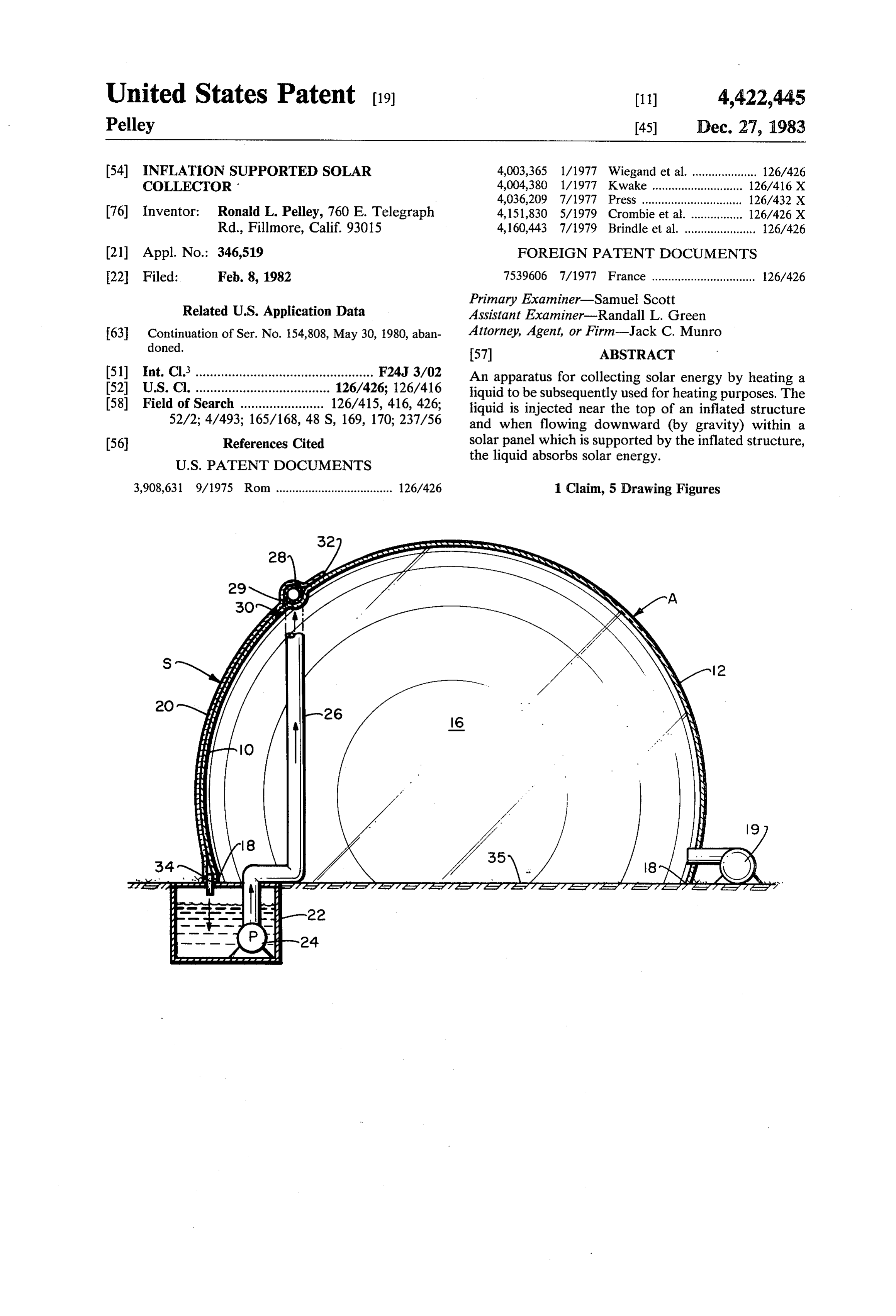
(51) Int. Cl.................................................. F24J 3/02 An apparatus for collecting solar energy by heating a (52) U.S. Cl. ..................................... 126/426; 126/416 liquid to be subsequently used for heating purposes. The 58) Field of Search ....................... 126/415, 416, 426; liquid is injected near the top of an inflated structure 52/2; 4/493; 165/168, 48 S, 169, 170; 237/56 and when flowing downward (by gravity) within a 56 References Cited solar panel which is supported by the inflated structure,
the liquid absorbs solar energy.
3,908,631 9/1975 Rom .................................... 126/426 1 Claim, 5 Drawing Figures
Page 2
Drawing sheet — no readable text.
Page 3
Drawing sheet — no readable text.
Page 4
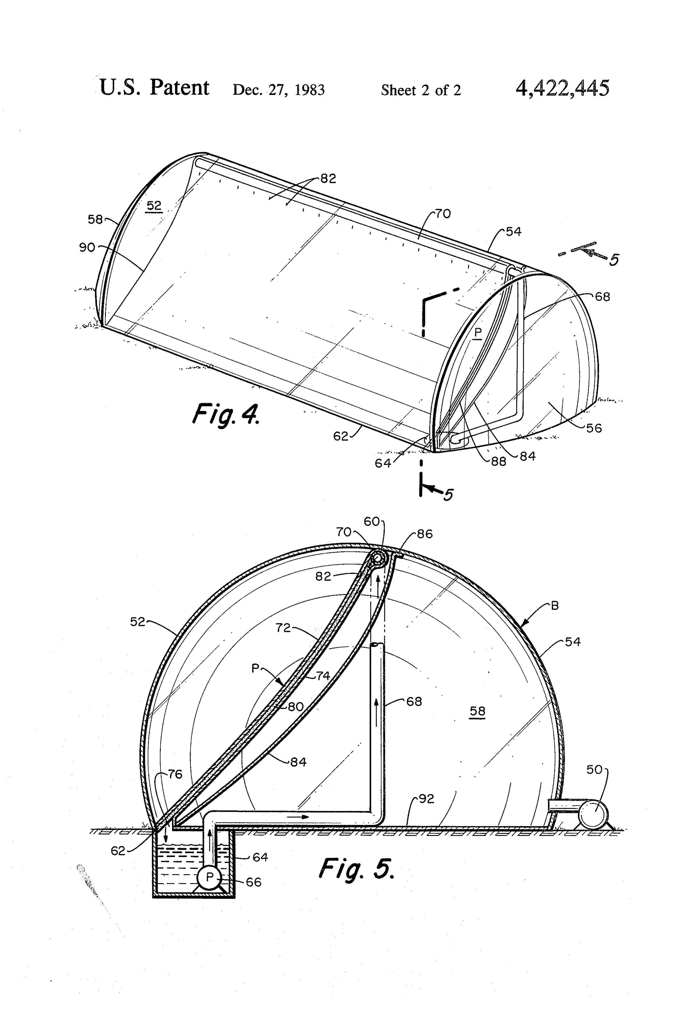
FIG. 4 is a perspective view of an alternate form of
ENFLATION SUPPORTED SOLAR COLLECTOR the solar collector of this invention; and FIG. 5 is a transverse, cross-sectional view taken
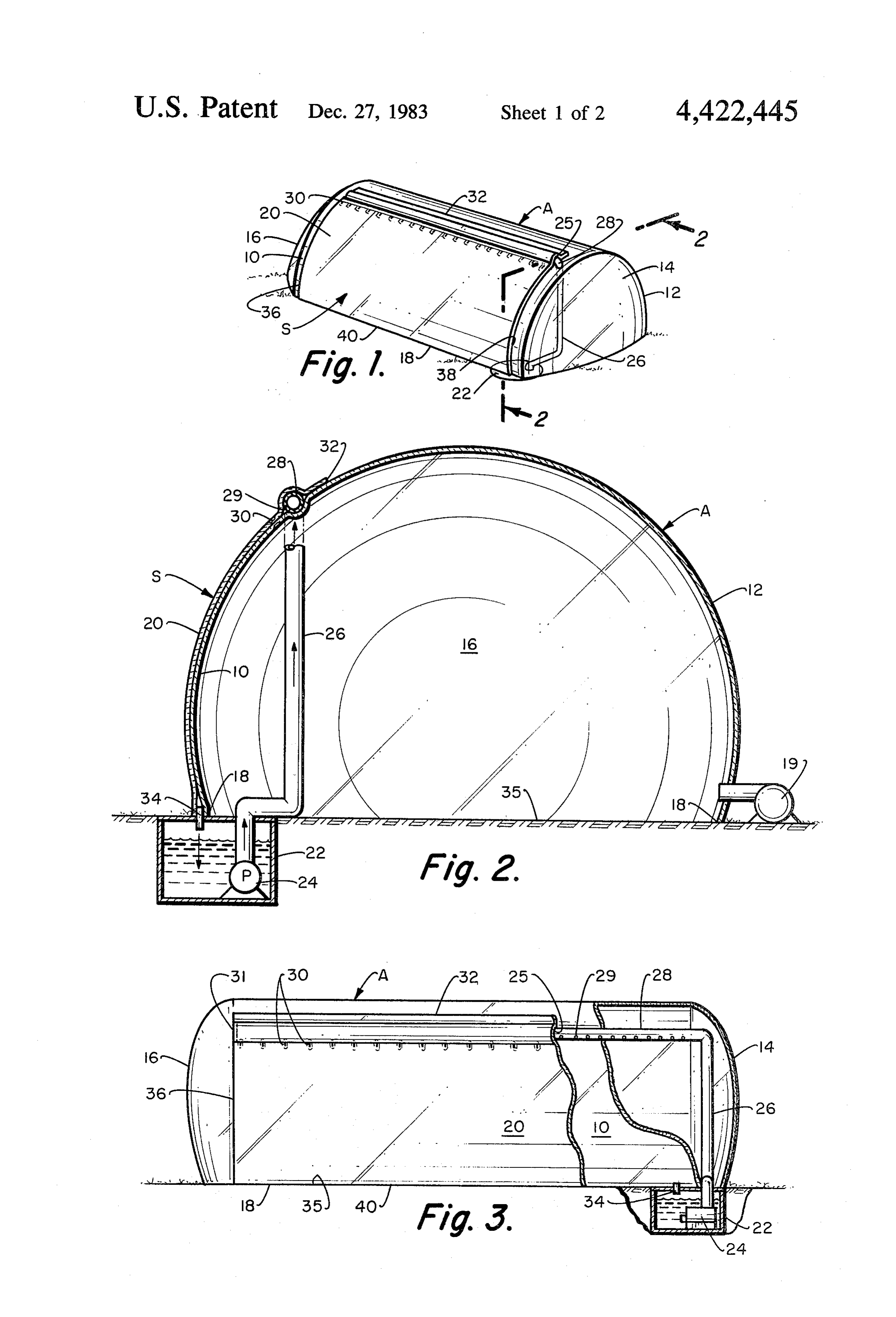
REFERENCE TO PRIORAPPLICATION along line 5-5 of FIG. 4 of the alternate form of the This application is a continuation of patent applica solar collector of this invention. tion Ser. No. 154,808, filed May 30, 1980, by the same BACKGROUND OF THE INVENTION title and by the same inventor, now abandoned. Referring particularly to the drawing, and more par BACKGROUND OF THE INVENTION ticularly to FIGS. , 2 and 3, there is shown a generally This invention relates generally to the field of solar O elongated inflatable assembly A embodying the instant collectors for conversion of solar energy to space heat invention.
inflatable
The solar collector assembly A includes an housing which has front and rear longitudinal ing and more specifically, to a solar collector which is walls 0 and A2 and
Supported by a fan inflated structure and which uses a attached to the groundend18 walls or 14 and 6, which are support structure in any liquid for the collection of solar energy. 15 conventional manner. An air blower 9 is used to sup This nation faces a major problem in conservation of energy, a problem commanding sharply increasing pri ply the pressurized air such that the assembly A may be inflated and erected. A sheet material film of flexible orities as petroleum feedstocks become scarce and alter material 20 is attached to the front assembly wall 0 at nate energy sources, such as nuclear power encounter the edges 32, 36, 38 and 40. Either, or both, the sheet 20 political resistance or technological problems. In addi 20 and tion, due to the rapidly rising energy costs of petroleum whichtheis front highly wall 10 should be made of a material absorbant to solar radiation. The two energy, alternate energy sources such as solar energy is sheets 10 and 20 constitute the energy absorption region receiving considerable attention. Although solar energy of the solar collector assembly A and is designated the is widespread and abundant, it is not without its prob solar panel S.
lems. For instance, for applications such as greenhouse 25 In the arrangement illustrated in FIG. 2, a pump 24 is heating, thin typical solar collector is generally too ex pensive to justify its use. Although several low cost located in a water storage tank 22, which is preferably insulated. Flexible tubing or piping 26 is connected to inflatable solar collectors have been proposed, they the pump 24 typically use air as the solar energy collecting medium. ing assembly and A, extends adjacent the apex of the hous then through a small opening 25 in the
As air has little inherent storage capacity, the designs 30 solar panel and connects to a perforated header pipe 28. are generally inapplicable for nighttime space or green The heater pipe 28 has a series of small distributed open house heating. ings 29 and is capped on one end 31. When the pump 24 SUMMARY OF THE INVENTION is turned on, the water flow is injected within a narrow chamber between sheets 10 and 20. As the water flows
The primary objective of the instant invention is to 35 downward due to gravity, the water absorbs solar en provide an efficient solar collector which is economical ergy. At the bottom of the solar panel S, the heated in providing thermal energy. water flows through a pipe 34 and back to the tank or Another objective of this invention is to provide a storage facility 22. The tank as illustrated is placed solar collector which can store the energy for later below the ground level 35. However, the tank 22 may usage. This is achieved by using a liquid to absorb the be located above the ground 35, but a pump (not shown) energy and a tank for storage of this energy. would be needed to pump the liquid from the bottom of Another objective of this invention is to provide a the solar panel S to the tank. Operationally, the pump 24 solar collector which is highly resistant to wind loads would generally be activated when the temperature of and which is not subject to damage caused by liquid the solar panel S exceeds the tank water temperature. freezing duging cold periods. 45 To support the header pipe, the solar collector sheets 10 This and other objectives are accomplished with the and 20 are bonded together forming several bond loca design of the instant invention whereby solar energy is tions 30.
collected and is used for heating or drying purposes, An additional use of the assembly A would be to use such as greenhouse, space, pool, or hot water heating. the space inside the assembly A as a greenhouse and The invention includes a generally elongated, inflatable, 50 grow plants or vegetables. For this usage, the solar tubular, film (sheet material) housing. A fan for inflating panel sheets 10 and 20 should consist of clear plastic and the housing is used to provide the fluid pressure for the solar collector liquid should be transparent to the supporting the structure. A liquid typically water, is solar energy spectrium required for plant growing. pumped upward to near the top of the flexible housing However, materials, such as copper chloride, can be through piping or tubing. The liquid is then injected 55 added to the water for absorbing the solar energy spec from the pipes to the internal portion of a solar panel. trium which is not required for plant growth. Another As the liquid flows downward by gravity through the optional use of the solar collector assembly A is for solar panel, the liquid absorbs solar energy. For a typi water chilling. For this function, the liquid is circulated cal application, the liquid is stored and used later when through the solar panel S during nighttime. the energy demand is greater. 60 A variation of the inflatable solar collector design is illustrated in FIGS. 4 and 5. The advantage of this de
BRIEF DESCRIPTION OF THE DRAWING sign is that it results in greater solar collection efficiency FIG. 1 is a perspective view o4 the solar collector of through providing solar panel insulation by means of an the subject invention in the inflated configuration; air space both on the front and back of the solar panel. FIG. 2 is a front view of the solar collector taken 65 As illustrated in FIGS. 4 and 5, a blower 5 is used to along line 2-2 of FIG. 1; provide the pressurized air for inflating the solar collec FIG. 3 is a transverse, partly in cross-section, view of tion assembly B. The assembly B has front and back the solar collector of this invention; longitudinal walls 52 and 54 and end walls 56 and 58. A
Page 5
solar panel P is attached to the top of the assembly B at monly used in packaging. The plastic trapped air insu position 60 and to the ground plane 62. From the tank lating material could be attached to either or both the 64, the solar collection liquid 66 is pumped through a front or back faces of the solar panels. flexible pipe 68 upward to a header pipe 70 and injected The discussion of the solar collector assemblies between two flexible sheets of plastic film 72 and 74. shown in FIGS. 1-5 have been generally limited to Placed between the two films 72 and 74 is an absorbant those functions which relate to the collection and stor or weave material 80 whose purpose is to evenly distrib age of solar energy. For applications such as green ute the liquid as it flows inside the solar panel P. After houses or space heating, means of distributing (not flowing by gravity through the solar panel P, the solar shown) the collected solar energy to the desired loca energy collecting liquid is allowed to drain from the O tions would obviously be required. In addition, for opti solar panel P through an opening 76 and back into the mization of the collection of the solar energy, various storage facility 64. To support the header pipe 70 and controls, (not shown) such as thermostats can be effec the absorbant material 80, the solar panel sheets 72 and tively included with the solar assemblies. 74 are locally bonded together forming several bonding While the above description contains many specificit locations 82. 15 ies, these should not be construed as limitations on the A separate sheet of plastic 84 is attached to the top of scope of the invention, but rather as an exemplification the assembly 86 and to the ends of the solar panel 88 and of one preferred embodiment thereof. Many other vari 90, and also at the bottom of the solar panel 62. The ations are possible, for example, the position of where function of the plastic sheet 84 is to provide an insulat the solar panel Pattaches 60 to the assembly B can be ing dead air region behind the solar panel P. To equalize 20 varied to correspond to the sun position changes at the pressure across the insulating sheet 84, a small open various times of the year. Another variation would be ing, (not shown) may be added to the insulating sheet to bleed off some of the heated air inside the assemblies, 84. A separate plastic sheet 92 is laid above the ground said heated air to be used for daytime space heating. plane or support structure and is used to prevent mois What is claimed is:
ture from being sucked from the ground and reducing 25 1. A solar energy collecting apparatus comprising: the solar collection efficiency. a thin, flexible walled housing; The front wall of the solar assembly B should be an air blower connected to said housing, said air made of a material which is transparent to solar radia blower to inflate said housing forming a rigid tion, i.e., clear plastic. In addition, one or more of the walled structure, with said housing located on a sheets 72, 74 and 80 which make up the solar panel P 30 supportive surface said housing forming a totally should be of a material which is highly absorbant to enclosed chamber, said rigid walled structure hav solar radiation. ing an interior surface and an exterior surface, said The solar panels S and P as illustrated in FIGS. 1 interior surface defining the extremity of said to through 5 were designed to be lightweight and of sim tally enclosed chamber;
ple construction. However, the inflatable structures A 35 a strip of sheet material mounted on a portion of said and B can also be used to support heavier and more exterior surface of said rigid walled structure, a complex solar panels. For example, assuming a solar narrow chamber being formed between said strip collector assembly with a floor area of 1,000 square feet, and said exterior surface, said strip having a top (i.e., 100 ft. x 10 ft), and a common inflation fan which edge and a bottom edge, said top edge located a has a pressure capability of 0.5 inches of water, the total substantial distance from said supportive surface; lifting force on the assembly is over 2,500 pounds. With a liquid inlet pipe mounted within said narrow cham lifting forces of this magnitude, the inflatable assemblies ber, said liquid inlet pipe located at said top edge; A or B can be used to support heavier solar panels, such a reservoir, said reservoir to contain a liquid; means as rigid or semi-rigid solar panels. connecting said liquid inlet pipe to said reservoir; As discussed previously, a plastic film 84 is used to 45 and provide an insulating dead air region behind the solar a discharge opening attached to said bottom edge panel P. An alternate means, (not shown) of insulating connecting with said narrow chamber, said liquid the solar panels P or S would be to use two or more to be conducted through said inlet pipe into said sheets of plastic which are locally bonded together and narrow chamber and through said discharge open in which a matrix of air pockets are trapped between the 50 ing into said reservoir.
plastic sheets. This is similar to a material which is com
Provenance
- Collection
- Cited prior art
- Original PDF
- patentimages.storage.googleapis.com →
- Filed
- 1982-02-08
- Pages
- 5
- Method
- pdftotext (the PDF's own text layer) + pdftoppm 300dpi page scans
- Source
- Google Patents bibliographic record
- Granted
- 1983-12-27
- Inventors
- Ronald L. Pelley
- Transcribed from
- patentimages.storage.googleapis.com →