patent · US3586291
Means for controlling fluid flow
22 June 1971
Page 1 — bibliographic record
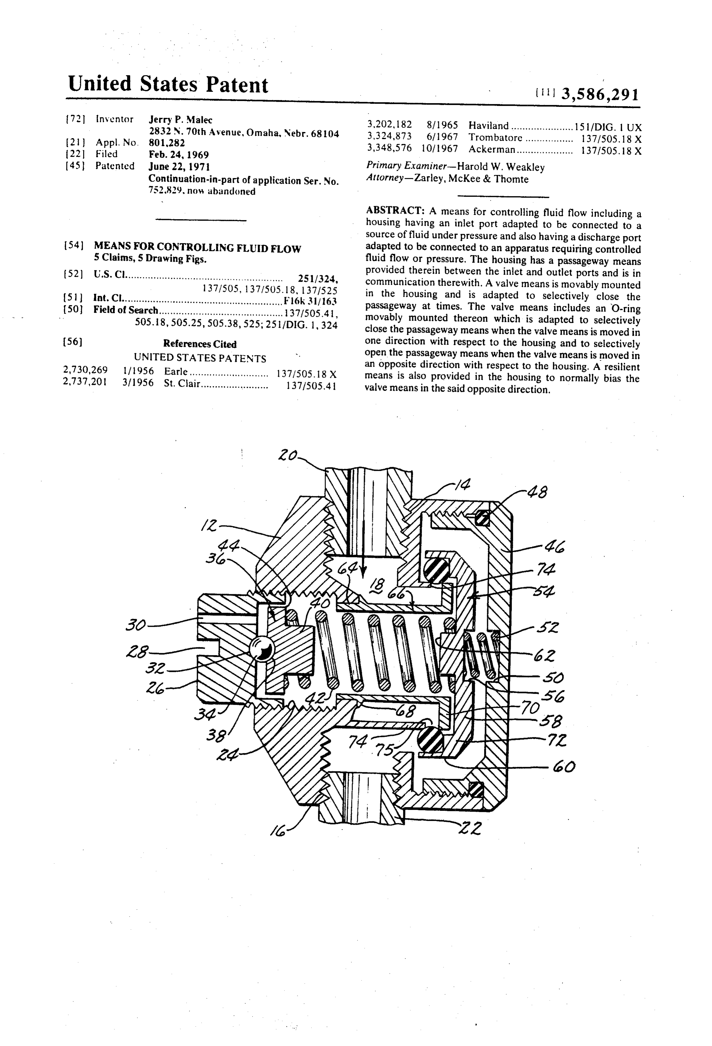
United States Patent (1113,586,291 72 inventor Jerry P. Malec 3,202, 182 8/1965 Haviland...................... 15 l/DIG. UX 2832 N. 70th Avenue, Omaha, Nebr. 68104 3,324,873 6, 1967 Trombatore. 137 1505.18 X (2) Appl. No. 801,282 3,348,576 101 l967 Ackerman.................... 37.1505, 18 X
(45. Patented June 22, 1971 Primary Examiner-Harold W. Weakley Continuation-in-part of application Ser. No. Attorney-Zarley, McKee & Thomte 752,829, now abandoned
ABSTRACT: A means for controlling fluid flow including a housing having an inlet port adapted to be connected to a source of fluid under pressure and also having a discharge port 54) MEANS FOR CONTROLLING FLUID FLOW adapted to be connected to an apparatus requiring controlled 5 Claims, 5 Drawing Figs. fluid flow or pressure. The housing has a passageway means 52) U.S. Cl........................................................ 251/324, provided therein between the inlet and outlet ports and is in 1371505, 137 1505. 18, 1371525 communication there with. A valve means is movably mounted 51 int. Cl......................................................... F6k 311 163 in the housing and is adapted to selectively close the 50 Field of Search............................................ 37.1505.41, passageway at times. The valve means includes an O-ring 505. 8,505.25,505.38,525; 25l/DIG. 1,324 movably mounted thereon which is adapted to selectively close the passageway means when the valve means is moved in 56) References Cited one direction with respect to the housing and to selectively UNITED STATES PATENTS open the passageway means when the valve means is moved in 2,730,269 l 1956 Earle............................ 137/505. 8 X an opposite direction with respect to the housing. A resilient 2,737,201 3/1956 St. Clair........................ 137.1505.41 means is also provided in the housing to normally bias the valve means in the said opposite direction.
Page 2
Drawing sheet — no readable text.
Page 3
A further object of this invention is to provide a pressure
MEANS FOR CONTROLLING FLUIDFLOW regulator which eliminates the "hunting,' vibration and sing This a continuation-in-part application of my copending ap ing phenomena associated with conventional regulators. plication, Ser. No. 752,829 filed Aug. 15, 1968. A further object of this invention is to provide a pressure Conventional pressure regulators usually employ approxi regulator which is insensitive to dirt, moisture, oil or vibration. mately 20 parts and are generally of the piston or diaphragm A further object of this invention is to provide a pressure type. The diaphragm-type pressure regulators are somewhat regulator which is economical of manufacture, durable in use less expensive than the piston-type regulators but cause a and refined in appearance.
restriction of the air flowing therethrough. The piston-type 10 These and other objects will be apparent to those skilled in pressure regulators are an improvement over the diaphragm the art.
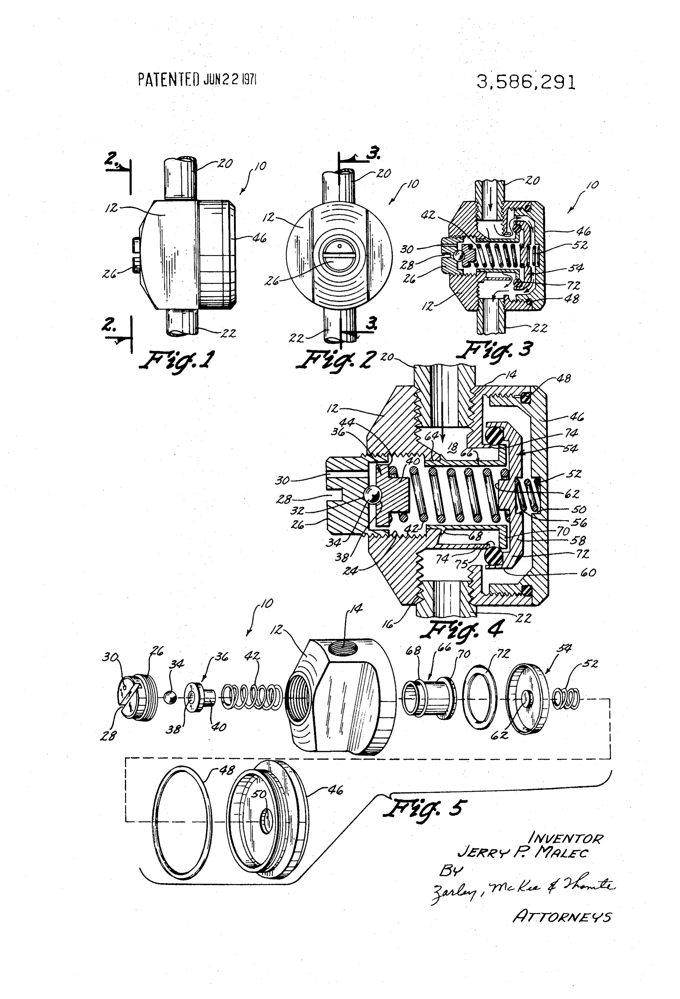
type regulators but are more expensive to manufacture. The This invention consists in the construction, arrangements, parts in a diaphragm regulator which are subjected to extreme and combination of the various parts of the device, whereby wear are the diaphragms and the poppet seals. The parts in the the objects contemplated are attained as hereinafter more piston-type pressure regulators which are exposed to extreme 15 fully set forth, specifically pointed out in the claims, and illus wear are the seals, pistons, cylinder walls and poppet seals. trated in the accompanying drawings in which: Pressure regulator is accomplished in most spring-balanced FIG. 1 is a side elevational view of the device; type regulators by balancing the downstream or regulated air FIG. 2 is a top view of the device; against the large spring that is adjusted to various compression FIG. 3 is a sectional view of the device as seen along lines values as are required. The diaphragm or piston is the medium 20 3-3FIG.
of FIG. 2;
4 is a sectional view similar to that of FIG. 3 except usually acted upon by the regulated air and the spring. When the regulated air and the spring are in equilibrium, the air con thatFIG.
the valve means is illustrated in a closed position; and 5 is an exploded perspective view of the device of this trolled by the poppet or fill valve is shut off to the downstream side of the regulator. Usually a spring of the right "K" weight invention.
The device of this invention is generally designated by the for a value of pressure to be regulated is necessary to provide 25 reference numeral 10 and includes a housing 12 having an maximum movement of the throtte valve for differences in in inlet port crements of regulated pressure. The throttle valve areas in discharge port means. 14 provided at one end thereof and a both of the piston and diaphragm-type regulators is quite small means provided at the other end thereof. The numeral 18 generally designates a passageway formed in hous in relation to the size of the regulator itself. Additionally, the ing 12 between the ports 14 and 16. A suitable conduit 20 is flow rates of the conventional regulators are not completely shown to be threadably secured in the inlet port 14 while a satisfactory in relationship to their size and the droop of the suitable conduit 22 is shown to be threadably secured in the regulators is also less than satisfactory. discharge port 16. Conduit 20 would be connected to a source The pressure regulator disclosed in applicant's copending of fluid such as air under pressure while the conduit 22 would application has been found to be very efficient in operation be connected to an apparatus requiring controlled or regu but the action of air on the O-ring therein sometimes result in 35 lated fluid pressure.
a variance in the regulated pressure and such variance is over Housing 12 is provided with an internally threaded opening come by the device disclosed herein. 24 which threadably receives an adjustment screw 26 having a Therefore, it is a principal object of this invention to pro slot 28 formed in its outer end. Screw 26 is also provided with vide a means for controlling fluid flow. an aspirator port 30 formed therein and extending A further object of this invention is to provide a flow sensor 40 therethrough as seen in FIG. 4. The inner end of the screw 26 mechanism. is provided with a recess portion 32 which partially receives a A further object of this invention is to provide a means for ball 34 therein. The numeral 36 generally designates a guide controlling fluid flow, namely a pressure regulator, which has provided at the inner end of the screw 26 and having a only approximately one-half the number of parts of the con 45 recessed portion 38 formed therein which partially receives ventional regulators. the ball 34. Guide 36 is provided with an inwardly extending A further object of this invention is to provide a pressure shank portion 40 as best seen in FIG. 4. A spring means 42 regulator which is many times more sensitive than conven embraces the shank portion 40 and engages the shoulder 44 of tional regulators of comparable size and flow. guide 36 and extends inwardly therefrom. A further object of this invention is to provide a pressure 50 A cap 46 is threadably mounted on the bottom of the hous regulator which has a throttle valve area of approximately 50 ing 12 and has an O-ring 48 provided thereon to effectively to 100 times the size of the throttle valve areas of regulators of seal the interior of the housing 12 from the atmosphere. The the same physical size but of conventional design. inside surface of cap 46 is provided with a recess portion 50 A further object of this invention is to provide a means for which receives one end of a spring means 52 extending in controlling fluid flow which is small in size but has a very high 55 wardly therefrom. The numeral 54 generally refers to a valve flow rate. means having a recessed portion 56 formed in its outer end A further object of this invention is to provide a pressure which receives the other end of the spring means 52. Valve regulator which achieves the same results as conventional means 54 includes a base portion 58 and a peripheral skirt regulators but which is much smaller in physical size. portion 60 extending inwardly therefrom as best illustrated in A further object of this invention is to provide a flow sensor 60 FIG. 4. Valve means 54 is provided with a shank portion 62 mechanism utilizing an O-ring which rolls into and out of en which extends inwardly from its inside surface and which is gagement with a dischargé port means. embraced by the other end of the spring means 42. A further object of this invention is to provide a pressure Housing 12 has an annular shoulder 64 formed therein into regulator wherein the internal passages are also larger than the which is press fitted one end of a sleeve 66. Sleeve 66 has a airline inside diameter. 65 peripheral ridge 68 extending outwardly therefrom which en A further object of this invention is to provide a pressure gages the shoulder 64 to limit the movement of the sleeve 66 regulator which is easily repaired without special tools. in the housing. Sleeve 66 is hollow and the spring means 42 ex A further object of this invention is to provide a pressure tends through the interior thereof. Sleeve 66 has a flange 70 regulator which has improved droop qualities. extending radially outwardly from the end thereof (FIG. 4) A further object of this invention is to provide a pressure 70 and is adapted to accommodate an O-ring 72 thereon which is regulator wherein the parts therein will be long wearing due to positioned between the outer edge of the flange 70 and the in the relatively small movement of the flow sensor valve. side surface of the skirt portion 60. The numeral 74 designates A further object of this invention is to provide a pressure a shoulder portion (FIG. 4) in housing 12 defining a regulator which eliminates the need of special balanced pop passageway 75 between it and flange 70. O-ring 72 is adapted pets for continuously bleeding the air or diaphragm chambers. 75 to close passageway 75 at times as illustrated in FIG. 4.
Page 4
The tension of the spring means 42 can be adjusted by The apparatus described herein, namely the flow sensor threadably rotating the screw 26 with respect to the housing valve, produces a greater opening of the control port than is 12. The inward movement of the guide 36 by the screw 26 possible with conventionally designed regulators. The instant results in the tension in the spring means 42 being increased apparatus can be substituted for any valve which is controlled and exerting a force against the valve means 54 towards the by fluid action that has a short stroke activated piston right as viewed in FIG. 4. FIG. 4 illustrates the O-ring 72 effec diaphragm or bellows as a source of movement of the valve tively sealing the passageway 18 and passageway 75 so that the mechanism. The concept of this apparatus can be used to pro conduits 20 and 22 are not in communication with each other. vide pilot-operated valves, high-pressure (3,000 p.s. i. or over) The spring means 52 normally urges the valve 54 to the left as valves that do not destroy the valve seats and seals when viewed in FIG. 4 which yieldably maintains the O-ring 72 in its O operating, and other valves used to expel water from air filter sealing engagement of the passageway 18. Adjustment of the trap mechanisms. The principal of the "rolling" O-ring can screw 26 with respect to housing 12 maintains the valve 54 in also be used to construct pumps and pressurizing devices. the desired position so that the predetermined volume of fluid Thus it can be seen that a vastly superior means for con may pass from the conduit 20, into passageway 6 and into 5 trolling fluid flow has been provided which achieves all of its stated objectives.
conduit 22. FIG. 3 illustrates the relationship of the com Some changes may be made in the construction and ar ponent parts of the device when the valve means 54 has been rangement of my Means For Controlling Fluid Flow without moved to the right due to the force of the spring means 42. As departing from the real spirit and purpose of my invention, valve means 54 is moved to the right as viewed in FIG. 3, the
O-ring 72 is rolled out of sealing engagement with respect to 20 formsitofisstructure and my intention to cover by my claims any modified or use of mechanical equivalents which may the shoulder 74 and the flange 70 so that air may pass through be reasonably included within their scope. the device in the manner illustrated by the arrows in FIG. 3. It | claim:
can be appreciated that the air will also act on the right-hand 1. A means for controlling fluid flow, comprising, side or outer surface of the valve means 54 as it passes through a housing having inlet and outlet ports formed therein, said the device which results in a more efficient operation of the 25 inlet port adapted to be connected to a source of fluid valve means 54. The design of the housing 12 and sleeve 66 is pressure, said outlet port adapted to be connected to an such that the valve means 54 is substantially shielded from the apparatus requiring controlled fluid pressure, said hous incoming air to reduce any fluttering of the valve means which ing having a passageway means provided therein between might possibly otherwise occur. said inlet and outlet ports and being in communication From the foregoing description it can be seen that a means therewith, for controlling fluid flow and more particularly a pressure 30 a valve means movably mounted in said housing adapted to regulator has been provided which has only approximately selectively close said passageway means at times, said one-half the number of parts of the conventional regulators. valve means including an O-ring movably mounted The device disclosed herein provides a pressure regulator thereon and adapted to selectively close said passage way which is much more sensitive than the conventional regulators 35 means when said valve means is moved in one direction of comparable size and flow and provides a regulator which with respect to said housing and to selectively open said has a throttle valve area of approximately 50 to 100 times the passageway means when said valve means is noved in an size of the throttle valve areas of regulators of the same physi opposite direction with respect to said housing, cal size but of conventional design. The device disclosed said valve means including a base portion having a herein may be small in size but would still have a very high 40 peripheral skirt portion extending transversely therefrom flow rate. The device disclosed herein achieves superior which movably embraces said O-ring with said skirt por results as compared to the conventional regulators and may be tion causing said O-ring to roll upon itself on said valve constructed to a smaller scale than the conventional regula means as said valve means is moved, tors. It can also be seen that the flow sensor mechanism (valve and means normally biasing said valve means in said op means 54 and its associated structure) disclosed herein utilizes 45 posite direction.
on O-ring which rolls into and out of engagement with a valve 2. The means of claim 1 wherein said O-ring movably em seat means to close the passageway between the inlet and braces a sleeve means positioned in said passageway means. discharge ports. The mechanism described herein can obvi 3. The means of claim 2 wherein said housing includes op ously be used in other environments than pressure regulators posite ends, said passageway means being between said op and may be easily repaired without special tools. 50 posite ends, one of said ends being selectively threadably The device disclosed herein provides a regulator wherein closed by a cap means having inner and outer sides, an adjust the internal passages are all larger than the airline inside ment screw threadably movably, mounted in the outer end of diameter. The device disclosed herein has also been found to said housing and being movable towards and away from said exhibit improved droop qualities and eliminates the hunting, cap means, said adjustment screw having inner and outer vibration and singing phenomena associated with conven 55 ends, said housing means including a first spring means opera tional pressure regulators. The regulator disclosed herein is in tively engaging the inner end of said screw and extending sensitive to dirt, moisture, oil and vibration and are extremely therefrom, said valve means being positioned between said long wearing. screw and said cap means, said first spring means engaging In summary, it can be seen that an apparatus has been said valve means and normally biasing said valve means towards said cap means, said sleeve means partially embracing described wherein an O-ring 72 rolls across a "ring'-type ori 60 said fice 75 with both diameters in contact with the O-ring being first spring means and having a peripheral flange portion, the same. When pressure to be regulated is applied to the ap means, said flange portion and said housing defining said passageway paratus, it tends to have no effect to open the downstream said O-ring movably embracing said flange portion. 4. The means of claim 3 wherein a second spring means is port as the pressure to be regulated is raised. Only when spring positioned bias pressure is applied does the O-ring roll away from the ori 65 mally biasing between said valve means and said cap means nor fice 75 and regulation begins. said valve means in said one direction. When the O-ring 72 seats directly and evenly over the 5. The means of claim 3 wherein said screw has a bore formed therein extending therethrough, the interior of said "ring'-type orifice 75, increases in pressure act directly out sleeve against the O-ring tending not to roll it away from the pressure being in communication with said screw bore to permit source. Pressure fluctuating on the "high'-pressure side have 70 the interior of said sleeve to communicate with the at very little adverse effect on the regulated pressure in this con mosphere outside of said housing.
struction.
Provenance
- Collection
- Cited prior art
- Original PDF
- patentimages.storage.googleapis.com →
- Filed
- 1969-02-24
- Pages
- 4
- Method
- pdftotext (the PDF's own text layer) + pdftoppm 300dpi page scans
- Source
- Google Patents bibliographic record
- Granted
- 1971-06-22
- Inventors
- Jerry P Malec
- Transcribed from
- patentimages.storage.googleapis.com →