patent · US20110214593A1
Eco-friendly system and process for generating thermal energy from waste biomass
8 September 2011
Page 1 — bibliographic record
(19) United States (12) Patent Application Publication (10) Pub. No.: US 2011/0214593 A1
Roychoudhury et al. (43) Pub. Date: Sep. 8, 2011 (54) ECO-FRIENDLY SYSTEMAND PROCESS F23B 99/00 (2006.01) FOR GENERATING THERMAL ENERGY F23C 9/06 (2006.01) FROM WASTE BOMASS (52) U.S. Cl. ......... 110/345; 110/346; 110/215; 110/218; (76) Inventors: Prabir Kumar Roychoudhury, 110/255; 110/234; 110/210 West Bengal (IN); Sayan
Roychoudhury, West Bengal (IN) (57) ABSTRACT
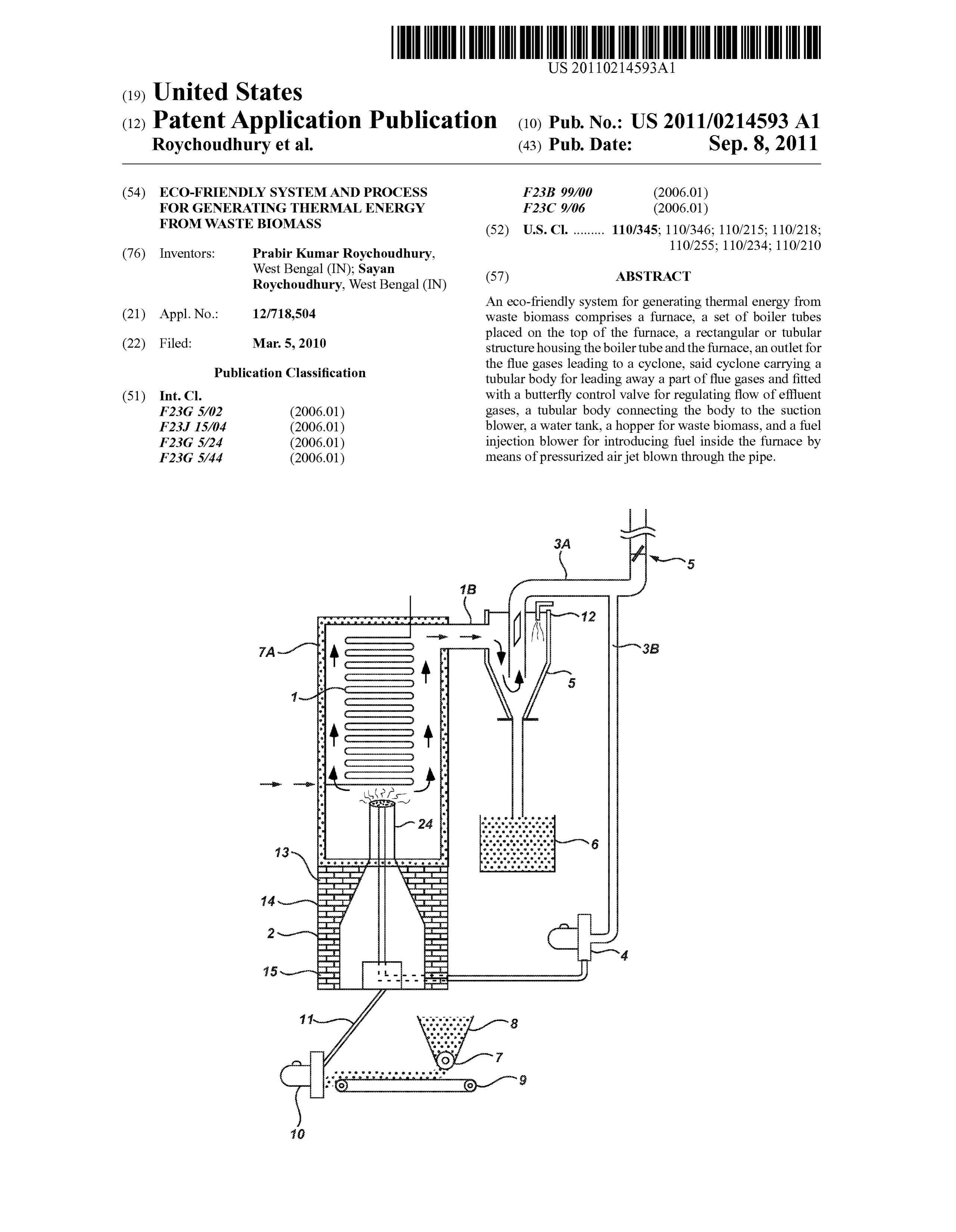
An eco-friendly system for generating thermal energy from (21) Appl. No.: 12/718,504 waste biomass comprises a furnace, a set of boiler tubes placed on the top of the furnace, a rectangular or tubular (22) Filed: Mar. 5, 2010 structure housing the boiler tube and the furnace, an outlet for the flue gases leading to a cyclone, said cyclone carrying a
Publication Classification tubular body for leading away a part of flue gases and fitted (51) Int. Cl. with a butterfly control valve for regulating flow of effluent F23G 5/02 (2006.01) gases, a tubular body connecting the body to the Suction F23. I5/04 (2006.01) blower, a water tank, a hopper for waste biomass, and a fuel F23G 5/24 (2006.01) injection blower for introducing fuel inside the furnace by F23G 5/44 (2006.01) means of pressurized air jet blown through the pipe.
Page 2
Drawing sheet — no readable text.
Page 3
US 2011/0214593 A1 Sep. 8, 2011
ECO-FRIENDLY SYSTEMAND PROCESS Double reheating has been introduced in order to increase the FOR GENERATING THERMAL ENERGY efficiency and in order to reduce the wetness of the exhaust FROM WASTE BOMASS steam from the LP turbine. The fuel includes coal, oil, straw and wood-pellets and the combustion system enables both
BACKGROUND single fuel as well as co-firing. The yearly biomass produc 0001. The present invention relates to a novel eco-friendly tion is planned to be 40,000 tons of wood pellets and 110,000 system for generating thermal energy from biomass, and a tons of straw pellets. This is 37% of the fuel input (energy) process therefor. More particularly the subject invention and will substitute about 95,000 tons of coal. The yearly deals with a system which generates considerable amount of potential for CO, reduction is o the order of 220,000 tons. heatenergy by burning renewable lignocellulosic agricultural 0013 Biomass for heat and power production has tradi and industrial wastes pretreated with a chemical, and emit tionally been used in grate fired and fluidized bed boilers. By negligible amounts of greenhouse gases and particulate mat the introduction of biomasspellets and milling plant, utiliza ters through its effluents. The system effectively uses waste tion of large volumes of biomass has been made for burners in heat for preheating treated fuel, thereby cutting down fuel direct-fired utility boilers.
consumption and is ideally Suited for running captive power 0014. However, despite the claimed efficiency, such boil plants in remote rural areas doing away with the systems ers use large Volume of coal, reserves of which are dwindling using fossil fuel with considerable emission of greenhouse fast all over the world. Besides, the menace of CO emission gases and environmental pollution by ejection of particulate as agreenhouse gas is still there, not to speak of the generation matters like fly ash. offly ash causing considerable environmental problems, even 0002 Coal as a fossil fuel is still widely used in thermal affecting fertility of arable land and contaminating water powerplants in large quantities, depleting its valuable reserve bodies adversely affecting marine life—as has been wit and posing danger of bringing about ecological disaster, not nessed in Orissa, West Bengal and Andhra Pradesh in India. to speak of the expenses involved. 00.15 Moreover, biomass in the form of wood pellets 0003 Nuclear energy is no doubt a source of clean would mean large scale felling of trees leading to deforesta energy, but the initial cost of setting up a reactor, safety tion, the effect of which is already affecting rainfall pattern in measures and disposal of nuclear wastes are major stumbling areas where forest cover is disappearing at an alarming rate, blocks, at least for a developing country like India. not to speak of loss offlora and fauna peculiar and character 0004 Hydro-electric power plants are ecologically safe istic of geographical location, for example in Costa Rica, offering clean energy, but erecting dams over rivers may Madagascar, Brazil, India and in various African countries, often pose problems, mainly due to silt deposition and lack of where replanting programmes are seldom executed in prac vigilance and maintenance. Large projects like this dam on tice.
the river Yangsikiang in China, river experts opine, is poten tially unsafe and unfit to withstand earthquakes. SUMMARY OF THE INVENTION 0005. Non-conventional energy like solar energy, wind energy, energy from tidal waves, geothermal energy and the 0016. The present invention aims at overcoming the draw like are some other sources of energy which are being utilized backs of the existing modes of thermal power generation by on an increasing scale in almost all countries in the world providing a system which is not only eco-friendly, but also having potential therefor. Here the major difficulty resides in uses lignocellulosic waste materials abundantly generated storage of energy generated, and distribution and utilization and available in an agrarian country like India. The system is of stored energy without description. Extensive research is capable of being installed even in remote rural areas, the only under progress, but it is likely to take Some more time before condition being availability of agricultural wastes to be used Such as Sources can be tapped properly. as fuel.
0006 Search for source of energy generation has been 0017. The principal object of this invention is to provide a going on for quite some time past and considerable Volume of novel eco-friendly system for generating thermal energy from work in this direction has been done and is still being carried biomass.
out. Some of the prior patents and allied publications are 0018. A further object of this invention is to provide a discussed below: novel system wherein waste lignocellulosic materials like 0007 U.S. Pat. No. 4,389,981 narrated a hydrogen gas saw dust, rice or wheat husk, bamboo dust and chips, jute injector system for internal combustion engine. Stick, waste hemp, sisal and jute, dried leaves, straw, lumps of 0008 U.S. Pat. No. 4,465,455 described start up/shut waste wood, etc. are used as fuel for running a specially down for a hydrogen gas burner and a hydrogen gas burner designed furnace, achieving a thermal efficiency in excess of was described in the U.S. Pat. No. 4,421,474. 98%.
0009 U.S. Pat. No. 4,826,581 dealt with controlled pro 0019. A still further object of the subject invention is to cess for the production of thermal energy from gases and provide a novel eco-friendly system wherein the fuel intro apparatus useful therefor. duced is a chemically treated one which helps in maintaining 0010 U.S. Pat. No. 4,936,961 described a method for the fuel in a fluidized condition under influence of a pressur production of a fuel gas. ized airjet, achieving an enhanced temperature in the range of 0011 U.S. Pat. No. 5,149,407 disclosed a process and 650° C. to 800° C.
apparatus for the production of fuel gas and the enhanced 0020. Another object of this invention is to provide a sys release of thermal energy from Such gas. tem which generates Superheated Steam in situ and in turn 0012. In a recent development, a Denmark based com produces water gas (i.e. mixture of CO and H2) by reacting pany, Burmeister & Wayne Energy A/S, has come out with with carbon (charcoal) formed under the reaction conditions super critical boilers, the characteristic feature of which is the prevailing in the furnace, thereby attaining a high temperature steam properties of 600° C. temperature and 305 bar pressure. of around 800° C.
Page 4
US 2011/0214593 A1 Sep. 8, 2011
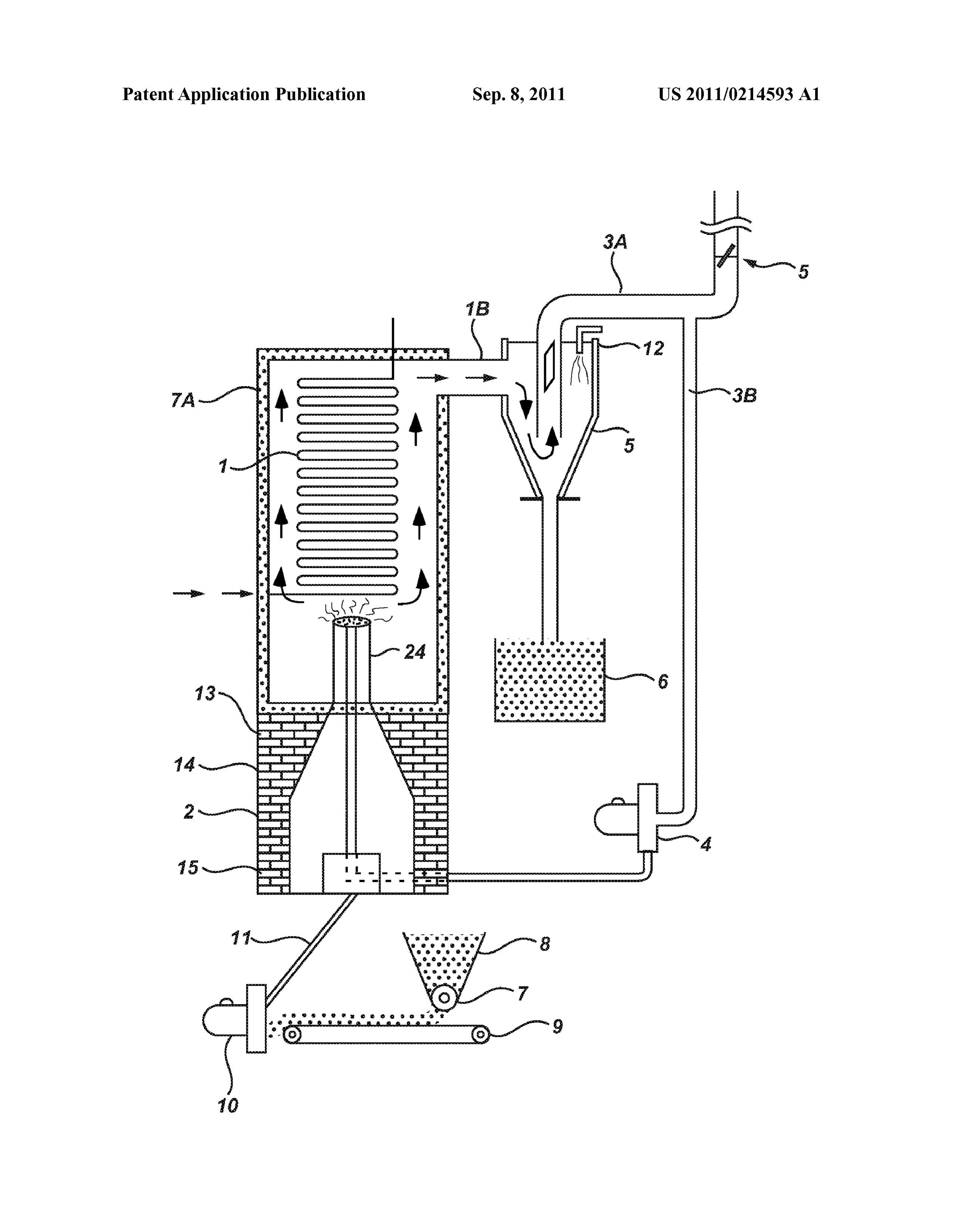
0021. Yet another object of this invention is to provide a 0034. 1 is the boiler tube, 1A is the insulation, 1B is the process for generating thermal energy with the help of the pathway for the effluent hot gases, 2 is furnace. 2A is the eco-friendly system as mentioned hereinbefore. tubular body on the upper part of the furnace, 3 is the cyclone, 0022. The foregoing objects are achieved by the present 3A is a double bent pipe connecting the cyclone and the invention which relates to a novel eco-friendly system for butterfly air controlling valve 5, simultaneously serving as the generating thermal energy from waste biomass, compris outlet for effluent gases, 3B is a by-pass pipe connecting the 1ng— outlet pipe and suction blower 4, 6 is the water tank, 7 is the 0023 (i) a furnace capable of generating and withstanding fuel flow control device, 8 is the fuel hopper, 9 is the conveyor, high temperature, round or tetragonal at the bottom and 10 represents fuel injection blower, 11 is the air inlet pipe tapering at the top assuming a conical shape and fitted at the carrying fuel, 12 is the spray mechanism for injecting water or top with a pipe; wet steam, 13 is the insulated wall of the mainstructure, 14 is 0024 (ii) a set of boiler tubes placed on top of the furnace; the device for recycling superheated steam and 15 is the 0025 (iii) a rectangular or tubular structure housing the opining in the furnace hearth for introducing fuel. boiler tube and the furnace, the said structure having insu 0035. As may be seen from the accompanying drawing, lated walls to prevent dissipation of heat; the conical furnace (2) carries a tube (14) running from grate 0026 (iv) an outlet for the flue gases leading to a cyclone to mouth which is meant for recycling Superheated Steam. The equipped with means for spraying water or wet steam, the furnace is made of a metal shell with a tubular structure at its said cyclone carrying a tubular body for leading away apart upper part, usually stainless steel of grade 310, capable of of flue gases and fitted with a butterfly control valve for withstanding high temperature. The inside Surface is clad regulating flow of effluent gases; with insulating firebricks. The mainstructure is usually tubu 0027 (v) a tubular body connecting the said body to the lar or cylindrical in shape, the lower part of which is brick Suction blower with a connection at the bottom of the built to accommodate the exterior part of the furnace, in furnace for blowing air?hot gases inside the burner Zone of conformity with its contour.
the furnace; 0036 Before feeding the furnace with the partially dried 0028 (vi) a water tank in which the downpipe of the waste biomass fuel, the raw mass is soaked in 20-30% solu cyclone is kept Submerged in water for trapping particulate tion of common salt for some time, Solution drained out and matter carried by the effluent gases from the furnace; the soaked mass is dried, usually under the Sun. During rainy 0029 (vii) a hopper for waste biomass used as fuel fitted season or with overcast sky, waste heat from the furnace may with a fluid flow control device, from which fuel is released be utilized for attaining desired level of moisture content. onto an endless conveyer belt for being led to the furnace Such utilization of waste heat adds to the overall economy of gate with the help of suction point of blower, and the system and renders the process further cost-effective. 0030 (viii) a fuel injection blower for introducing fuel 0037. The initial start up of the furnace may be done by inside the furnace by means of pressurized air jet blown burning low-grade coal, diesel or any other grade of fuel oil, through the pipe. including oil from Vegetative sources like Honge, Jatropha, 0031. The subject invention also pertains to a process for Rapeseed, green oil or mixture thereof. Once the furnace is lit generating thermal energy with the help of the novel system up, the entire burning operation may be continued with the as described herein, wherein one or more biomass selected help of the treated waste biomass exclusively, dispensing with from the group of saw dust, husk, bamboo dust, jute Stick, the use of fossil fuel.
waste jute, cotton waste, wooden blocks and the like renew 0038. The use of coal for power generation has pro able lignocellulosic agricultural and industrial waste materi nounced shortcomings— als are employed as fuel for generating heat on ignition to run 0039 (i) Thermal efficiency hardly rises beyond 40% even the furnace, characterized in that the said biomass or mixture when the units are operating in full Swing, thereof are soaked in common salt Solution and dried to 0040 (ii) Emission of fly-ash in exceedingly large volume 20-30% by weight, moisture content prior to being introduced often brings about ecological disaster, so much so at least into the furnace as fuel for burning, the effluent gas flow one thermal power station had to be shut down (in Mejia, through the cyclone is controlled by means of the butterfly air Bankura district, West Bengal) owing to damage caused to exhaust control device, for effecting heat recovery by intro arable land and water bodies;
ducing the hot flue gases inside the furnace to preheat the fuel 0041 (iii) Investmentina thermal power generation unit is and removal of suspended particulate matters is effected by exceedingly high with separate units for coal crushing, spraying fine stream of water or wet steam through the washing, beneficiation, drying, storing and conveying the sprayer and the lower end of the downpipe of cyclone is kept treated material to the furnace for burning. Moreover, Submerged in a water tank wherein the said particulate impu variation in the coal grade, its ash content, presence of rities collect, the said process achieving a thermal efficiency sulphur and such other factors affects/influences power in excess of 98%. generation per unit of fuel burnt. Emission control means like electrostatic precipitators are also expensive and add to
BRIEF DESCRIPTION OF THE DRAWING the overall cost of the set up.
0032 FIG. 1 is a schematic representation of the present 0042 (iv) Release of greenhouse gases is another negative system. aspect, and 0043 (v) Expert opine that with the present scale of con
DESCRIPTION OF THE INVENTION Sumption, world reserve of coal is depleting fast and is likely to last for another 3 to 4 decades.
0033. The present invention will now be described with 0044 Hydroelectricity undoubted affords a clean energy, the help of the illustrative drawing accompanying this speci but is seasonal as it depends entirely on the level of water in fication wherein— the flowing rivers or reservoirs artificially created for ensur
Page 5
US 2011/0214593 A1 Sep. 8, 2011
ing steady flow of water to run the turbines. With a normal and H. Moreover, when excess heated Steam is recycled level of rainfall, there is satisfactory generation of electricity through a red-hot iron tube, there is produced hydrogen gas during monsoon or a couple of months following it. During having much higher calorific value, —which in all probability Summer months Volume of water Supply dwindles and con contributes to the Surge in the temperature rise. sequently power generation is affected. In the event of 0053. Design of the furnace and the improved burning drought, power generation may even come to a halt. system in accordance with this invention play a vital role and 0045. On the contrary, the novel system of this invention may be considered to be key factors. Furnace chamber is to be utilizes vegetative wastes like agricultural waste materials made of a metal capable withstanding high temperature. including plants, shrubs and/or creepers of little or no com Stainless steel of appropriate grade (say 310) is preferred for mercial value as the biomass fuel. Experiments have shown the construction of the furnace, which is cylindrical at the that water hyacinth may be effectively used in admixture with bottom portion and conical on top, fitted with a long iron pipe saw dust or waste wood as the biomass. Coconut shell powder at the neck of the furnace, as may be seen in the drawing is another renewable source of biomass. In a predominantly accompanying this specification.
agricultural country like India, there is no dearth of waste 0054 The treated fuel selected from saw dust, bamboo biomass including, inter alia, rice and wheat husk, bamboo dust, jute stick particles, paddy husk, pieces of dried shrubs/ chips and dust, jute Sticks and the like, which entitles the aquatic plants (like water hyacinth), etc. with a residual mois system to be located even in remote, far flung, rural areas ture content of 20-30% is injected with high pressure air jet where electricity has remained a dream even after 6 decades into the furnace through an iron pipe. The fuel burns in a since attaining independence. Each unit will be capable of floating condition inside the furnace, creating a fluidized generating, say, 1 MW of power for use among rural popula bed for all intents and purposes. tion only. The entire array of plants and equipments is nomi 0055. Thermal value of the waste biomass materials nal in comparison with the conventional coal-based power referred to above usually varies between 3500 and 4000 Kcal generation units. per gram. In normal burning, these yield rather poor thermal 0046. It has surprisingly been found that the novel system value, thermal efficiency hardly exceeding 20%. On the con emits virtually no particulate impurities with the effluent trary, pre-treatment of the biomass with brine, drying of the gases, and there is negligible emission of greenhouse gases. treated biomass to a moisture content of 20-30% and burning The operation o the system also results in a valuable by the same with the high pressure air jet creating a fluidizedbed product, namely, high grade pure carbon black which is condition contribute to the attainment of thermal efficiency recovered from the bottom of the water tank (6). level beyond any reasonable expectation, exceeding 98%. —a 0047 Sprinkling fine spray of water or injecting wet steam level not achieved or reported heretofore anywhere In the into the effluent gases by means of the spray (12) effectively world.
reduces particle load thereof, and substantially removes 0056. The undernoted working data lend support to the greenhouse gases, thereby virtually eliminating all possibili statements made above:- ties of environmental pollution. 0057 (i) Pump capacity 36 M/hour: 0048. Another surprising aspect of this invention is its 0058. Density of thermal fluid 0.88 gm/cc, which reduced consumption of biomass fuel following the salt treat works out to 31,680 Kg./hour. ment with partial drying of the feedstock. 0059 (ii) Assuming efficiency of the pump to be 80%, 0049. The following examples give the details of working flow of thermal fluid is 25.344 Kg./hour. which are given by way of illustration and not by way of 0060 (iii) Specific heat of thermal fluid is 0.75 Calorie, limitation. and average rise in temperature from inlet to outlet is 28°
Example—1 0061 (iv) Average consumption of saw dust and wood lumps per hour—60 Kg.
0050. Originally the thermal fluid heater used a Diesel 0062 (v) 60 Kg. wood/saw dust (waste biomass) burner, consuming around 30 ltrs. of Diesel per hour, Per gives— working day spanning 8 hours, Diesel consumption was 0063. 25.344 Kg.x0.75x0.88—5.32.224 Kcal. or around 180 litres/diem, which received the temperature of the 8,870 Kcal per Kg.
thermal fluid ranging between 150° C. and 180° C. 0064. As mentioned hereinbefore thermal value of wood/ 0051. After switching over to waste biomass fuel, con saw dust is around 3500 to 4000 Kcal per Kg. and thermal sumption per diem has been found to be around 275 Kg. of efficiency in normal burning process is around 20%. The data saw dustand 100-150 Kg. of woodlumps in the same 8 hours given above clearly establishes the difference between nor working, resulting in considerable saving in the cost of fuel. mal burning and burning in accordance with the present Surprisingly, there is an enhancement in the temperature of invention.
the thermal fluid attaining a temperature range of from 170°
C. to 2009 C. Example—2 0052. In the process according to this invention, saw dust 0065 Experiments were conducted to ascertain the par is treated with brine solution and dried to around 20 to 30%, ticle load, presence of toxic and greenhouse gases in the preferably, 20 to 25 percent by weight, of moisture content, effluent gases and temperature of emission, and the o served and injected in the furnace with the help of high pressure air results are goven below:
jet, which has been found to increase the thermal efficiency to 0.066 I. Height of the stack—12.0 M (from ground a level exceeding 98%. 100 Kg. of saw dust carries about level) 20-30 Kg. water which turns into superheated steam as the 0067 II. Diameter of the stack (M)— furnace temperature gradually rises to around 700° C., com 0068 a. Top 0.2 ing into interaction with charcoal produced from the fed 0069 b. Bottom 0.2 biomass with the formation of watergas, i.e. a mixture of CO 0070 c. Sampling point 0.2
Page 6
US 2011/0214593 A1 Sep. 8, 2011
0071 III. Shape of the stack—circular. described examples are not limited by any of the details of the 0072 IV. Height of the sampling port (M): foregoing descriptions, unless otherwise specified, but rather (0073. From ground level 10.0 should be construed broadly within the spirit and scope as 0074. V. Stack connected to Thermic fluid heater defined in the appended claims, and therefore all changes and through APC system. modifications that fall within the meets and bounds of the 0075 VI. Material of construction M.S. claims, or equivalents of such meets and bounds are intended to be embraced by the claims appended hereafter.
Results: We claim:
0076 1. A novel eco-friendly system for generating thermal energy from waste biomass, comprising - (i) a furnace (2) capable of generating and withstanding high temperature, round or tetragonal at the bottom and
DURING tapering at the top assuming a conical shape and fitted at
SL. BEFORE COM the top with a pipe (2A);
NO. VARIABLES COMBUSTION BUSTION (ii) a set of boiler tube(s) (1) placed on the top of the 1 Temperature of emission (C.) 24 87 furnace;
2 Barometric pressure (mmHg) 753 753 (iii) a rectangular or tubular structure (1A) housing the 3 Velocity of gas flow (M/Sec.) 0.57 4.17 boiler tube (1) and the furnace (2), the said structure 4 Quantity of gas flow (NM/hr) 64.11 386.96 having insulated wall (13) to prevent dissipation of heat; 5 Concentration of particulate matter O.84 SO.O (mg/NM) (iv) an outlet (18) for the flue gases leading to a cyclone (3) 6 Concentration of SO, (mg/NM) ND ND equipped with means for spraying water or wet steam 7 Concentration of CO2 (% w/v) <0.2 1O.O (12), the said cyclone carrying a tubular body (3A) for 8 Concentration of CO (% w/v) <0.2 <0.2 leading away a part of flue gases and fitted with a but
terfly control valve (5) for regulating flow of effluent
ND = not detectable gases, (v) a tubular body connecting the said body (3A) to the 0077. An attempt may be made to draw a comparative suction blower (4) with a connection at the bottom of the analysis of the quantum of fuel consumption and cost involve furnace (2) for blowing air?hot gases inside the burner ment in case of 1 MW power generation involving coal and Zone of the furnace (2);
treated biomass of this invention: (vi) a water tank (6) in which the downpipe of the cyclone (0078 A. Coal–640 Kg per hour or 15 MT per day— is kept Submerged in water for trapping particulate mat Rs.75,000.00 per day. ter carried by the effluent gases from the furnace; (0079 B. Treated biomass 350 Kg/hr. or 3 to 4 MT per (vii) a hopper (8) for waste biomass used as fuel fitted with day Rs.8,400.00/day max. a fuel flow control device (7), from which the fuel is This comparative data do not take into account the investment released onto an endless conveyor belt (9) for being led on plant and machinery and emission problem of coal-based to the furnace gate (15) with the help of suction point o power generation. As for the treated waste biomass-based blower (7) and power generation, the bulk of the particulate matter going out (viii) a fuel injection blower (10) for introducing fuel inside with the flue gases is finely divided pure carbon which is the furnace by means of pressurized air jet blown trapped under water, dried and sold in paint, rubber and other through the pipe (11).
industries for further processing. This adds to the overall 2. A system as claimed in claim 1, wherein the conical economy of the process of the present invention. furnace (2) carries a tube (14) running from grate to the mouth meant for recycling Superheated Steam.
ADVANTAGES OF THE INVENTION 3. A system claimed in claim 1, wherein the furnace is 0080. The system is highly suited for power generation made of a metal shell, with a tubular structure at its upper part, usually stainless steel of grade 310, capable of withstanding in remote rural areas where electricity has not and is high temperature.
unlikely to reach even in future. 4. A system as claimed in claims 1 and 3, wherein the inside 0081. It uses waste biomass as fuel which is renewable, surface of the furnace is clad with insulating firebricks. eco-friendly and virtually free from emission problems. 5. A system as claimed in claims 1 to 4, wherein the lower I0082 It does not necessitate large capital investment in part of tubular structure is made of bricks to accommodate the plant and machinery and does not need costly ant-pol exterior part of the furnace (2) following its contour. lution equipments. 6. A novel eco-friendly system for generating thermal I0083. It generates a useful by-product in the form of energy from biomass, substantially as hereinbefore described pure carbon powder which has a ready market and thus with particular reference to the accompanying drawing. adds to the overall cost effectiveness of the system. 7. A process for generating thermal energy with the help of I0084. It does not use any sophisticated/imported equip the novel system as claimed in claims 1 to 6, wherein one or ments or machine parts. more biomass selected from the group of saw dust, husk, I0085. It poses no pollution problem, easily re-locatable bamboo dust, jute Stick, waste jute, cotton waste, wooden and is aimed at generating employment amongst unem blocks and the like renewable lignocellulosic agricultural and ployed rural youth. industrial waste materials are employed as fuel for generating I0086. As the present invention may be embodied in several heat or ignition to run the furnace, characterized in that the forms without departing from the spirit and essential charac said biomass or mixture thereof are soaked in common salt teristics thereof, it should also be understood that the above solution and dried to 20-30% by weight moisture content
Page 7
US 2011/0214593 A1 Sep. 8, 2011
prior to being introduced into the furnace (2) as fuel for associated impurities which is a valuable by-product of the burning, the effluent gas flow through the cyclone is con procedure.
trolled by means of the butterfly air exhaust control device 9. A process as claimed in claim 7, wherein exhaust flue gas (5), for effecting heat recovery by introducing the hot flue is mixed with Superheated Steam generated in a secondary given inside the furnace to preheat the fuel and removal of boiler chamber before being reintroduced in the furnace Suspended particulate matters is affected by spraying fine which effectively reduces consumption of fresh fuel and for stream of water or wet steam through the sprayer (12) and the initial heating lumps of wooden waste blocks and/or coal is lower end of the downpipe of cyclone (3) is kept submerged used.
in a water tank wherein the said particulate impurities collect, 10. A process for generating thermal energy by employing the said process achieving a thermal efficiency in excess of lignocellulosic agricultural and industrial waste materials 98%. substantially as hereinbefore described. 8. A process as claimed in claim 7, wherein the particulate c c c c c materials trapped in the water tank are pure carbon with no
Provenance
- Collection
- Patents citing this work
- Original assignee
- RIK ROY CHOUDURI
- Pages
- 7
- Method
- pdftotext (the PDF's own text layer) + pdftoppm 300dpi page scans
- Patent office record
- patents.google.com →
- Source
- Google Patents citing-documents table
- Inventors
- Prabir Kumar Roychoudhury; Sayan Roychoudhury; RIK ROY CHOUDURI
- Published
- 2011-09-08
- Transcribed from
- patentimages.storage.googleapis.com →