patent · US6183604
Durable and efficient equipment for the production of a combustible and non-pollutant gas from underwater arcs and method therefor
6 February 2001
Page 1 — bibliographic record
(12) United States Patent (10) Patent No.: US 6,183,604 B1 Santilli (45) Date of Patent: Feb. 6, 2001
(54) DURABLE AND EFFICIENT EQUIPMENT 4,089,770 5/1978 Lemke ................................. 204/247 FOR THE PRODUCTION OF A 5,159,900 11/1992 Dammann.
COMBUSTIBLE AND NON-POLLUTANT GAS 5,417,817 5/1995 Dammann et al.. FROM UNDERWATER ARCS AND METHOD 5,435,274 7/1995 Richardson, Jr. ........................ 123/3 THEREFOR 5,692.459 12/1997 Richardson, Jr. ........................ 123/3 5,792,325 * 8/1998 Richardson, Jr. ... 204/164 (75) Inventor: Ruggero Maria Santilli, Palm Harbor, 5,826,548 10/1998 Richardson, Jr. ........................ 123/3
* cited by examiner (73) Assignee: Hadronic Press, Inc., Palm Harbor, FL
Primary Examiner Kathryn Gorgos (*) Notice: Under 35 U.S.C. 154(b), the term of this Assistant Examiner Thao Tran patent shall be extended for 0 days. (74) Attorney, Agent, or Firm-Dennis G. LaPointe; Louise A. Foutch; Mason & ASSoc., P.A.
(21) Appl. No.: 09/372,277 (57) ABSTRACT (22) Filed: Aug. 11, 1999 A System for producing a clean burning combustible gas (51) Int. Cl." .................................................. B01J 19/08 comprising an electrically conductive first electrode and an (52) U.S. Cl. ................ 204/172; 422/186.28; 422/186.26 electrically conductive Second electrode. A motor coupled to (58) Field of Search ..................................... 204/164, 172; the first electrode is adapted to move the first electrode with 422/186.23, 186.26 respect to the Second electrode to continuously move the arc away from the plasma created by the arc. A water tight (56) References Cited container for the electrodes is provided with a quantity of
water within the tank Sufficient to Submerge the electrodes.
603,058 * 4/1898 Eldridge et al. ..................... 204/278 11 Claims, 4 Drawing Sheets
Page 2
Drawing sheet — no readable text.
Page 3
Drawing sheet — no readable text.
Page 4
Drawing sheet — no readable text.
Page 5
Drawing sheet — no readable text.
Page 6
DURABLE AND EFFICIENT EQUIPMENT which is bigger than that of the same arc in air. The resulting FOR THE PRODUCTION OF A gases cool down in the water Surrounding the discharge, and COMBUSTIBLE AND NON-POLLUTANT GAS bubble to the surface, where they are collected with various FROM UNDERWATER ARCS AND METHOD means. According to numerous measurements conducted at THEREFOR various independent laboratories, the combustible gas pro duced with the above proceSS essentially consists of
BACKGROUND OF THE INVENTION 45%–48% H, 36%-38% CO, 8%–10% CO, and 1%–2% 1. Field of the Invention O, the remaining gas consisting of parts per million of more complex molecules composed by H, O and C.
The present invention relates to durable and efficient This process produces an excellent combustible gas equipment for the production of a combustible and non because the combustion exhausts meet all current EPA pollutant gas from underwater arcs and method therefor and requirement without any catalytic muffler at all, and without more particularly pertains to producing a combustible gas the highly harmful cancerogenic pollutants which are con from the underwater arcing of electrodes moving with tained in the combustion exhausts of gasoline, diesel, natural respect to each other. 15 gas and other fuels of current use.
2. Description of the Prior Art Despite the indicated excellent combustion The combustible nature of the gas bubbling to the surface characteristics, and despite research and development con from an underwater welding arc between carbon electrodes ducted by inventors for decades, the technology of the was discovered and patented in the last century. Various combustible gas produced by an underwater arc between improved equipment for the production of Said combustible carbon now, electrodes has not reached industrial maturity until and no equipment producing Said combustible gas for gas have been patented during this century. Nevertheless, the actual practical technology has not yet reached Sufficient maturity for regu U.S.A. or abroad,usages the is currently Sold to the public in the only equipment currently available for lar industrial and consumer production and Sales because of Sale being limited to research numerous insufficiencies, including excessively short dura ment currently Sold for public and testing. The Sole equip use produce different gases, tion of the carbon electrodes which requires prohibitive 25 Such as the Brown gas which is not Suitable for use in replacement and Service, as well as low efficiency and high internal combustion engines because it implodes, rather than content of carbon dioxide responsible for the green house explodes, during combustion.
effect. As a result of numerous experimentations, this inven The main reason for lack of industrial and consumer tion deals with a new equipment for the production of a maturity is the excessively short duration of the carbon combustible gas from underwater arcs between carbon elec electrodes, which requires prohibitive replacement and Ser trodes which resolves said insufficiencies, and achieves the vices. According to extensive, independently Supervised, first known maturity for industrial production and Sales. and certified measurements, the electrodes are typically The technology of underwater electric welding via the use composed of Solid carbon rods of about ys inch in diameter of an arc between carbon electrodes to repair ships, was and about 1 foot length. Under 14 Kwh power input, said established in the last century. It was then discovered that the 35 electrodes consume at the rate of about one and one quarter gas bubbling to the Surface from underwater arcS is com inch length per minute, requiring the halting of the operation, and replacement of the electrodes every ten bustible. In fact, one of the first U.S. patent on the produc minutes.
tion of a combustible gas via an underwater electric arc between carbon electrodes dates back to 1898 (U.S. Pat. No. input, The same tests have shown that, for 100 Kwh power 603,058 by H. Eldridge). 40
Said electrodes are generally constituted by Solid
Subsequently, various patents were obtained in this cen length ofcarbon rod of about 1 inch diameter and of the approximate tury on improved equipment for the production of Said underwater one foot, and are consumed under a continuous arc at the rate of about 3 inch length per minute, combustible gas, among which I quote U.S. Pat. No. 5,159, thus requiring Servicing after 3 to 4 minutes of operation. In 900 (W. A. Dammann and D. Wallman, 1992); U.S. Pat. No. either case of 14 Kwh or 100 Kwh, current equipment 5,435,274 (W. H. Richardson, Jr., 1995); U.S. Pat. No. 45 requires Servicing after only a few minutes of usage, which 5,417,817 (W. A. Dammann and D. Wallman, 1995); U.S. is unacceptable on industrial and consumer grounds for Pat. No. 5,692.459 (W. H. Richardson, Jr., 1997); U.S. Pat. evident reasons, including increased risks of accidents for No. 5,792,325 (W. H. Richardson, Jr., 1998); and U.S. Pat. very frequent manual operations in a high current equip No. 5,826,548 (W. H. Richardson, Jr., 1998). ment.
The main process in these inventions is essentially the 50 An additional insufficiency of existing equipment is the following. The arc is generally produced by a DC power low efficiency in the production of Said combustible gas, unit, Such as a welder, operating at low voltage (25-35 V) which efficiency is hereinafter referred to the ratio between and high current (300 A to 3,000 A) depending on available the Volume of combustible gas produced in cubic feet per Kwh. The high value of the current brings to incandescence hour (cfh) and the real electric power at the panel used per the tip of the carbon electrode in the cathode, with conse 55 hour (Kwh). For instance extensive measurements have quential disintegration of the carbon crystal, and release of established that pre-existing equipment have the efficiency highly ionized carbon atoms to the arc. Jointly, the arc of 2-3 cfh/Kwh. Yet another insufficiency of existing equip Separates the water into highly ionized atoms of Hydrogen ment is the high content in Said combustible gas of carbon and Oxygen. This causes in the immediate Surrounding of dioxide, which is the gas responsible for the green house the arc a high temperature plasma of about 7,000 F, which 60 effect. In fact, prior to combustion Said gas has a CO2 is composed by highly ionized H, O and C atoms. A number content of 8%-10% with a corresponding content after of chemical reactions then occur within or near Said plasma, combustion of about 15% CO2, thus causing evident envi Such as: the formation of the H and O molecule; the ronmental problems.
burning of H and O into HO; the burning of C and O into SUMMARY OF THE INVENTION CO; the burning of CO and O into CO; and other reactions. 65
Since all these reactions are highly exothermic, they result In View of the foregoing disadvantages inherent in the in the typical, very intense glow of the arc within water, known types of traditional equipment for the production of
Page 7
combustible and non-pollutant gases now present in the invention is not limited in its application to the details of prior art, the present invention provides improved durable construction and to the arrangements of the components Set and efficient equipment for the production of a combustible forth in the following description or illustrated in the draw and non-pollutant gas from underwater arcs and method ings. The invention is capable of other embodiments and of therefor. being practiced and carried out in various ways. Also, it is AS Such, the general purpose of the present invention, to be understood that the phraseology and terminology which will be described Subsequently in greater detail, is to employed herein are for the purpose of descriptions and provide new and improved durable and efficient equipment should not be regarded as limiting.
for the production of a combustible and non-pollutant gas AS Such, those skilled in the art will appreciate that the from underwater arcs and method therefor and method which has all the advantages of the prior art and none of the be utilized asupon conception,
which this disclosure is based, may readily basis for the designing of other Structures, disadvantages. methods and Systems for carrying out the Several purposes To attain this, the present invention essentially comprises a new and improved System for producing a clean burning of the present invention. It is important, therefore, that the claims be regarded as including Such equivalent construc combustible gas from an electric arc generating plasma 15 tions insofar as they do not depart from the Spirit and Scope under water. First provided is an electrically conductive of the present invention.
anode fabricated of tungsten. The anode is Solid in a generally cylindrical configuration with a diameter of about newIt isand therefore an object of the present invention to provide improved durable and efficient equipment for the one inch and a length of about three inches. Next provided commercial production of a combustible and non-pollutant is a generally Z-shaped crank of a electrically conductive gas from underwater arcs and method therefor which has all material. The crank has a linear output end Supporting the of the advantages of the prior art equipment for the produc anode. The crank also has a linear input end essentially tion of combustible and non-pollutant gasses and none of the parallel with the output end. A transverse connecting portion disadvantages.
is located between the input and output ends. An electrically conductive cathode is next provided. The cathode is fabri 25 andIt improved is another object of the present invention to provide new durable and efficient equipment for the pro cated of carbon. The carbon is in a hollow tubular configu ration with an axis. The cathode has a Supported end and a duction of a combustible and non-pollutant gas from under free end. The cathode has a length of about 12 inches and an water arcs and method therefor which may be easily and internal diameter of about 11% inches and an external efficiently manufactured and marketed on a commercial diameter of about 12% inches. A motor is next provided. The basis.
motor has a rotatable drive shaft. The drive shaft has a fixed Lastly, it is an object of the present invention to provide axis of rotation. The motor is coupled to the input end of the a new and improved System for producing a clean burning crank and is adapted to rotate the crank to move the output combustible gas comprising an electrically conductive first end and anode in a circular path of travel. The circular path electrode, an electrically conductive Second electrode, a of travel has a diameter of about twelve inches with the 35 motor coupled to the first electrode and adapted to move the anode located adjacent to the free end of the cathode. In this first electrode with respect to the Second electrode to con manner the anode and the arc are continuously moved tinuously move the arc away from the plasma created by the around the cathode and away from the plasma created by the arc, and a water tight container for the electrodes with a arc. Next provided is an axially shifted Support. The Support quantity of water within the tank Sufficient to Submerge the is in a circular configuration to receive the Supported end of 40 electrodes.
the cathode and to move the cathode axially toward the These together with other objects of the invention, along anode as the carbon of the cathode is consumed during with the various features of novelty which characterize the operation and use. Next provided is a water tight container invention, are pointed out with particularity in the claims for the anode, cathode, crank and Support. A quantity of annexed to and forming a part of this disclosure. For a better water is provided within the tank sufficient to submerge the 45 understanding of the invention, its operating advantages and anode and the cathode. Next provided is an entrance port in the Specific objects attained by its uses, reference should be the container. The entrance port functions to feed water and had to the accompanying drawings and descriptive matter in a carbon enriched fluid into the container to Supplement the which there is illustrated preferred embodiments of the carbon and water lost from the container during operation invention.
and use. Next provided is a Source of potential. The Source 50 BRIEF DESCRIPTION OF THE DRAWINGS of potential couples the anode and the cathode. In this manner an electrical arc is created between the anode and the The invention will be better understood and objects other cathode with a Surrounding plasma for the production of gas than those set forth above will become apparent when within the water. The gas will then bubble upwardly to above consideration is given to the following detailed description the water. Last provided is an exit port for exhausting gas 55 thereof. Such description makes reference to the annexed resulting from the application of current from the Source of drawings wherein:
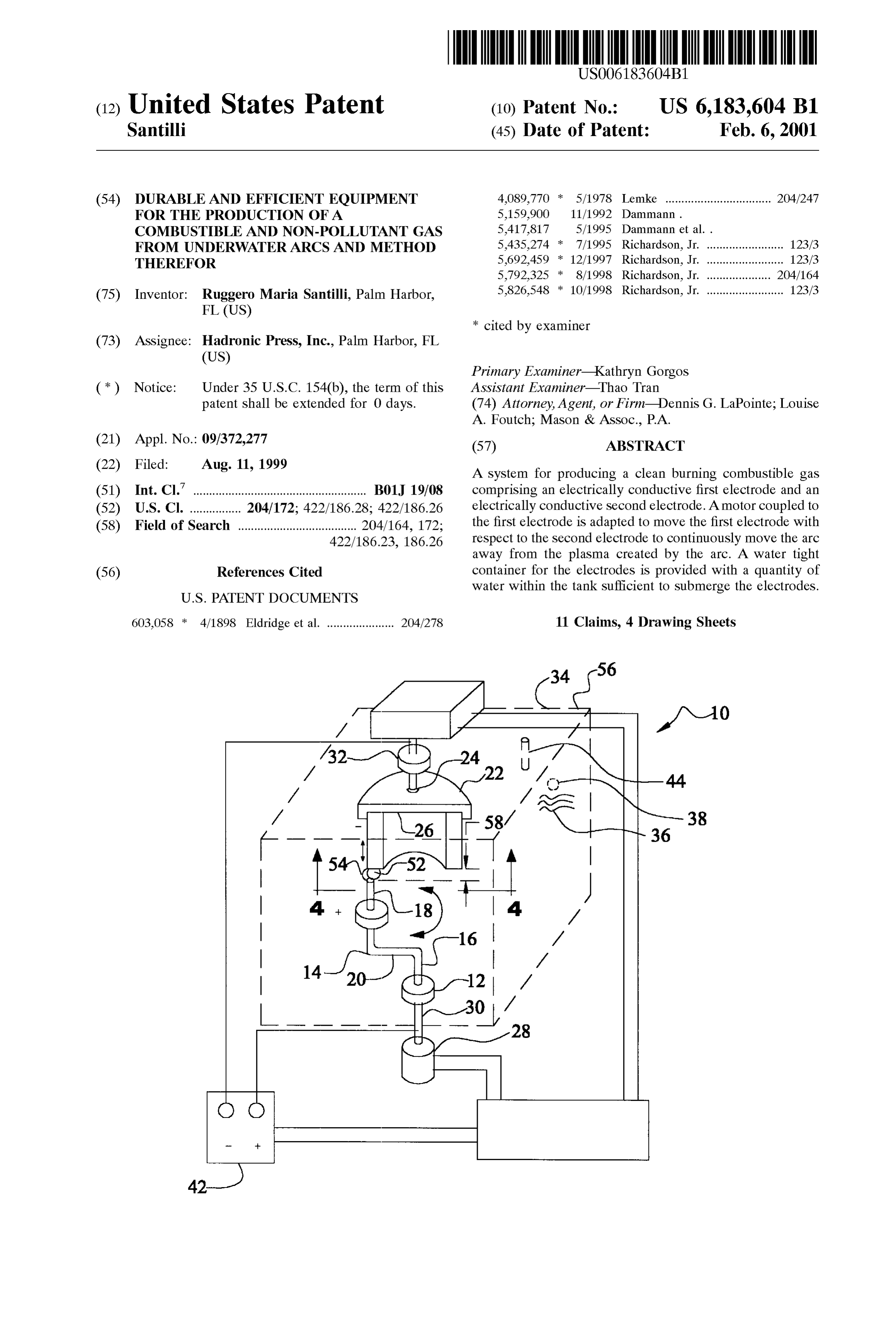
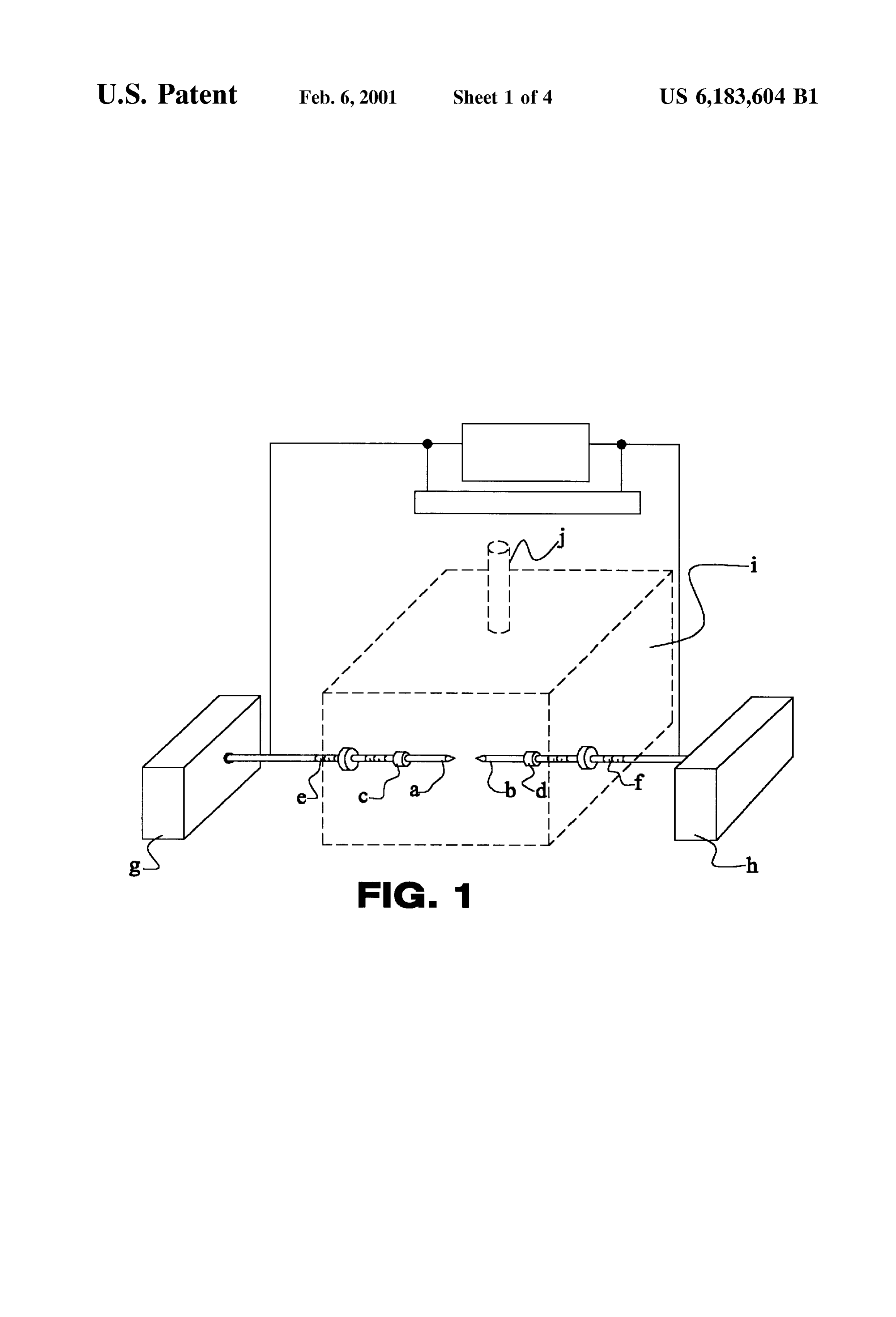
potential to the anode and the cathode while the anode is FIGS. 1 and 2 are illustrations of prior art equipment for rotating and the cathode is shifting axially. the fabrication of a pollutant-free combustible gas produced There has thus been outlined, rather broadly, the more by an electric arc under water constructed with prior art important features of the invention in order that the detailed 60 technique.
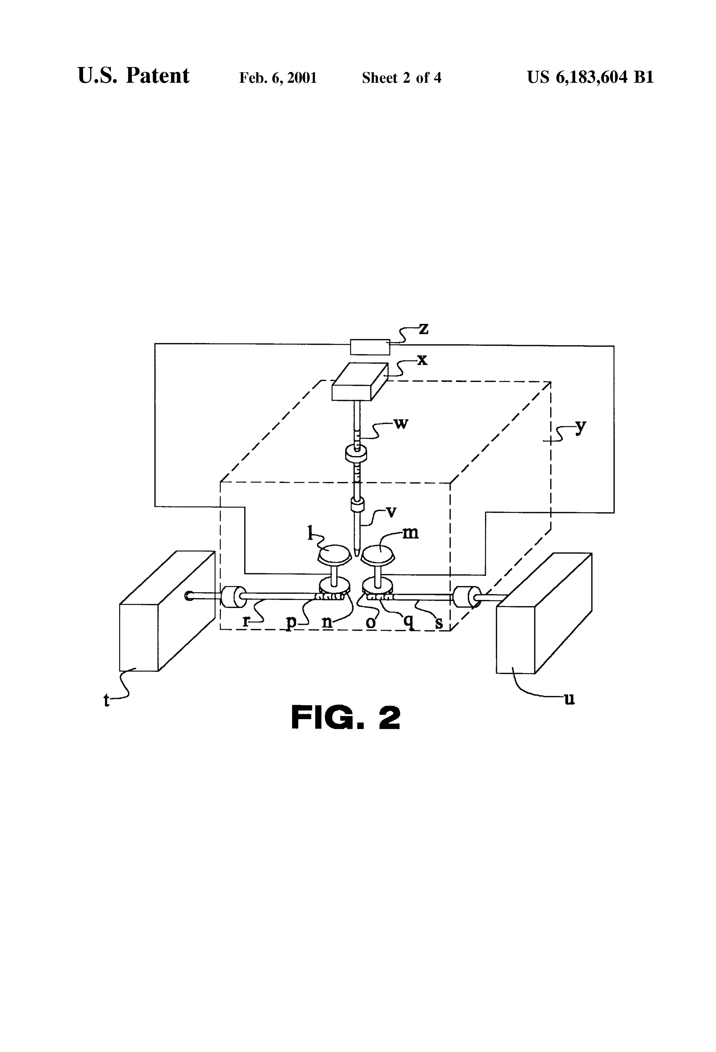
description thereof that follows may be better understood FIG. 3 is a Schematic diagram depicting the principles of and in order that the present contribution to the art may be the present invention.
better appreciated. There are, of course, additional features FIG. 4 is a Schematic diagram of a partial Sectional view of the invention that will be described hereinafter and which taken along line 4-4 of FIG. 3, depicting an additional will form the Subject matter of the claims appended hereto. 65 embodiment of the present invention. In this respect, before explaining at least one embodiment The same reference numerals refer to the same parts of the invention in detail, it is to be understood that the throughout the various Figures.
Page 8
S 6
DESCRIPTION OF THE PREFERRED l, m: carbon disk electrodes
EMBODIMENT n, O: gear rotating 1 & m p, q: Side gear for rotating n & O
With reference to FIG. 1, a typical embodiment of the r, S: Shaft of gears p & q electrodes of current use for the production of a combustible gas from underwater arcs is that in which one or more pairs t, u: mechanism for rotating Shafts r & S of Solid carbon rods are immersed within the selected liquid v: electrodes neutral vertical rod head-on along their cylindrical Symmetry axis. The activa W: advancement of V tion of the arc first requires the physical contact of the tips X: mechanism for advancement of V of the two rods, with consequential large Surge of electricity 1O y: reactor chamber due to shorting, followed by a retraction of the electrodes up Z: electrical power mechanism to the arc gap, which is typically of the order of /16 inch This inventor believes that the primary origin of the depending on power input. The components of Such embodi insufficiency herein considered rests with the carbon rods ment include: themselves, which are indeed effective for underwater
a, b. carbon electrodes welding, but are not adequate for the different Scope of producing a combustible gas from underwater arcs.
c, d: holder of a & b With reference to FIG. 3, this invention specifically deals e., f: Screws for advancement of a & b with an equipment that Solves the insufficiency herein g, h: mechanism for the advancement of a & b considered, by achieving the duration desired by the i: reaction chamber manufacturer, while Sustaining a continuous arc without j: exit of combustible gas from chamber interruptions for the entire desired duration. For the case of Numerous alternatives to the above typical embodiment large industrial production of Said combustible gas with electrical energy input of the order of 100 Kwh, a represen have been invented. For instance, in the U.S. Pat. No.
603,058 (H. Eldridge, 1898) one can see a variety of 25 tative equipment of this invention essentially consists of configurations of the electrodes, including rod shaped 1) One or more arcs produced by a DC current as typically anodes and disk-shaped cathodes. As a further example also available in commercially Sold power units, with reference to FIG. 1, the embodiment of U.S. Pat. No. 2) One or more anodes made of solid rods of about 1 inch 5,159,900 (W. A. Dammann and D. Wallman, 1992) and in diameter and about 2 inches in length and composed U.S. Pat. No. 5,417,817 (W. A. Dammann and D. Wallman, by a high temperature conductor, Such as Tungsten or 1995), essentially consists of the preceding geometric con ceramic. Extensive and diversified experimentations figuration of the electrodes, complemented by a mechanisms have established that the consumption of Said anode for the inversion of polarity between the electrodes, in view composed by ordinary Tungsten is minimal, and defi of the fact that the cathode experiences the highest con nitely of the order of Several weeks of operation. Sumption under a DC arc, while the anode experiences a 35 3) One or more carbon-based cathodes in the configura comparatively much reduced consumption. Even though tion of a large hollow rod geometrically defined as a innovative, this Second embodiment also remains manifestly cylinder with the same thickness of the anode, but with insufficient to achieve the duration of the electrodes needed a radius and length Selected to provide the desired for industrial maturity, while adding other insufficiencies, duration. This cathode performs the vital function of Such as the interruption of the arc at each time the polarities 40 becoming incandescent in the immediate vicinity of the are inverted, with consequential loSS of time and efficiency arc, thus releasing carbon to the plasma. due to the indicated electrical Surges each time the arc is With greater specificity and with reference to FIGS. 3 and initiated. 4, the present invention essentially comprises a new and AS an additional example, and with reference to FIG. 2, improved System 10 for producing a clean burning combus the mechanism of the U.S. Pat. No. 5,792,325 (W. H. 45 tible gas from an electric arc generating plasma under water. Richardson, Jr., 1998), has a different preferred embodiment First provided is an electrically conductive anode 12 fabri consisting of one or more pairs of electrodes in the shape of cated of tungsten. The anode is Solid in a generally cylin carbon disks rotating at a distance along their peripheral drical configuration with a diameter of about one inch and a edges, in between which an electrically neutral carbon rod is length of about three inches.
inserted. Said rod causes the shorting necessary to activate 50 Next provided is a generally Z-shaped crank 14 of a the arc, and then the maintenance of the arc itself. This latter electrically conductive material. The crank has a linear mechanism also does not resolve the main problem herein output end 16 Supporting the anode. The crank also has a considered. In fact, the neutral carbon rod is consumed at linear input end 18 essentially parallel with the output end. essentially the same rate as that of the preceding embodi A transverse connecting portion 20 is located between the ments. In addition, the mechanism has the disadvantage of 55 input and output ends.
breaking down the Single arc between two cylindrical elec An electrically conductive cathode 22 is next provided. trodes into two Separate arcs, one per each the two couplings The cathode is fabricated of carbon. The carbon is in a of the conducting disk and the neutral rod, with consequen hollow tubular configuration with an axis. The cathode has tial reduction of efficiency due to the drop of Voltage and a Supported end 24 and a free end 26. The cathode has a other factors. Numerous means can be envisaged to improve 60 length of about 12 inches and an internal diameter of about the life of carbon electrodes, Such as mechanisms based on 11% inches and an external diameter of about 12% inches. barrel-type rapid replacements of the carbon rods. These A motor 28 is next provided. The motor has a rotatable mechanisms are not preferred here because the arc has to be drive shaft 30. The drive shaft has a fixed axis of rotation. reactivated every time a rod is replaced, thus requiring the The motor is coupled to the input end of the crank and is re-establishing of the arc with physical contact, and conse 65 adapted to rotate the crank to move the output end and anode quential Shortcomings indicated earlier. The components of in a circular path of travel. The circular path of travel has a Such embodiment include: diameter of about twelve inches with the anode located
Page 9
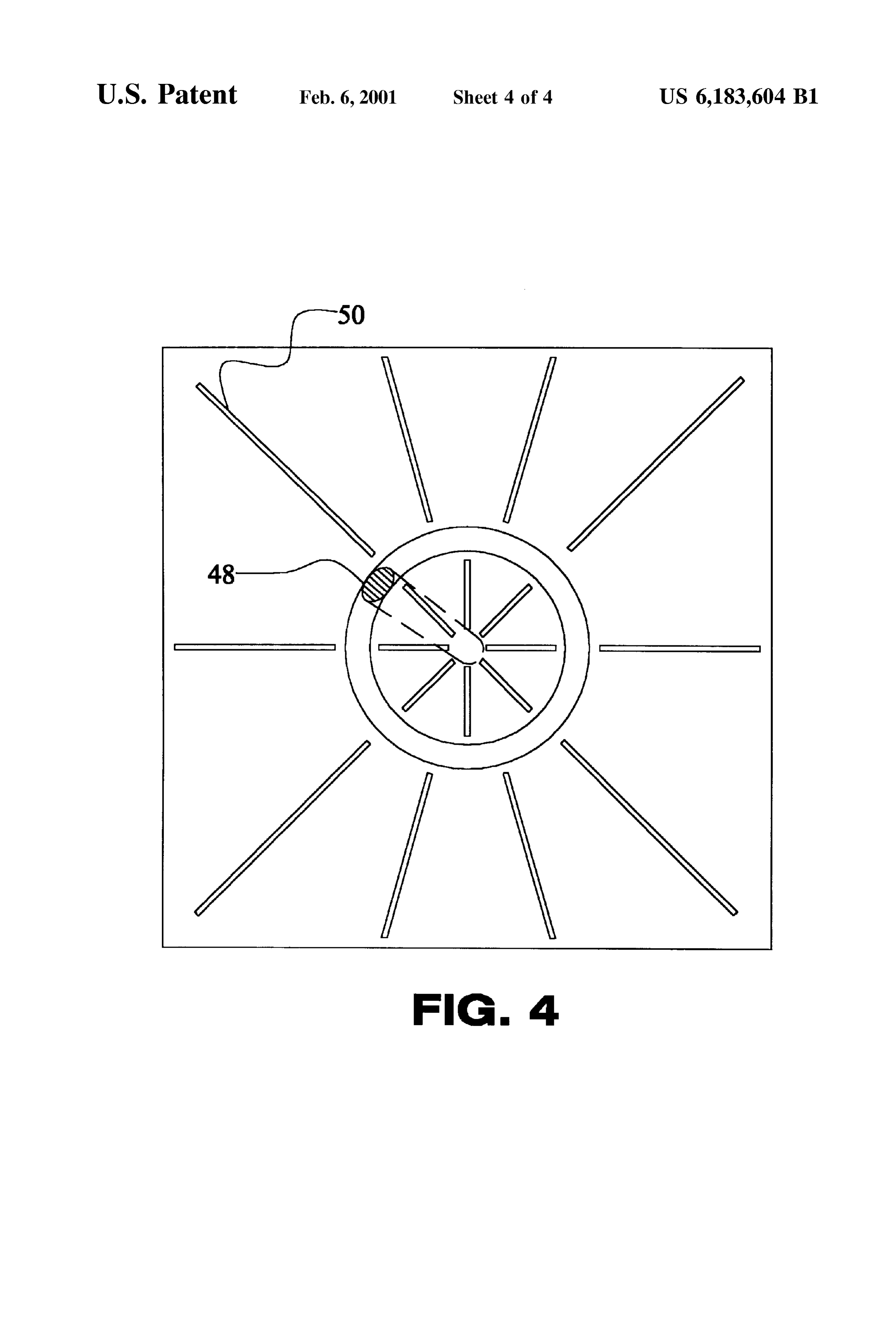
adjacent to the free end of the cathode. In this manner the minute. Numerous experimentations have established that a anode and the arc are continuously moved around the cylindrical carbon cathode of 16 thickness, approximately cathode and away from the plasma created by the arc. one foot radius and approximately two feet length permits Next provided is an axially shifted support 32. The the achievement of the desired duration of 4 hours of Support is in a circular configuration to receive the Supported continuous use prior to Service. In fact, Such a geometry end of the cathode and to move the cathode axially toward implies that each 1 inch Section of the cylindrical cathode is the anode as the carbon of the cathode is consumed during consumed in 6 minutes. Since 4 hours correspond to 240 operation and use. minutes, the duration of four hours of continuous use A water tight container 34 for the anode, cathode, crank requires forty 1 inch Sections of the cylindrical cathode. and Support is next provided. A quantity of water 36 is Then, the desired 4 hours duration of Said cathode requires provided within the tank Sufficient to Submerge the anode the radius R=40/3.14=12.7 inches, as indicated. It is evident and the cathode. that a cylindrical carbon cathode of about two feet in radius An entrance port 38 is provided in the container. The and about one foot in length has essentially the same entrance port functions to feed water and a carbon enriched duration as the preceding configuration of one foot radius fluid into the container to Supplement the carbon and water 15 and two feet length. As a Second example for consumer units lost from the container during operation and use. with Smaller power input than the above, the same duration Next provided is a source of potential 42. The source of of 4 hours prior to Servicing can be reached with propor potential couples the anode and the cathode. In this manner tionately Smaller dimensions of Said electrodes which can be an electrical arc is created between the anode and the easily computed via the above calculations. cathode with a Surrounding plasma for the production of gas It is important to show that the same equipment described within the water. The gas will then bubble upwardly to above above also permits the increase of the efficiency as defined the water. earlier. In-depth Studies conducted by this inventor at the Lastly provided is an exit port 44 for exhausting gas particle, atomic and molecular levels here, omitted for resulting from the application of current from the Source of brevity, have established that the arc is very efficient in potential to the anode and the cathode while the anode is 25 decomposing water molecules into hydrogen and oxygen rotating and the cathode is shifting axially. gases. The low efficiency in the production of a combustible FIG. 4 is a cross-sectional view taken along line 4-4 of gas under the additional presence of carbon as in pre FIG. 3, but is directed to an alternate embodiment. In Such existing patents is due to the fact that, when Said H and O embodiment, the anode 48 is wing shaped to cause leSS gases are formed in the plasma Surrounding the discharge, turbulence in the water when moving. In addition, various most of these gases burn, by returning to form again water supports 50 are provided for abating turbulence and for molecules. In turn, the loSS due to re-creation of water providing rigidity. molecules is the evident main reason for the low efficiency Again with reference to FIG. 3, the anode rod is placed of pre-existing equipment. The Very reason for Said poor head-on on the edge of the cylindrical cathode and is efficiency is the stationary nature of the arc itself within the permitted to rotate around the entire periphery of Said 35 plasma, because under these conditions the arc triggers the cylindrical edge via an electric motor or other means. The combustion of hydrogen and oxygen originally created from inverse case of the rotation of the cathode cylinder on a fixed the Separation of the water.
anode rod or the Simultaneous rotation of both, are equally The above described new equipment of this invention also acceptable, although more expensive for engineering and improves the efficiency. In fact, Said efficiency can be production. Extensive tests have established that, under a 40 improved by removing the arc from the plasma immediately Sufficient rotational Speed of the anode rod on the cylindrical after its formation. In turn, an effective way for achieving cathode of the order of 100 rp.m. or thereabout, the con Such an objective without extinguishing the arc itself is to Sumption of the edge of the cathode tube is uniform, thus keep the liquid and plasma in Stationary conditions, and permitting the desired continuous underwater arc without rapidly move instead the arc away from the plasma. This the interruptions necessary for the frequent cathode rod 45 function is precisely fulfilled by the new equipment of this replacements in the pre-existing configurations. invention because the arc continuously rotates, by therefore For the case of Smaller electrical power input the above exiting the plasma immediately after its formation. Exten equipment remains essentially the same, except for the Sive experimentations conducted have established that the reduction of the diameter of the non-carbon based anode and new equipment of this invention can increase the efficiency of the corresponding thickness of the carbon-based cylin 50 from the 2-3 cf per Kwh of current embodiments to 4-6 cf drical cathode. For instance, for 14 KWh power input, Said per Kwh.
anode diameter and related thickness of the cylindrical It is easy to See that the same equipment of this invention cathode can be reduced to about ys inch. also decreases the content of carbon dioxide. In fact, CO is The above new equipment does indeed permit the formed by burning CO and O, thus originating from a achievement of the desired duration of the electrodes prior 55 Secondary chemical reaction in the arc plasma following the to Servicing. As a first illustration for industrial usage, creation of CO. But the latter reaction is triggered precisely Suppose that the manufacturer desires an equipment for the by the stationary arc within the plasma. Therefore, the high Volume industrial production of Said combustible gas removal of the arc from the plasma after its formation via the from about 100 Kwh energy input with the duration of four fast rotation of the anode on the cylindrical edge of the hours, thus requiring the Servicing twice a day, once for 60 cathode while the liquid is Stationary implies a decrease of lunch break and the other at the end of the working day, as CO content because of the decrease of the ignition of CO compared to the Servicing only after a few minutes of use for and O. Extensive experimentation has established that a the pre-existing equipment. rotation of 100 rp.m of the anode over the edge of the This invention readily permits the achievement of said cylindrical cathode of radius one foot decreases the content duration under Said power input. Recall that carbon rods of 65 of carbon dioxide in the combustible gas at least by half, thus about 16 in diameter are consumed by the underwater arc permitting a significant environmental advance. The from 100 Kwhat the speed of about 3 inches in length per decrease of the CO2 content also implies an increase of the
Page 10
efficiency alternatively defined as energy content of the gas The remote operation of the equipment is essentially as produced per hour (BTUh) divided by the real electric follows:
energy absorbed per hour (Kwh). In fact, CO2 is a non 1) The equipment is Switched on with electric current combustible gas, thus having no meaningful BTU content. It automatically Set at minimum, the anode rod automati is then evident that, Since the total carbon content in the gas cally initiating its rotation on the edge of the cylindrical remains the same, the decrease of the non-combustible CO cathode, and the arc being open; is replaced in the gas by a corresponding increase of the combustible CO with the same carbon content, thus increas 2) The automation decreases the distance between anode ing the energy content of the gas for the same production and cathode until the arc is initiated, while the amps are Volume of pre-existing inventions and for the same real released automatically to the desired value per each power absorbed. given Kwh, and the gap distance is automatically kept With reference to FIG. 3, among various possible to the optimal value of the selected liquid and Kwh via alternatives, a preferred embodiment of this invention for the mechanical and/or optical and/or electrical Sensors, high Volume industrial production of a combustible gas from 3) The above equipment produces the combustible gas underwater arcs with about 100 Kwh real electrical energy 15 under pressure inside the metal vessel, which is then essentially comprises: transferred to the Storage tank via pressure difference or A) An enclosed reactor chamber of the approximate a pump, production of Said combustible gas then con dimensions 4 feet high, 3 feet wide and 3 feet long tinues automatically until the complete consumption of fabricated out of steel sheets or other metal of about 4 Said cylindrical carbon cathode inch thickness, comprising in its interior the electrodes AS to the manner of usage and operation of the present for the creation of the arc Serviced by Said power input invention, the same should be apparent from the above and having means for the exiting of the gas produced in description. Accordingly, no further discussion relating to its interior as well as means for the rapid access or the manner of usage and operation will be provided. servicing 56 of the internal electrodes for services; With respect to the above description then, it is to be B) The filling up of said chamber with a liquid generally 25 realized that the optimum dimensional relationships for the consisting of water and/or water Saturated with carbon parts of the invention, to include variations in size, materials, rich water Soluble Substances, shape, form, function and manner of operation, assembly C) One or more anodes consisting of rods of about 1 inch and use, are deemed readily apparent and obvious to one diameter and about 2 inches length made of Tungsten skilled in the art, and all equivalent relationships to those or other temperature resistant conductor; illustrated in the drawings and described in the Specification D) One or more cylindrical shaped carbon cathodes with are intended to be encompassed by the present invention. essentially the Same thickness as that of the anodes and Therefore, the foregoing is considered as illustrative only with radius and length Selected for the desired duration; of the principles of the invention. Further, Since numerous E) Electromechanical means for the rotation of the anode modifications and changes will readily occur to those skilled rod head-wise on the edge of the cylindrical cathode, or 35 in the art, it is not desired to limit the invention to the exact the rotation of the edge of the cylindrical cathode on a construction and operation shown and described, and Stationary anode rod, or the Simultaneous rotation of accordingly, all Suitable modifications and equivalents may both; be resorted to, falling within the Scope of the invention. F) Automation for the initiation of the arc and its main byWhat is claimed as being new and desired to be protected Letters Patent of the United States is as follows:
tenance via the automatic advancement of the carbon 40 cathode, and/or the anode rod and/or both, in Such a 1. Apparatus for the production of a combustible and way to maintain constant the arc gap 58. non-polluting gas from Submerged arcs between electrodes comprising:
G) Fastenings of said cylindrical carbon cathode Such to an electrical DC power Supply Suitable to generate an permit its rapid replacement; various gauges for the remote monitoring of the power unit, combustible gas, 45 underwater arc between electrodes, liquid and electrodes, tank for the Storage of the gas an enclosed pressure resistant reactor chamber, the cham produced and miscellaneous other items. ber having means for the exiting of a produced com An improved version of the above embodiment is con bustible gas, the chamber further having means for the ceived to minimize the rotation of Said liquid because of rapid Servicing of the electrodes, the electrodes being drag due to the Submerged rotation of the anode, with 50 inside Said chamber;
consequential return to the Stationary character of the plasma a liquid filling up Said reactor chamber at least to Sub 54 and the arc, consequential loSS of efficiency and increase merge Said electrodes, and of CO content for the reasons indicated above. the electrodes including a rod-shaped anode made from an With reference to FIG. 4, and among a variety of extended life temperature resistant conductor, means embodiments, this objective can be achieved by Shaping the 55 for rotating Said anode head-wise on an edge of a rotating anode in the form of a wing with minimal possible cylindrical-shaped carbon cathode having essentially drag resistance while rotating within Said liquid, and by the same thickness as the anode, the cathode having a inserting in the interior of the enclosed reactor chamber predetermined radius and length corresponding to a panels fabricated out of metal or other Strong material with desired operational duration, the cathode further having the approximate thickness of /s inch, Said panels being 60 means for providing a forward and backward motion placed not in contact with yet close to the cathode and the for maintaining a gap distance between the anode and anode in a radially distributed with respect to the cylindrical cathode after initiation of the generated arc, Symmetry axis of the equipment and placed both inside as wherein the generated arc acroSS the electrodes Sub well as outside Said cylindrical cathode. The latter panels merged in the liquid produces a combustible and non perform the evident function of minimizing the rotational 65 pollutant gas.
motion of Said liquid due to drag created by the Submerged 2. The apparatus according to claim 1, wherein the DC rotation of the anode. power Supply further includes means for automation for the
Page 11
initiation of the generated arc between Said anode and an exit port for exhausting gas resulting from the appli cathode, the DC power Supply also being in electrical cation of current from the Source of potential to the communication with the means for providing the forward anode and the cathode while the anode is rotating and and backward motion of the cathode.
3. The apparatus according to claim 1, wherein Said the cathode is shifting axially. rod-shaped anode is wing shaped for minimizing a resis 6. A System for producing a clean burning combustible tance while rotating within Said liquid, Said reactor chamber gas comprising:
additionally having radially oriented panels for reducing a an electrically conductive first electrode, rotation of Said liquid caused by the Submerged rotation of a generally Z-shaped crank of an electrically conductive the anode.
4. The apparatus according to claim 1 further comprising material Supporting the first electrode, a water Soluble carbon rich Substance added to the liquid. an electrically conductive Second electrode, 5. A new and improved System for producing a clean a motor coupled to the first electrode and Supporting burning combustible gas from an electric arc generating Z-shaped crank and adapted to move the first electrode plasma under water comprising, in combination: 15 with respect to the Second electrode to continuously an electrically conductive anode fabricated of tungsten, move an arc generated between the first and Second the anode being Solid in a generally cylindrical con electrodes away from a plasma created by the arc, and figuration;
a generally Z-shaped crank of an electrically conductive a water tight tank within which is disposed the electrodes material having a linear output end Supporting the with a quantity of water within the tank sufficient to anode and a linear input end essentially parallel with Submerge the electrodes.
the output end and with a transverse connecting portion 7. The system as set forth in claim 5 wherein the cathode therebetween; is fabricated of graphite in the form of an enlarged hollow an electrically conductive cathode fabricated of carbon, cylinder.
the carbon cathode being in a hollow tubular configu 8. The system as set forth in claim 6 wherein the first ration with an axis, Said cathode having a Supported end 25 electrode is an anode made from a non-consumable electri and a free end; cally conductive material.
a motor with a rotatable drive shaft having a fixed axis of 9. The system as set forth in claim 8, wherein the rotation aligned with the axis of the cathode and non-consumable electrically conductive material is one of coupled to the input end of the Z-shaped crank and tungsten, tungsten alloy, ceramic, and combinations thereof. adapted to rotate the Z-shaped crank to move the output 10. A method for producing a clean burning combustible end and anode in a circular path of travel with the anode gas comprising the Steps of:
located adjacent to the free end of the cathode to continuously move the anode around the cathode Such providing an electrically conductive first electrode, that an arc is moving away from a plasma created by providing a generally Z-shaped crank of an electrically the arc to form additional plasmas around a periphery 35 conductive material Supporting the first electrode, of the cathode; providing an electrically conductive Second electrode of an axially shifted Support in a circular configuration to an essentially non-combustible material in a Solid receive the Supported end of the cathode and to move cylindrical configuration;
the cathode axially toward the anode as the carbon of 40 disposing the electrodes in a preSSure tight tank filled with the cathode is consumed during operation and use; a quantity of liquid within the tank Sufficient to Sub a pressure tight tank within which is disposed the anode, merge the electrodes, the electrodes for generating an cathode, crank and Support with a quantity of water arc to produce a combustible gas when electrical cur within the tank Sufficient to Submerge the anode and the rent is applied to the electrodes, and
an entrance port in the tank to feed the quantity of water moving the first electrode with respect to the Second and a carbon enriched fluid into the tank to Supplement electrode to continuously move the arc away from a the carbon and water lost from the tank during opera plasma created by the arc.
tion and use; 11. The method for producing a clean burning combus a Source of potential coupling the anode and the cathode 50 tible gas according to claim 8, wherein the non-combustible for the creation of an electrical arc therebetween with material from which the Second electrode is made is tung a Surrounding plasma for the production of gas within Sten.
the water and bubbling upwardly to above the water;
and
Provenance
- Collection
- Cited prior art
- Original PDF
- patentimages.storage.googleapis.com →
- Filed
- 1999-08-11
- Pages
- 11
- Method
- pdftotext (the PDF's own text layer) + pdftoppm 300dpi page scans
- Source
- Google Patents bibliographic record
- Granted
- 2001-02-06
- Inventors
- Ruggero Maria Santilli; Hadronic Press Inc
- Transcribed from
- patentimages.storage.googleapis.com →