patent · US4702600
Method and apparatus for measuring angular rate with a passive optical resonator
27 October 1987
Page 1 — bibliographic record
United States Patent (19) 11 Patent Number: 4,702,600 Handrich et al. (45) Date of Patent: Oct. 27, 1987 54 METHOD AND APPARATUS FOR 4,573,795 3/1986 Auch et al. ......................... 356/350
MEASURING ANGULAR RATE WITH A
PASSIVE OPTICAL RESONATOR Primary Examiner-Vincent P. McGraw
Assistant Examiner-S. A. Turner 75) Inventors: Eberhard Handrich, Kirchzarten; Attorney, Agent, or Firm-Elliott N. Kramsky Werner Schröder, Umkirch, both of 57 ABSTRACT
Fed. Rep. of Germany 73) Assignee: Litef GmbH, Freiburg im Breisgau, A method and apparatus for reading out angular rates Fed. Rep. of Germany by means of a passive optical resonator provides for the generation of three component light beams individually (21) Appl. No.: 757,276 tuned to distinct resonator modes. One component light 22 Filed: Jul. 19, 1985 beam is radiated into the resonator in the opposite direc (30) Foreign Application Priority Data tion to the two other component light beams. By means of an evaluating logic, differences are formed between
Jul. 20, 1984 DE Fed. Rep. of Germany ....... 3426868 the counterrotating light beams and the differences 51) Int. Cl.......................... G01C 19/64; G01B 9/02 weighted and subtracted from each other to provide 52 U.S. Cl. .................................................... 356/350 angular rate. The optical length of the resonator, and, 58) Field of Search ......................................... 356/350 thus, temperature are available as a weighted sum of the differences. Temperature drift may be eliminated from 56) References Cited angular rate measurements by compensation according
4,514,088 4/1985 Coccoli............................... 356/350 4,569,593 2/1986 Auch et al. ......................... 356/350 19 Claims, 4 Drawing Figures
Page 2
Drawing sheet — no readable text.
Page 3
Drawing sheet — no readable text.
Page 4
Drawing sheet — no readable text.
Page 5
Drawing sheet — no readable text.
Page 6
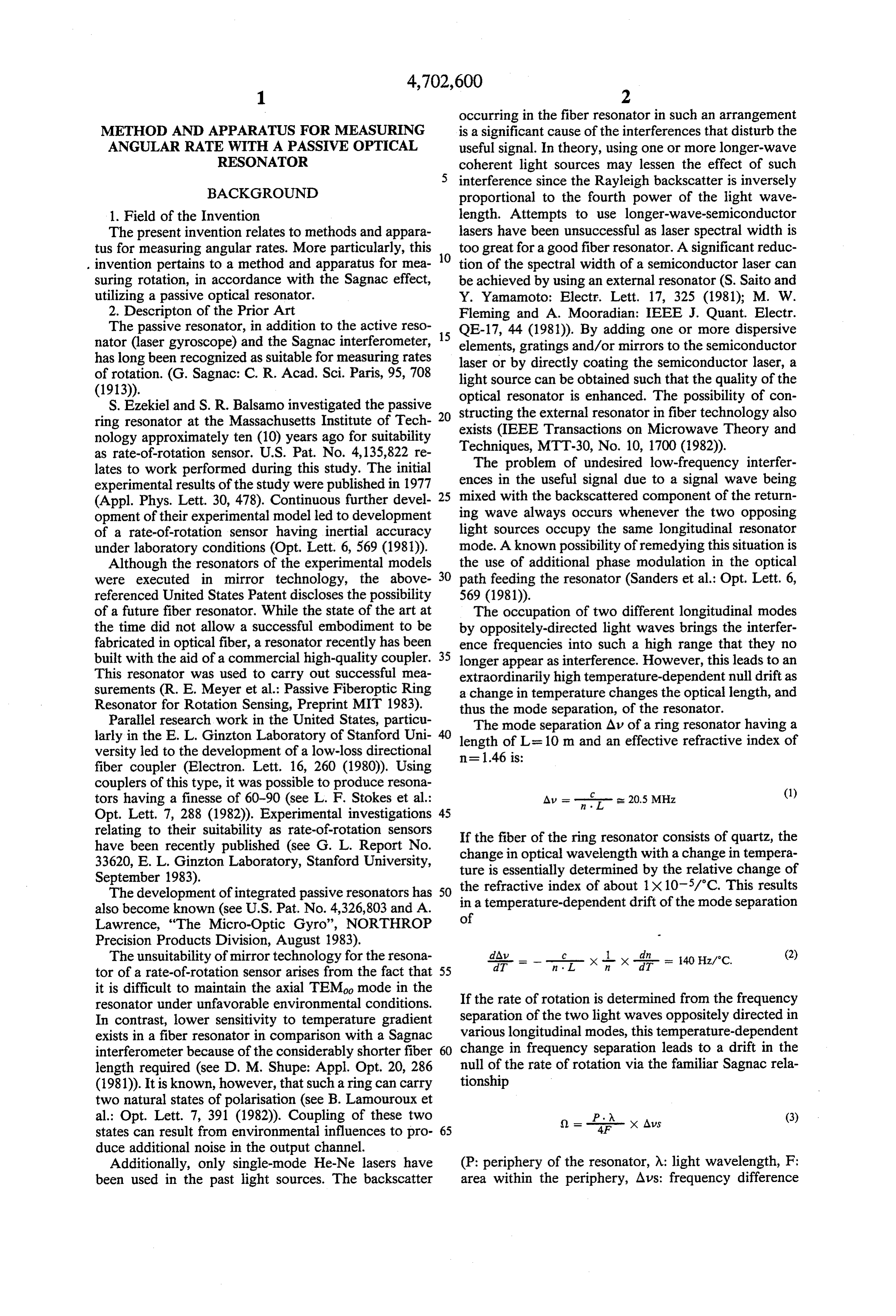
occurring in the fiber resonator in such an arrangement
METHOD AND APPARATUS FOR MEASURING is a significant cause of the interferences that disturb the ANGULAR RATE WITH A PASSIVE OPTICAL useful signal. In theory, using one or more longer-wave RESONATOR coherent light sources may lessen the effect of such interference since the Rayleigh backscatter is inversely
BACKGROUND proportional to the fourth power of the light wave 1. Field of the Invention length. Attempts to use longer-wave-semiconductor The present invention relates to methods and appara lasers have been unsuccessful as laser spectral width is tus for measuring angular rates. More particularly, this too great for a good fiber resonator. A significant reduc . invention pertains to a method and apparatus for mea 10 tion of the spectral width of a semiconductor laser can suring rotation, in accordance with the Sagnac effect, be achieved by using an external resonator (S. Saito and utilizing a passive optical resonator. Y. Yamamoto: Electr. Lett. 17, 325 (1981); M. W. 2. Descripton of the Prior Art Fleming and A. Mooradian: IEEE J. Quant. Electr. The passive resonator, in addition to the active reso 15 QE-17, 44 (1981)). By adding one or more dispersive nator (laser gyroscope) and the Sagnac interferometer, elements, gratings and/or mirrors to the semiconductor has long been recognized as suitable for measuring rates laser or by directly coating the semiconductor laser, a of rotation. (G. Sagnac: C. R. Acad. Sci. Paris, 95, 708 light source can be obtained such that the quality of the
S. Ezekiel and S. R. Balsamo investigated the passive optical structing resonator is enhanced. The possibility of con the external resonator in fiber technology also ring resonator at the Massachusetts Institute of Tech exists (IEEE Transactions on Microwave Theory and nology approximately ten (10) years ago for suitability as rate-of-rotation sensor. U.S. Pat. No. 4,135,822 re Techniques, MTT-30, No. 10, 1700 (1982)). lates to work performed during this study. The initial The problem of undesired low-frequency interfer experimental results of the study were published in 1977 ences in the useful signal due to a signal wave being (Appl. Phys. Lett. 30, 478). Continuous further devel 25 mixed with the backscattered component of the return opment of their experimental model led to development ing wave always occurs whenever the two opposing of a rate-of-rotation sensor having inertial accuracy light sources occupy the same longitudinal resonator under laboratory conditions (Opt. Lett. 6, 569 (1981)). mode. A known possibility of remedying this situation is Although the resonators of the experimental models the use of additional phase modulation in the optical were executed in mirror technology, the above 30 path feeding the resonator (Sanders et al.: Opt. Lett. 6, referenced United States Patent discloses the possibility 569 (1981)).
of a future fiber resonator. While the state of the art at The occupation of two different longitudinal modes the time did not allow a successful embodiment to be by oppositely-directed light waves brings the interfer fabricated in optical fiber, a resonator recently has been ence frequencies into such a high range that they no built with the aid of a commercial high-quality coupler. 35 longer appear as interference. However, this leads to an This resonator was used to carry out successful mea extraordinarily high temperature-dependent null drift as surements (R. E. Meyer et al.: Passive Fiberoptic Ring a change in temperature changes the optical length, and Resonator for Rotation Sensing, Preprint MIT 1983). thus the mode separation, of the resonator. Parallel research work in the United States, particu The mode separation Alv of a ring resonator having a larly in the E. L. Ginzton Laboratory of Stanford Uni length of Lisa 10 m and an effective refractive index of
versity led to the development of a low-loss directional n=1.46 is:
fiber coupler (Electron. Lett. 16, 260 (1980)). Using couplers of this type, it was possible to produce resona tors having a finesse of 60-90 (see L. F. Stokes et al.: Av = n . L- - 20.5 MHz (1) Opt. Lett. 7, 288 (1982). Experimental investigations 45 relating to their suitability as rate-of-rotation sensors If the fiber of the ring resonator consists of quartz, the have been recently published (see G. L. Report No. change in optical wavelength with a change in tempera 33620, E. L. Ginzton Laboratory, Stanford University, ture is essentially determined by the relative change of September 1983).
The development of integrated passive resonators has 50 the refractive index of about 1X 10.5/C. This results in a temperature-dependent drift of the mode separation also become known (see U.S. Pat. No. 4,326,803 and A. of
Lawrence, "The Micro-Optic Gyro', NORTHROP
Precision Products Division, August 1983).
The unsuitability of mirror technology for the resona dAdT =- .
tor of a rate-of-rotation sensor arises from the fact that 55 it is difficult to maintain the axial TEM mode in the resonator under unfavorable environmental conditions. If the rate of rotation is determined from the frequency In contrast, lower sensitivity to temperature gradient separation of the two light waves oppositely directed in exists in a fiber resonator in comparison with a Sagnac various longitudinal modes, this temperature-dependent interferometer because of the considerably shorter fiber 60 change in frequency separation leads to a drift in the length required (see D. M. Shupe: Appl. Opt. 20, 286 null of the rate of rotation via the familiar Sagnac rela (1981). It is known, however, that such a ring can carry tionship two natural states of polarisation (see B. Lamouroux et al.: Opt. Lett. 7, 391 (1982)). Coupling of these two )= X Aus (3) states can result from environmental influences to pro 65 duce additional noise in the output channel.
Additionally, only single-mode He-Ne lasers have (P: periphery of the resonator, X: light wavelength, F: been used in the past light sources. The backscatter area within the periphery, Aus: frequency difference
Page 7
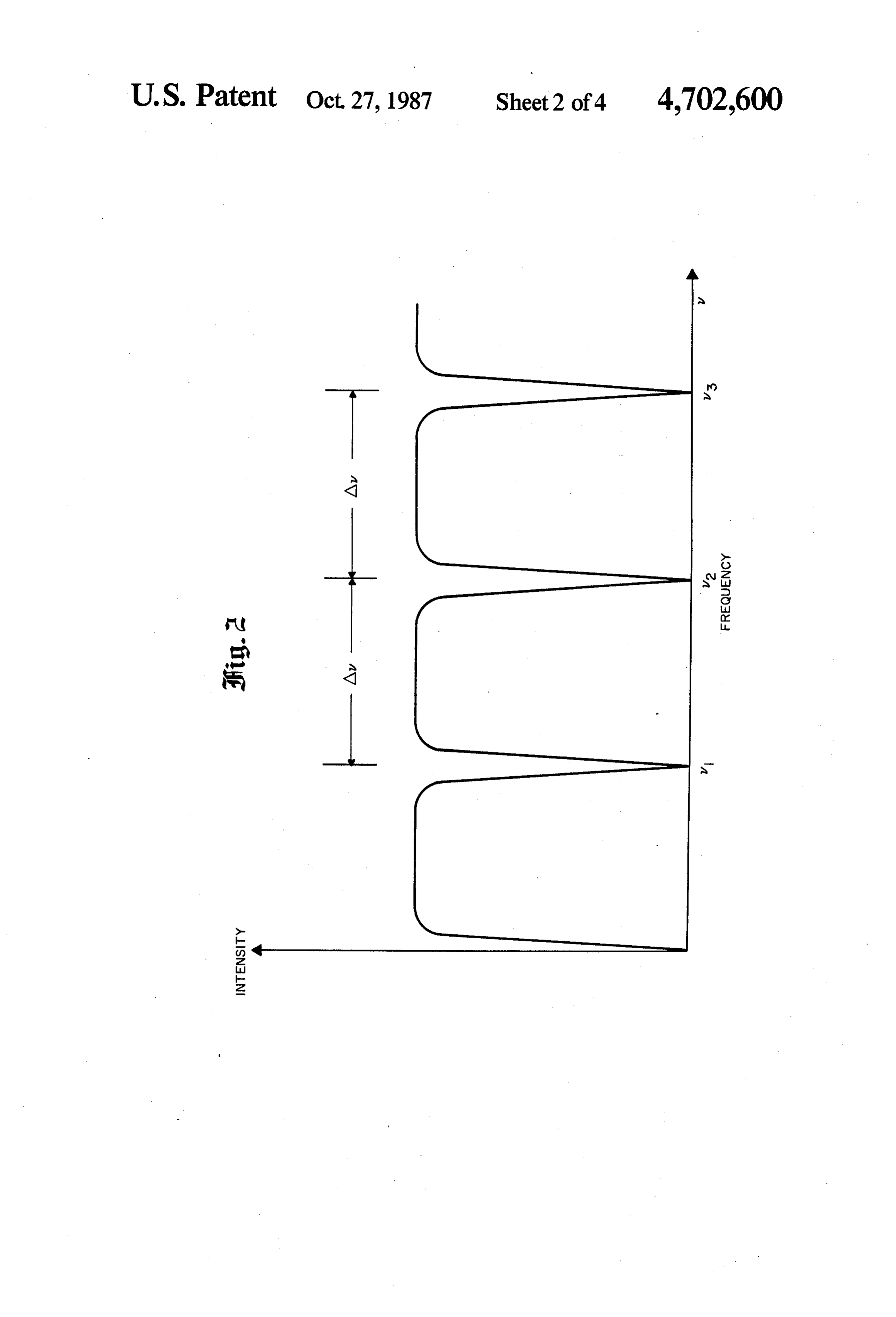
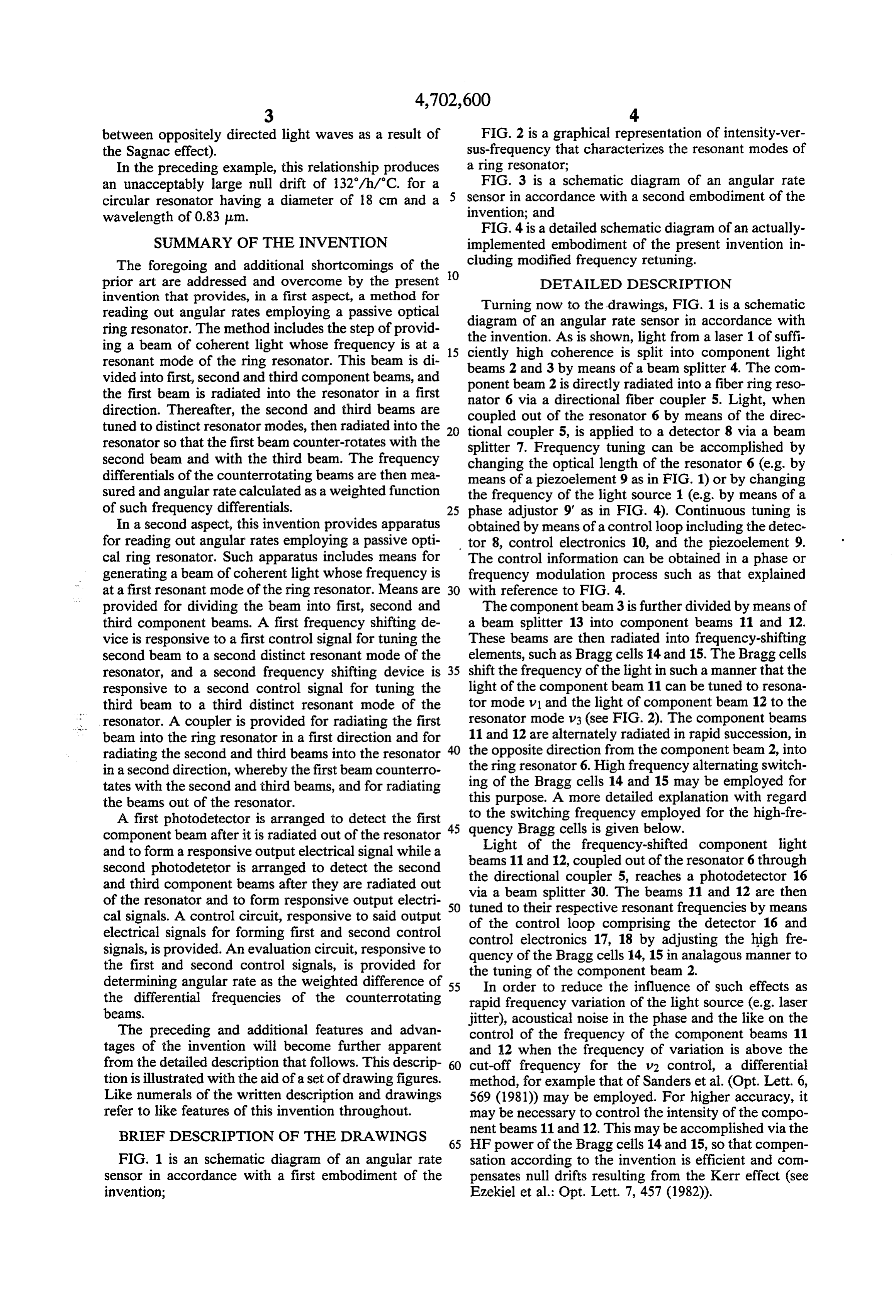
between oppositely directed light waves as a result of FIG. 2 is a graphical representation of intensity-ver the Sagnac effect). sus-frequency that characterizes the resonant modes of In the preceding example, this relationship produces a ring resonator;
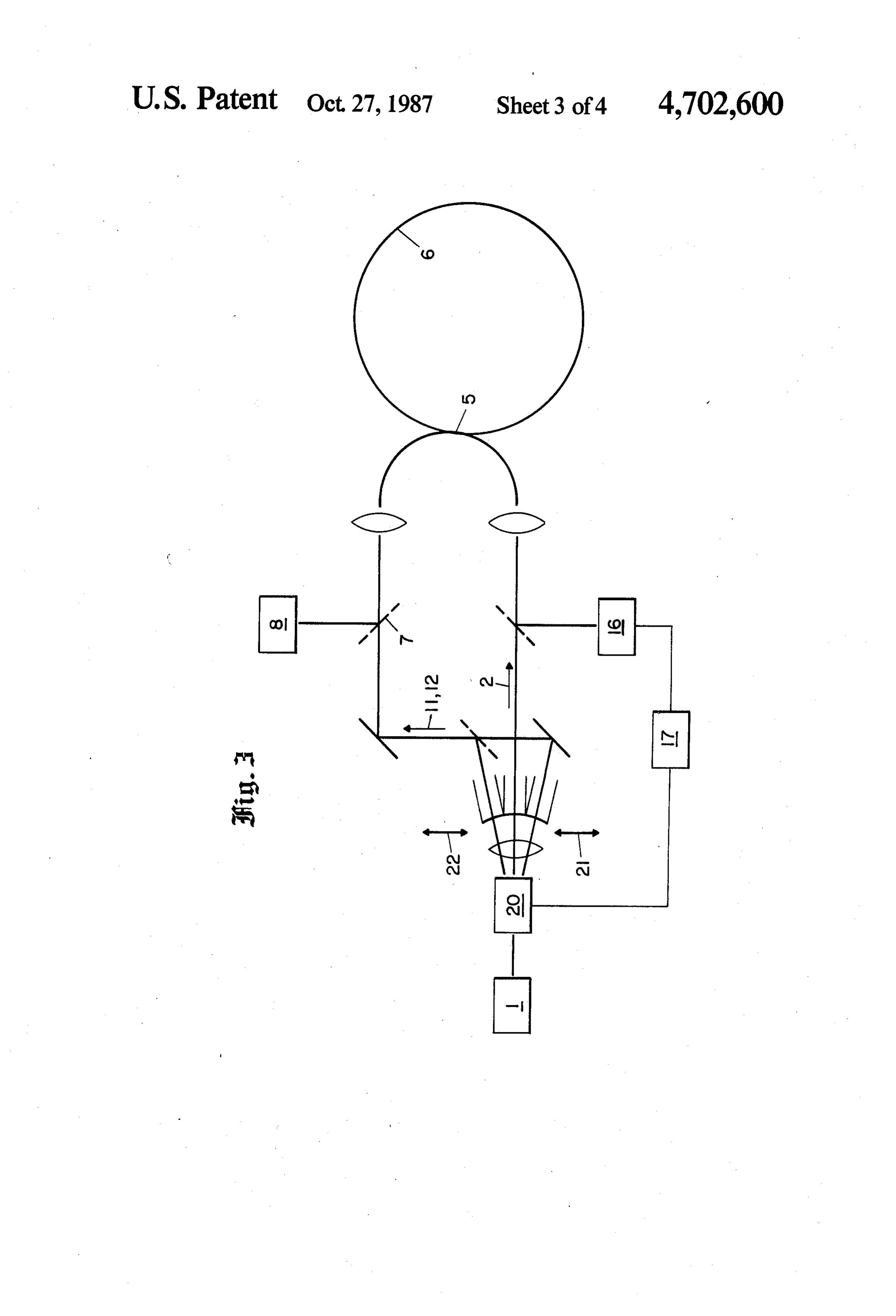
an unacceptably large null drift of 132/h/.C. for a FIG. 3 is a schematic diagram of an angular rate circular resonator having a diameter of 18 cm and a sensor in accordance with a second embodiment of the wavelength of 0.83 um. invention; and
FIG. 4 is a detailed schematic diagram of an actually
SUMMARY OF THE INVENTION implemented embodiment of the present invention in The foregoing and additional shortcomings of the cluding modified frequency retuning.
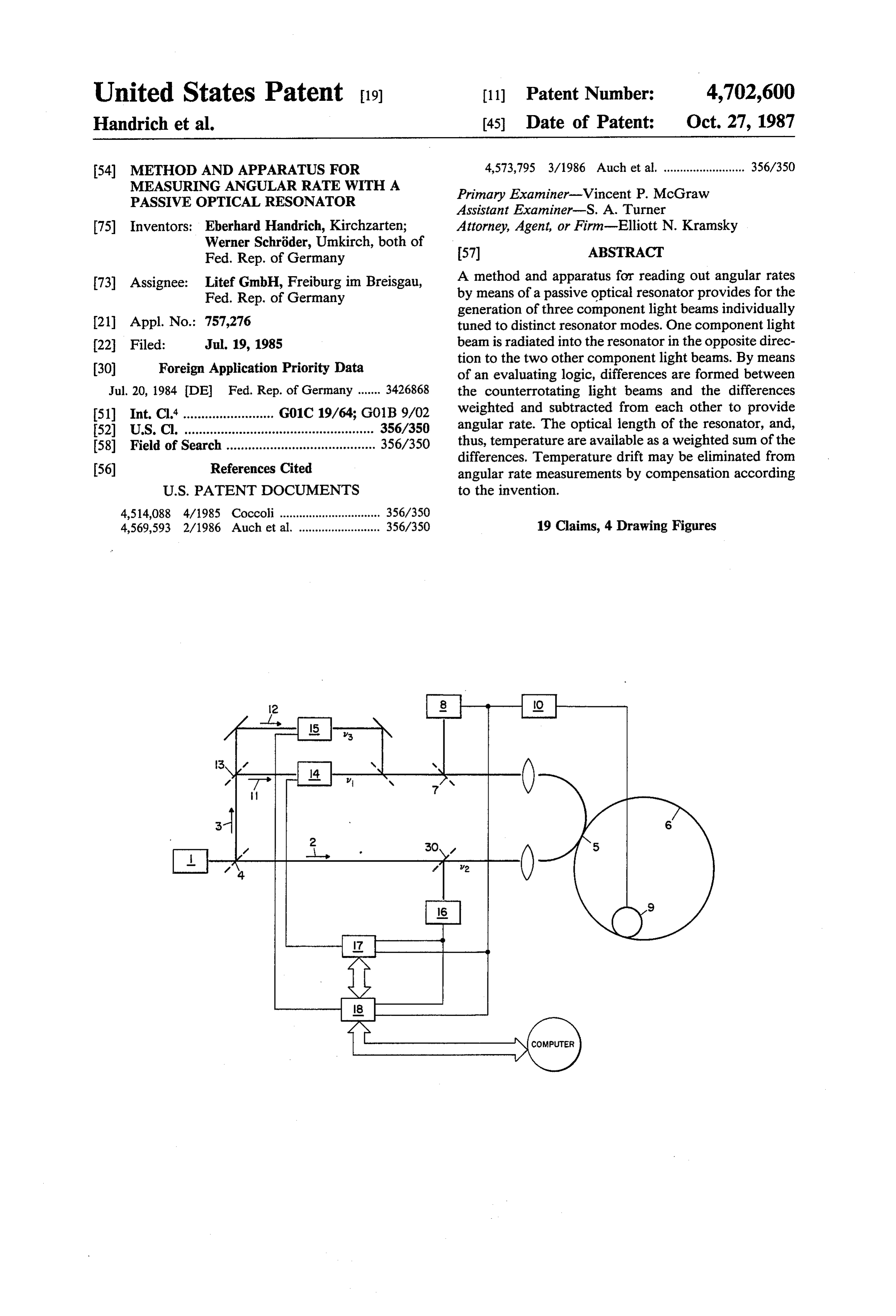
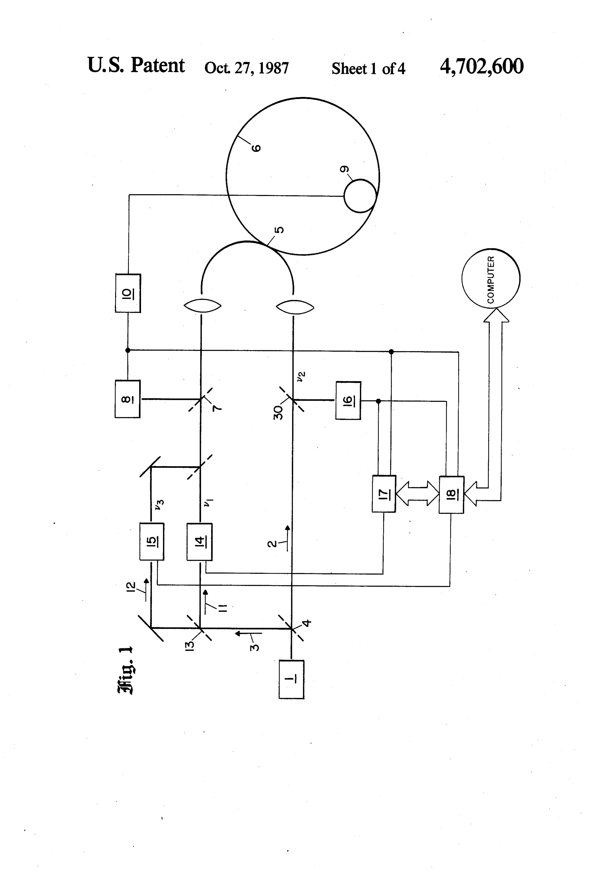
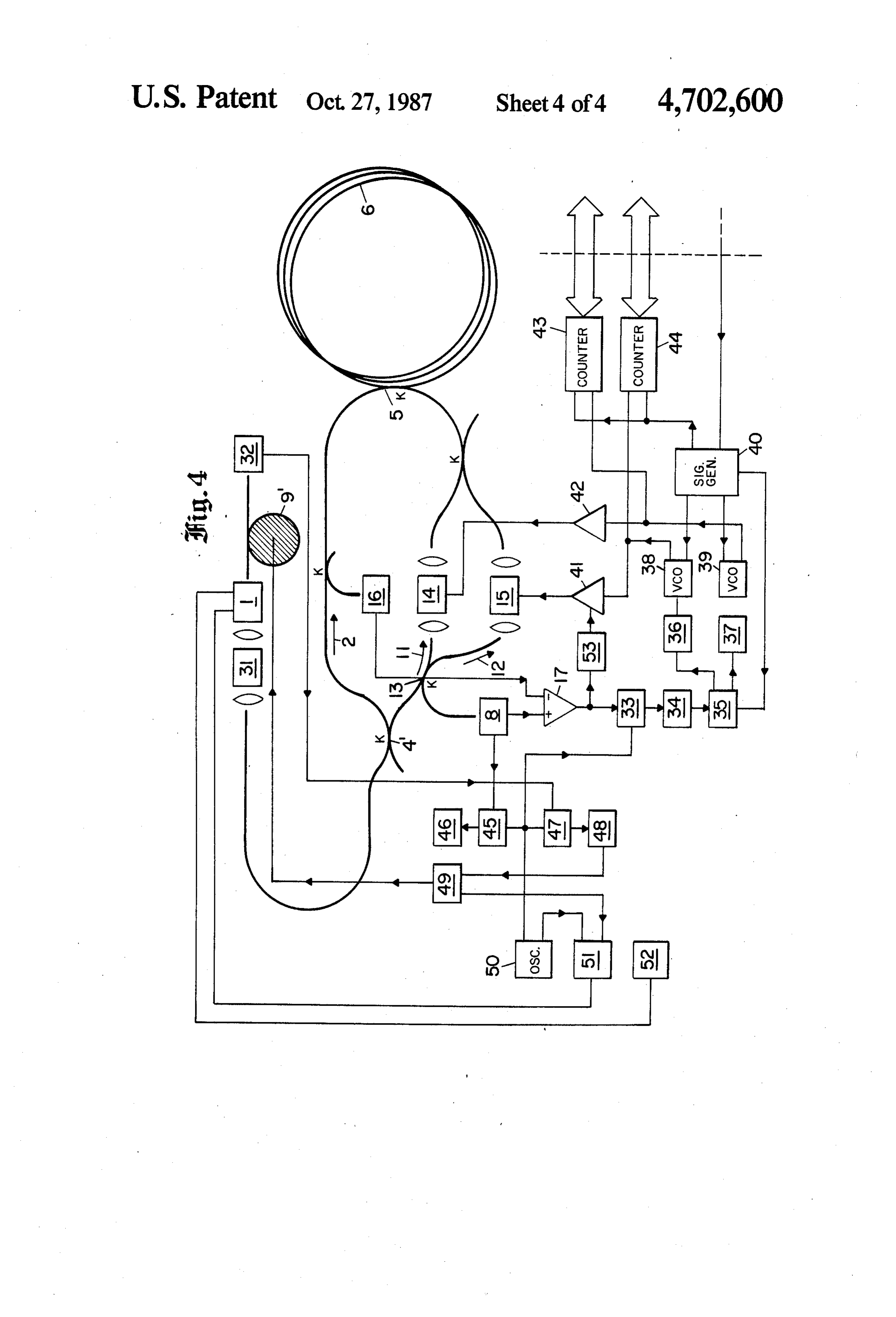
prior art are addressed and overcome by the present O DETALED DESCRIPTION invention that provides, in a first aspect, a method for Turning now to the drawings, FIG. 1 is a schematic reading out angular rates employing a passive optical diagram of an angular rate sensor in accordance with ring resonator. The method includes the step of provid ing a beam of coherent light whose frequency is at a 15 the invention. As is shown, light from a laser 1 of suffi ciently high coherence is split into component light resonant mode of the ring resonator. This beam is di vided into first, second and third component beams, and beams 2 and 3 by means of a beam splitter 4. The com ponent beam 2 is directly radiated into a fiber ring reso the first beam is radiated into the resonator in a first nator 6 via a directional fiber coupler 5. Light, when direction. Thereafter, the second and third beams are coupled out of the resonator 6 by means of the direc tuned to distinct resonator modes, then radiated into the 20 tional coupler 5, is applied to a detector 8 via a beam resonator so that the first beam counter-rotates with the splitter 7. Frequency tuning can be accomplished by second beam and with the third beam. The frequency changing the optical length of the resonator 6 (e.g. by differentials of the counterrotating beams are then mea means of a piezoelement 9 as in FIG. 1) or by changing sured and angular rate calculated as a weighted function the frequency of the light source 1 (e.g. by means of a of such frequency differentials. 25 phase adjustor 9' as in FIG. 4). Continuous tuning is In a second aspect, this invention provides apparatus obtained by means of a control loop including the detec for reading out angular rates employing a passive opti tor 8, control electronics 10, and the piezoelement 9. cal ring resonator. Such apparatus includes means for The control information can be obtained in a phase or generating a beam of coherent light whose frequency is frequency modulation process such as that explained at a first resonant mode of the ring resonator. Means are 30 with reference to FIG. 4.
provided for dividing the beam into first, second and The component beam 3 is further divided by means of third component beams. A first frequency shifting de a beam splitter 13 into component beams 11 and 12. vice is responsive to a first control signal for tuning the These beams are then radiated into frequency-shifting second beam to a second distinct resonant mode of the elements, such as Bragg cells 14 and 15. The Bragg cells resonator, and a second frequency shifting device is 35 shift the frequency of the light in such a manner that the responsive to a second control signal for tuning the light of the component beam 11 can be tuned to resona third beam to a third distinct resonant mode of the tor mode v1 and the light of component beam 12 to the resonator. A coupler is provided for radiating the first resonator mode v3 (see FIG. 2). The component beams beam into the ring resonator in a first direction and for 11 and 12 are alternately radiated in rapid succession, in radiating the second and third beams into the resonator the opposite direction from the component beam 2, into in a second direction, whereby the first beam counterro the ring resonator 6. High frequency alternating switch tates with the second and third beams, and for radiating this ing of the Bragg cells 14 and 15 may be employed for the beams out of the resonator. purpose. A more detailed explanation with regard A first photodetector is arranged to detect the first to the switching frequency employed for the high-fre component beam after it is radiated out of the resonator 45 quency
Light
Bragg cells is given below.
of the frequency-shifted component light and to form a responsive output electrical signal while a second photodetetor is arranged to detect the second beams 11 and 12, coupled out of the resonator 6 through the directional coupler 5, reaches a photodetector 16 and third component beams after they are radiated out via of the resonator and to form responsive output electri 50 tuneda beam splitter 30. The beams 11 and 12 are then cal signals. A control circuit, responsive to said output of the controlrespective to their loop resonant frequencies by means comprising the detector 16 and electrical signals for forming first and second control control electronics 17, 18 by adjusting the high fre signals, is provided. An evaluation circuit, responsive to quency of the Bragg cells 14, 15 in analagous manner to the first and second control signals, is provided for the tuning of the component beam 2.
determining angular rate as the weighted difference of 55 In order to reduce the influence of such effects as the differential frequencies of the counterrotating rapid frequency variation of the light source (e.g. laser beams. jitter), acoustical noise in the phase and the like on the The preceding and additional features and advan control of the frequency of the component beams 11 tages of the invention will become further apparent and 12 when the frequency of variation is above the from the detailed description that follows. This descrip 60 cut-off frequency for the v2 control, a differential tion is illustrated with the aid of a set of drawing figures. method, for example that of Sanders et al. (Opt. Lett. 6, Like numerals of the written description and drawings 569 (1981)) may be employed. For higher accuracy, it refer to like features of this invention throughout. may be necessary to control the intensity of the compo BRIEF DESCRIPTION OF THE DRAWINGS 65 nent beams 11 and 12. This may be accomplished via the HF power of the Bragg cells 14 and 15, so that compen
FIG. 1 is an schematic diagram of an angular rate sation according to the invention is efficient and con sensor in accordance with a first embodiment of the pensates null drifts resulting from the Kerr effect (see invention; Ezekiel et al.: Opt. Lett. 7, 457 (1982)).
Page 8
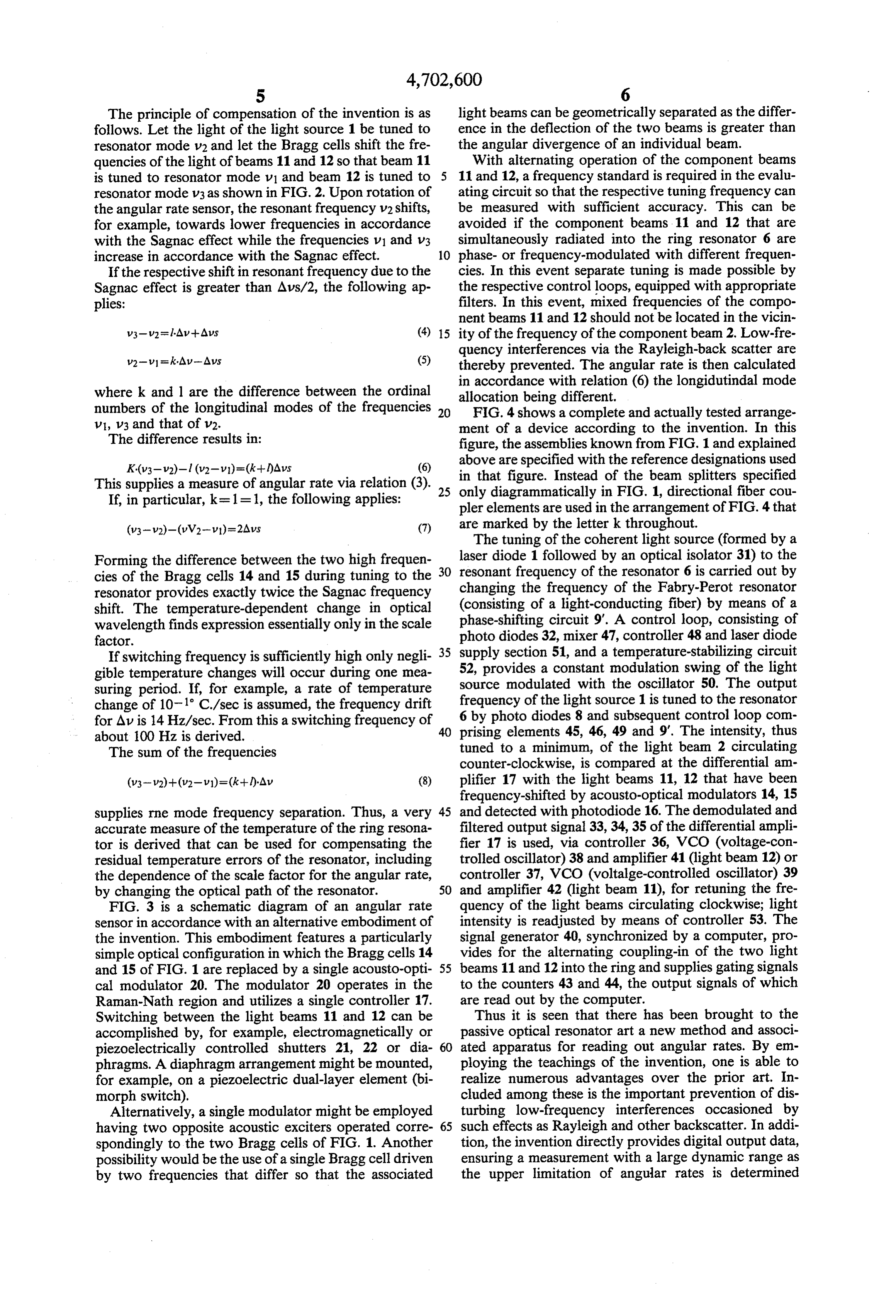
The principle of compensation of the invention is as light beams can be geometrically separated as the differ follows. Let the light of the light source 1 be tuned to ence in the deflection of the two beams is greater than resonator mode v2 and let the Bragg cells shift the fre the angular divergence of an individual beam. quencies of the light of beams 11 and 12 so that beam 11 With alternating operation of the component beams is tuned to resonator mode v1 and beam 12 is tuned to 5 11 and 12, a frequency standard is required in the evalu resonator mode V3 as shown in FIG. 2. Upon rotation of ating circuit so that the respective tuning frequency can the angular rate sensor, the resonant frequency v2 shifts, be measured with sufficient accuracy. This can be for example, towards lower frequencies in accordance avoided if the component beams 11 and 12 that are with the Sagnac effect while the frequencies v1 and v3 simultaneously radiated into the ring resonator 6 are increase in accordance with the Sagnac effect. 10 phase- or frequency-modulated with different frequen If the respective shift in resonant frequency due to the cies. In this event separate tuning is made possible by Sagnac effect is greater than Aus/2, the following ap the respective control loops, equipped with appropriate plies: filters. In this event, mixed frequencies of the compo nent beams 11 and 12 should not be located in the vicin 15 ity of the frequency of the component beam 2. Low-fre quency interferences via the Rayleigh-back scatter are v2-v=k*AV-AVs (5) thereby prevented. The angular rate is then calculated where k and l are the difference between the ordinal in accordance with relation (6) the longidutindal mode numbers of the longitudinal modes of the frequencies 20 allocation being different. FIG. 4 shows a complete and actually tested arrange
V1, v3 and that of v2. ment of a device according to the invention. In this The difference results in: figure, the assemblies known from FIG. 1 and explained K(v3-v2)-l (v2-v)=(k+)Aus (6) above are specified with the reference designations used in that figure. Instead of the beam splitters specified
This supplies a measure of angular rate via relation (3). 25 only
If, in particular, k=1 = 1, the following applies: diagrammatically in FIG. 1, directional fiber cou pler elements are used in the arrangement of FIG. 4 that (v3-v2)-(u V2-v)=2Avs (7) are marked by the letter k throughout. The tuning of the coherent light source (formed by a
Forming the difference between the two high frequen laser diode 1 followed by an optical isolator 31) to the cies of the Bragg cells 14 and 15 during tuning to the 30 resonant frequency of the resonator 6 is carried out by resonator provides exactly twice the Sagnac frequency changing the frequency of the Fabry-Perot resonator shift. The temperature-dependent change in optical (consisting of a light-conducting fiber) by means of a wavelength finds expression essentially only in the scale phase-shifting circuit 9'. A control loop, consisting of factor. photo diodes 32, mixer 47, controller 48 and laser diode If switching frequency is sufficiently high only negli 35 supply section 51, and a temperature-stabilizing circuit gible temperature changes will occur during one mea 52, provides a constant modulation swing of the light suring period. If, for example, a rate of temperature source modulated with the oscillator 50. The output change of 10-1 C./sec is assumed, the frequency drift frequency 6 by photo of the light source 1 is tuned to the resonator diodes 8 and subsequent control loop com for AV is 14 Hz/sec. From this a switching frequency of 40 about 100 Hz is derived. prising elements 45, 46, 49 and 9'. The intensity, thus The sum of the frequencies tuned to a minimum, of the light beam 2 circulating counter-clockwise, is compared at the differential am (v3-v2)+(V2-v)=(k+l)-Av (8) plifier 17 with the light beams 11, 12 that have been frequency-shifted by acousto-optical modulators 14, 15 supplies rne mode frequency separation. Thus, a very 45 and detected with photodiode 16. The demodulated and accurate measure of the temperature of the ring resona filtered output signal 33, 34, 35 of the differential ampli tor is derived that can be used for compensating the fier 17 is used, via controller 36, VCO (voltage-con residual temperature errors of the resonator, including trolled oscillator) 38 and amplifier 41 (light beam 12) or the dependence of the scale factor for the angular rate, controller 37, VCO (voltalge-controlled oscillator) 39 by changing the optical path of the resonator. 50 and amplifier 42 (light beam 11), for retuning the fre FIG. 3 is a schematic diagram of an angular rate quency of the light beams circulating clockwise; light sensor in accordance with an alternative embodiment of intensity is readjusted by means of controller 53. The the invention. This embodiment features a particularly signal generator 40, synchronized by a computer, pro simple optical configuration in which the Bragg cells 14 vides for the alternating coupling-in of the two light and 15 of FIG. 1 are replaced by a single acousto-opti 55 beams 11 and 12 into the ring and supplies gating signals cal modulator 20. The modulator 20 operates in the to the counters 43 and 44, the output signals of which Raman-Nath region and utilizes a single controller 17. are read out by the computer.
Switching between the light beams 11 and 12 can be Thus it is seen that there has been brought to the accomplished by, for example, electromagnetically or passive optical resonator art a new method and associ piezoelectrically controlled shutters 21, 22 or dia 60 ated apparatus for reading out angular rates. By em phragms. A diaphragm arrangement might be mounted, ploying the teachings of the invention, one is able to for example, on a piezoelectric dual-layer element (bi realize numerous advantages over the prior art. In morph switch). cluded among these is the important prevention of dis Alternatively, a single modulator might be employed turbing low-frequency interferences occasioned by having two opposite acoustic exciters operated corre 65 such effects as Rayleigh and other backscatter. In addi spondingly to the two Bragg cells of FIG. 1. Another tion, the invention directly provides digital output data, possibility would be the use of a single Bragg cell driven ensuring a measurement with a large dynamic range as by two frequencies that differ so that the associated the upper limitation of angular rates is determined
Page 9
solely by the amount of mode separation or bandwidth counterrotates simultaneously with said second of the frequency shifting elements, such as Bragg cells, and third beams;
employed. (f) a first photodetector arranged to detect said first By utilizing the teachings of the invention, one is component beam after it is radiated out of said further enabled to compensate the effect of temperature resonator and to form an output electrical signal drift on the measurement of angular rates. Additionally, responsive thereto;
accurate averaged resonator temperature information is (g) a second photodetector arranged to detect said made available for temperature modulation of scale second and third component beams after they are factor, null drift and other factors in accordance with radiated out of said resonator and to form output the invention. 10 electrical signals responsive thereto; While this invention has been disclosed with refer (h) a control circuit responsive to said output signals ence to its presently preferred embodiments, its teach for forming said first and second control signals; ings are by no means so limited. For example, the reso and w
nator 6 need not be an optical fiber but might also com (i) an evaluation circuit responsive to said first and prise a ring optical cavity within a block having three or 15 second control signals, said evaluation circuit being four corrner mirrors for directing laser light. Rather, arranged to determine angular rate as the weighted the scope of this invention is defined by the following difference of the frequency differentials between set of claims and all equivalents thereof. said first and second counterrotating beams and What is claimed is: between said third and first counterrotating beams. 1. A method for reading out angular rates with a 20 4. Apparatus as defined in claim 3 further character passive optical ring resonator said method comprising ized in that said ring resonator comprises a fiber ring of the steps of: strongly birefringent, polarization-maintaining mono (a) providing a beam of coherent light whose fre mode fiber.
quency is a resonant mode of said ring resonator 5. Apparatus as defined in claim 3 further character cavity; then 25 ized in that said ring resonator comprises a fiber ring of (b) dividing said beam into first, second and third strongly polarizing light conducting fiber. component beams; then 6. Apparatus as defined in claim 3 further character (c) radiating said first beam into said resonator in a ized in that said ring resonator includes a polarizer. first direction; then 7. Apparatus as defined in claim 3 wherein said ring (d) tuning the frequency of said second beam to a 30 resonator comprises a resonant cavity. lower resonant cavity mode and tuning the fre 8. Apparatus as defined in claim 7 wherein said reso quency of said third beam to a higher resonant nator further includes three mirrors. cavity mode; then 9. Apparatus as defined in claim 7 wherein said reso (e) alternately radiating said second and third beams nator further includes four mirrors. into said resonator in a second opposite direction so 35 10. Apparatus as defined in claim 3 wherein said ring that said first component beam simultaneously resonator, coupler and frequency shifting devices are counterrotates with one of said second and third fabricated in integrated optics.
component beams to thereby excite different 11. Apparatus as defined in claim 3 wherein said first modes at the same time; then and second frequency shifting devices comprise Bragg (f) measuring a first frequency differential between cells.
said first and second counterrotating beams and a 12. Apparatus as defined in claim 3 wherein said first second frequency differential between said third and second frequency shifting devices comprise an and first counterrotating beams; and then acousto-optical modulator including two acoustical (j) calculating the angular rate as a weighted function exciters.
of said first and second frequency differentials. 45 13. Apparatus as defined in claim 3 wherein said first 2. A method as defined in claim 1 further including and second frequency shifting devices comprise a Bragg the step of calculating the optical length of said resona cell having a plurality of frequency-drive arrangements tor, temperature and scale factor of the angular rate associated therewith.
measurement as the sum of said weighted frequency 14. Apparatus as defined in claim 3 wherein said differentials. 50 means for dividing and said frequency shifting devices 3. Apparatus for reading out angular rates with a consist of an acousto-optical modulator operating in the passive optical ring resonator, said apparatus compris Raman-Nath region.
ing, in combination: 15. Apparatus as defined in claim 3 further including (a) means for generating a beam of coherent light means engaged to said first and second frequency shift whose frequency is a first resonant mode of said 55 ing devices for alternately radiating said second and ring resonator; third beam into said ring resonator at a preselected (b) means for dividing said beam into first, second and frequency. , third component beams; 16. Apparatus as defined in claim 15 wherein said (c) a first frequency shifting device responsive to a last-named means comprises a pair of diaphragms. first control signal for tuning the frequency of said 60 17. Apparatus as defined in claim 16 wherein said second beam to a lower distinct resonant mode of diaphragms are electromagnetically controlled. said resonator; 18. Apparatus as defined in claim 17 wherein said (d) a second frequency shifting device responsive to a diaphragms are piezoelectrically controlled. second control signal for tuning the frequency of 19. Apparatus as defined in claim 3 including means said third beam to a higher distinct resonant mode 65 for modulating said second and third beams so that said of said resonator; beams can be separated by appropriate filtering of said (e) a coupler for radiating said first beam into said output electrical signals.
ring resonator whereby said first beam alternately k sk sk sk sk
Provenance
- Collection
- Cited prior art
- Original PDF
- patentimages.storage.googleapis.com →
- Filed
- 1985-07-19
- Pages
- 9
- Method
- pdftotext (the PDF's own text layer) + pdftoppm 300dpi page scans
- Source
- Google Patents bibliographic record
- Granted
- 1987-10-27
- Inventors
- Eberhard Handrich; Werner Schroder; Litef GmbH
- Transcribed from
- patentimages.storage.googleapis.com →