patent · US2793018
Furnace for the treatment of substances by means of the energy supplied by a concentrated radiation
21 May 1957
Page 1
Drawing sheet — no readable text.
Page 2
Drawing sheet — no readable text.
Page 3
Drawing sheet — no readable text.
Page 4
United States Patent Office 2,793,018 Patented May 21, 1957
2,793,018 tion may vary from some hundreds to some thousands of revolutions per minute.
FURNACE FOR THE TREATMENT OF SUB. The present invention therefore consists in a new ap STANCES BY MEANS OF THE ENERGY plication of rotary furnaces and their adaptation to heat SEED BY A CONCENTRATED RADI. ing and treatment of substances by radiation and in par ticular by solar radiation. Such a rotary furnace has
Felix Trombe, Paris, France, assignor to Centre National over internally heated rotary furnaces as are known at de la Recherche Scientifique, Paris, France, a society the present time the great advantage that it makes it pos of France sible to melt and to treat substances in an atmosphere O which can be chosen at will.
Application July 24, 1953, Serial No. 369,995 As a matter of fact, in the conventional rotary fur Claims priority, application France July 24, 1952 naces, the particular heating requires, inside of the fur nace, an atmosphere of a predetermined nature, whether 7 Claims. (C. 263-7) heating of said furnace is obtained by a flame or by means of a heat radiator electrically brought to a high
It is known that the concentration of a radiation by temperature. Furthermore, the atmosphere is generally means of a suitable optical device, for instance the Soiled (heating by means of a flame or by means of a concentration of Solar energy by means of a parabolic carbon electrode for instance). The furnace according mirror, makes it possible to obtain very high tempera to my invention avoids these drawbacks while making it tures, owing to which the most refractory substances can possible to obtain higher temperatures than with any be melted. other known device.
In what follows, I will refer to solar energy but the For practical purposes, the substance to be treated invention is applicable to all concentrated radiations, for will be in the form of a powder so as to be uniformly instance to the radiations supplied by a high intensity distributed over the wall of the rotary cavity. The tem electric arc or to cathode rays radiations. perature gradient being directed from the inside toward If no special precautions are taken, the high energetic the outside, the device includes in fact three different density of the radiation causes a part of the substance to Zones. The first Zone, constituted by the external en be volatilized during melting. Furthermore, some sub Velope, is at a relatively low temperature. It may be stances reflect or transmit the radiation and retain only cooled by a suitable fluid (air or water for instance), and a small portion of the incident energy. The efficiency 30 is generally constituted by a metal (iron, aluminium, etc.). of the operation therefore depends upon the optical quali The second Zone is constituted by a portion of the pow ties of the matter that is being treated. dery substance applied by centrifugal effect in contact It has been suggested to make use of cavities formed with said external envelope, so that it does not reach in a mass of refractory Substance and efficiently heat melting temperature and constitutes, properly speaking, insulated, such a cavity having a narrow inlet into which 35 the retort in which is melted the substance subjected to the solar radiation converges. The energy then accumu the action of the radiation and which constitutes the third lates in the cavity and the temperature gradually rises Zone of the device. It is again pointed out that a very therein. The rate of heating depends upon the internal great advantage of the invention lies in the fact that the area of the cavity, which area is generally much greater second and the third zones may be constituted by the than the cross section area of the orifice through which 40 same chemical substance. I thus avoid any impurities the radiation enters said cavity. Such a device fully other than those contained in the matter to be treated, avoids the risks of local overheating and there is rela which is of very great advantage in some cases. tively little energy lost through the inlet orifice. Solar The furnace may be made of several portions assem radiation enters the cavity with a concentratin which may bled together for using said furnace and the fact that reach several kilowatts per square centimeter, but the 5 Said furnace can be taken into pieces makes it very easy radiation of the cavity is a black body radiation which to extract the products that are formed. depends only upon the temperature and which is inde This furnace combines the advantages of black body pendent of the nature of the Substances that are treated. heating with those of rotary furnaces, without having the For temperatures averaging 2000 C., for instance, the usual drawbacks of these two methods of heating. loss of energy by radiation is but a small portion of the 50 There are many possible applications of the invention: incident energy. jmelting of refractory mixtures, gradual transformations Such a device therefore has many advantages Such as: at high temperature without volatilizing, treatment of elimination of the thermal shock, losses by radiation in ores, continuous manufacture of pieces of revolution the dependent of the optical properties of the substances that are treated, possibility of bringing simultaneously 55 shape and thickness of which depend upon different fac tors (rate of rotation, density of loading, energetic den to a high temperature important amounts of matters, sity, and so on).
and so on. It is even possible, by a continuous extraction of the However, a difficulty may occur which results from Substances at the rear of the furnace, to make tubes of the possibility of reactions between the substance to be variable thicknesses of refractory substances, such as treated and the substance which constitutes the wall of 60 mullite, alumina, silica, etc. It is also easy to produce the recess. on the substances that are treated gaseous reactions, such The object of the present invention is to eliminate this as the direct combination of oxygen and nitrogen, or to difficulty. produce them in a suitable atmosphere. Finally, owing Other objects of my invention will also appear in to the action of the centrifugal force, it is possible to the course of the following description. 85 separate different phases at high temperatures for in The invention consists chiefly in forming the cavity stance a liquid and a solid, a liquid and another liquid, in a structure turning about an axis passing through the or a liquid and a gas.
orifice through which the radiation enters said cavity, the In particular, it is pointed out that alumina, which is speed of rotation being sufficient to cause the matters con a body which absorbs but very little solar radiation, tained in said cavity, preferably in the form of powders, 70 melts three times quicker in the furnace according to the to be projected and maintained against the inner walls invention than in the atmosphere, under identical condi of the cavity by centrifugal effect. The speed of revolu tions.
Page 5
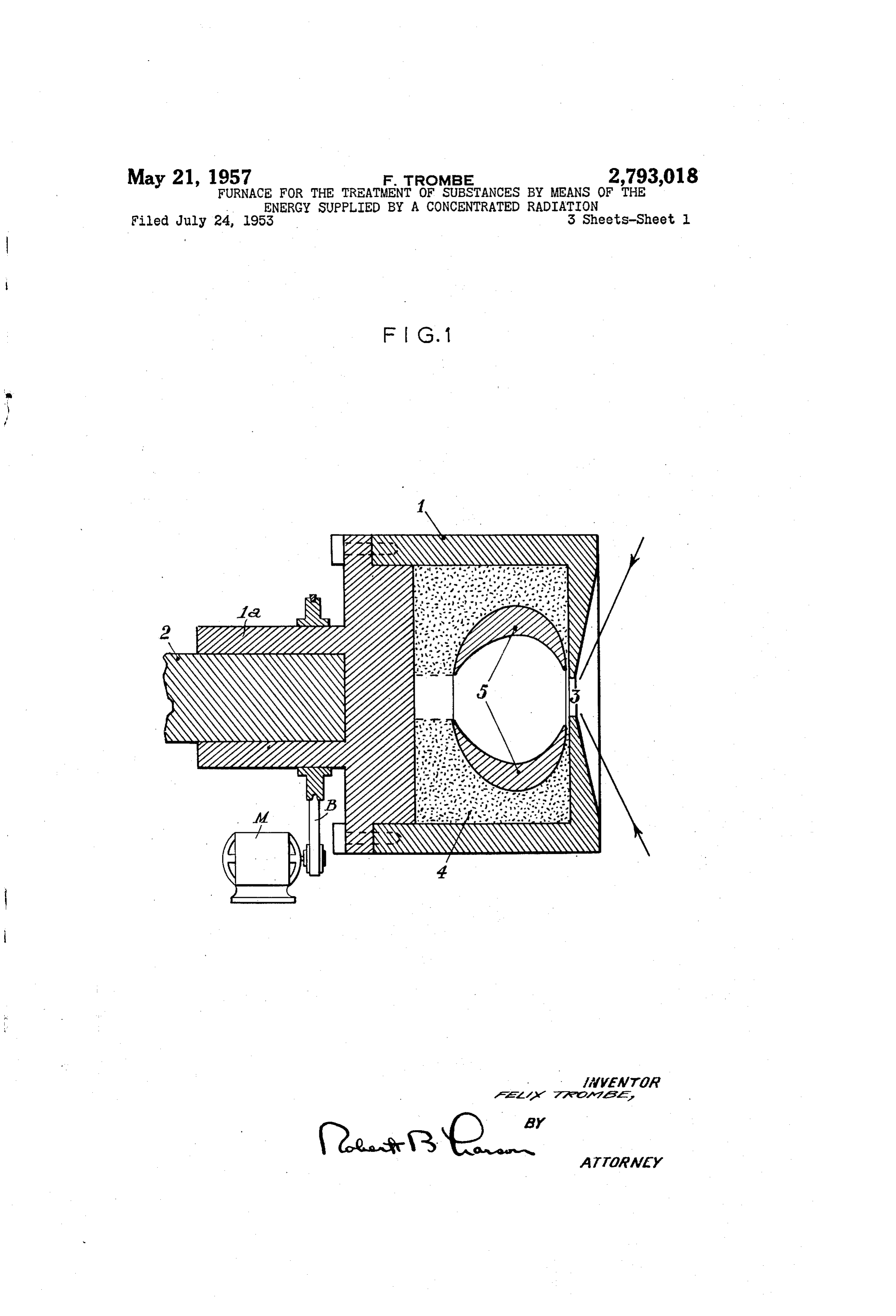
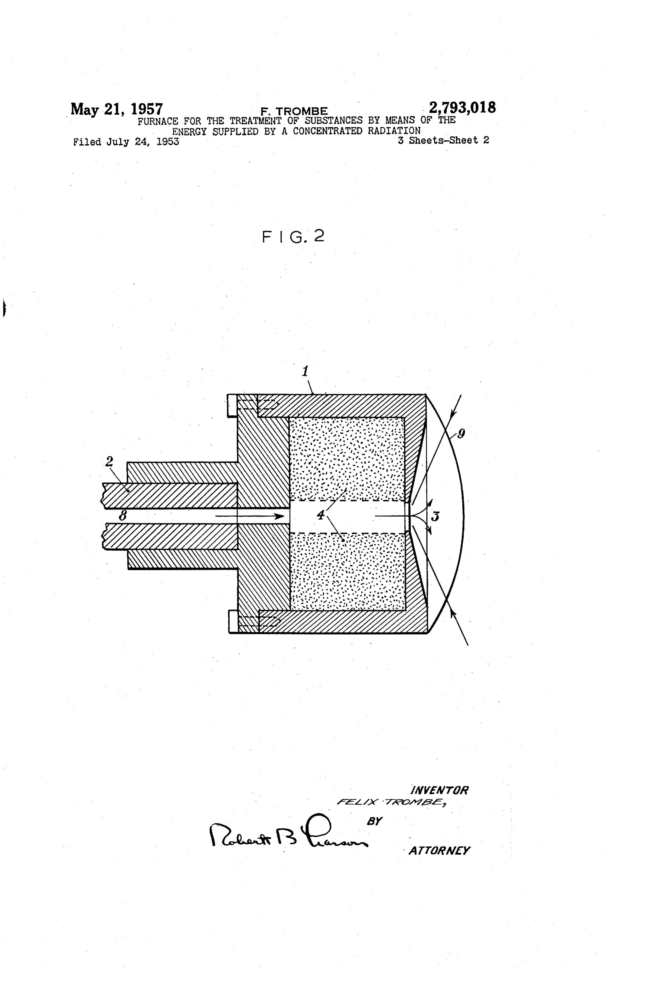
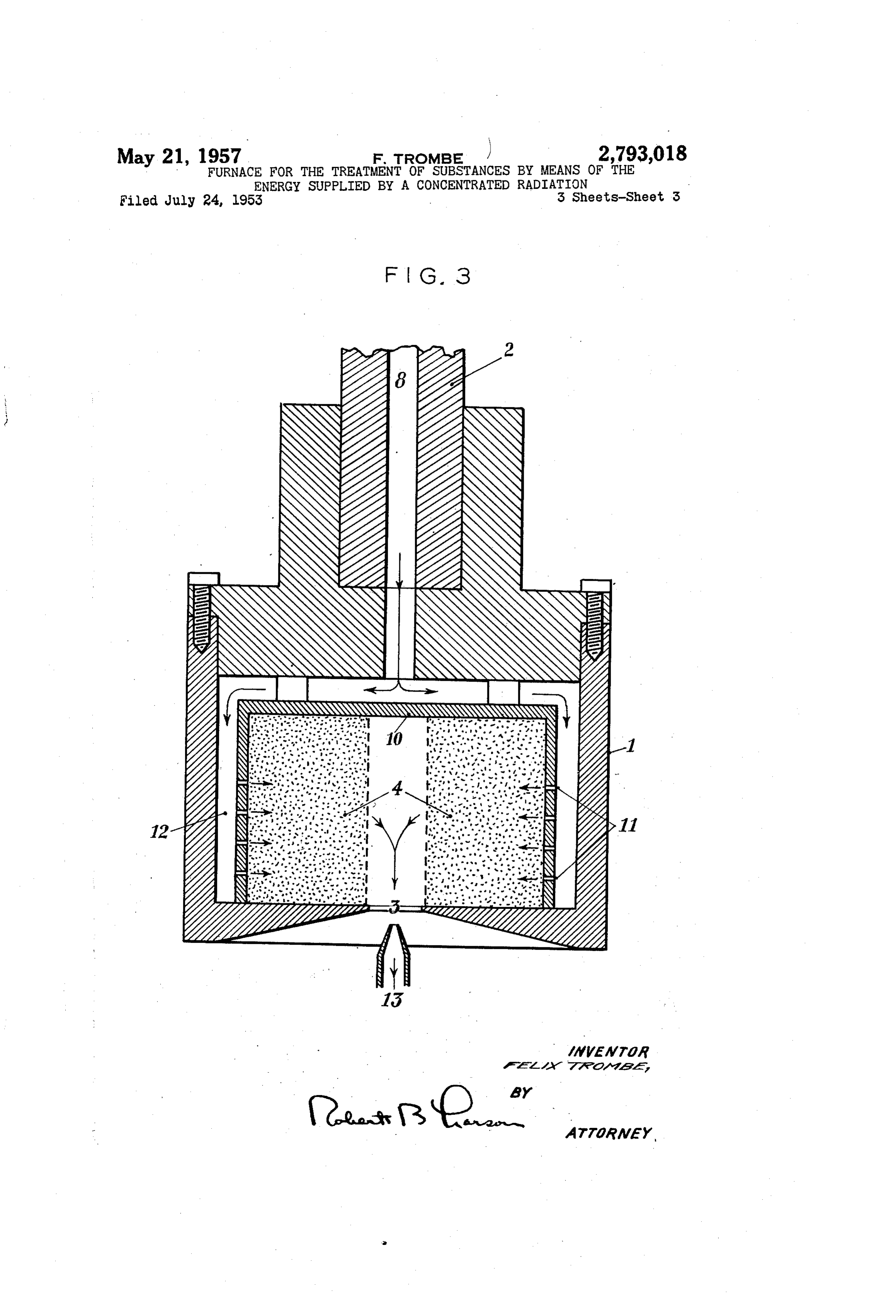
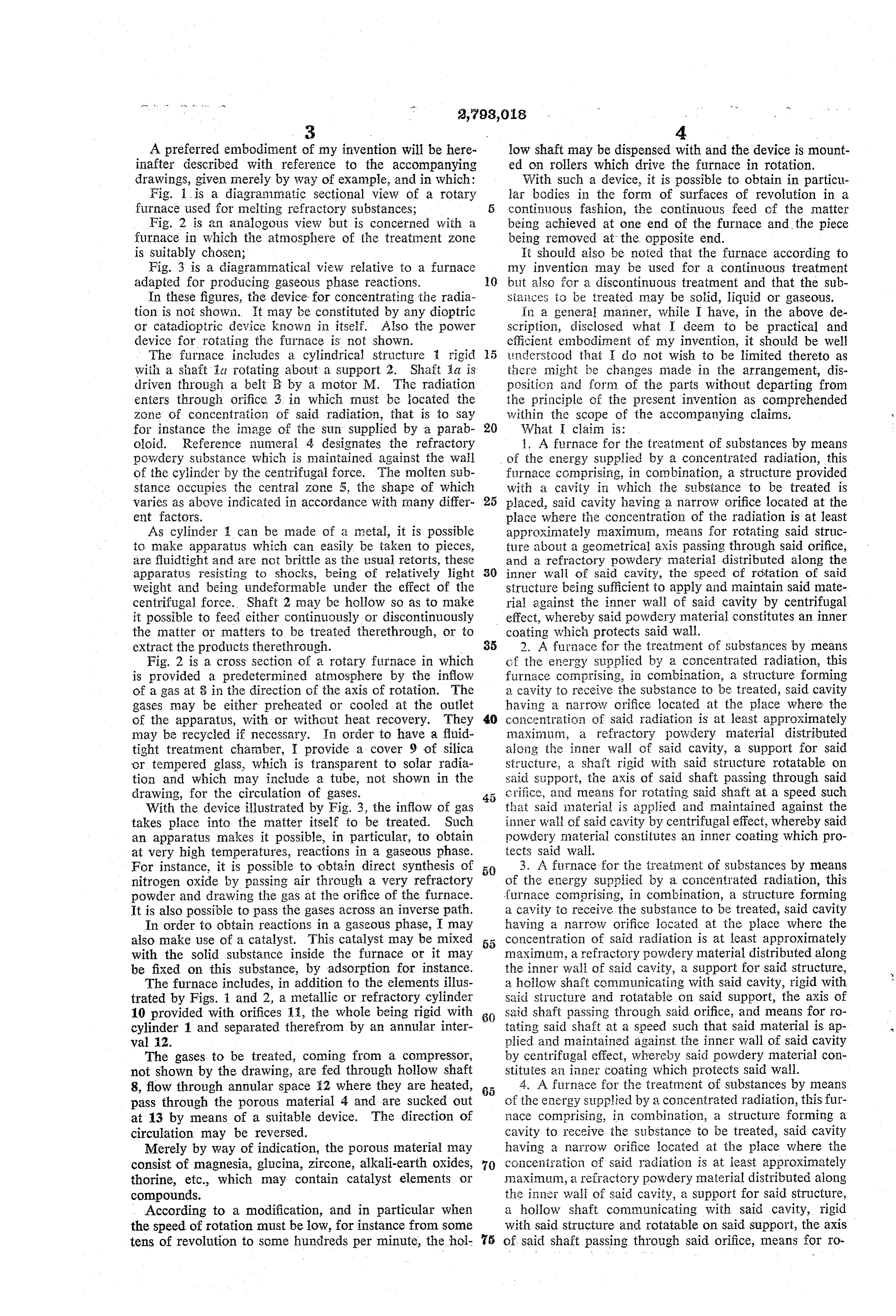
A preferred embodiment of my invention will be here low shaft may be dispensed with and the device is mount inafter described with reference to the accompanying ed on rollers which drive the furnace in rotation. drawings, given merely by way of example, and in which: With such a device, it is possible to obtain in particu Fig. 1 is a diagrammatic sectional view of a rotary lar bodies in the form of surfaces of revolution in a furnace used for neiting refractory Substances; continuous fashion, the continuous feed of the matter Fig. 2 is an analogous view but is concerned with a being achieved at one end of the furnace and the piece furnace in which the atmosphere of the treatinent Zone being removed at the opposite end. is suitably chosen; It should also be noted that the furnace according to Fig. 3 is a diagrammatical view relative to a furnace my invention may be used for a continuous treatment adapted for producing gaseous phase reactions. O but also for a discontinuous treatment and that the Sub In these figures, the device for concentrating the radia Staices to be treated may be solid, liquid or gaseous. tion is not shown. It may be constituted by any dioptric in a general manner, while I have, in the above de or catadioptric device known in itself. Also the power Scription, disclosed what deem to be practical and device for rotating the furnace is not shown. efficient embodiment of my invention, it should be well The furnace includes a cylindrical structure rigid inderstood that I do not wish to be limited thereto as with a shaft a rotating about a support 2. Shaft a is there might be changes made in the arrangement, dis driven through a belt R by a motor M. The radiation positic; and form of the parts without departing from enters through orifice 3 in which must be located the the principle of the present invention as comprehended Zone of concentration of said radiation, that is to say within the scope of the accompanying claims. for instance the image of the Sun Supplied by a parab 20 What claim is:
ooid. Reference inuneral 4 designates the refractory 1. A furnace for the treatment of substances by means powdery substance which is maintained against the wall of the energy Supplied by a concentrated radiation, this of the cylinder by the centrifugal force. The molten sub furnace comprising, in combination, a Structure provided stance occupies the central zone 5, the shape of which with a cavity in which the Substance to be treated is varies as above indicated in accordance with many differ. 25 placed, said cavity having a narrow orifice located at the ent factors. place where the concentration of the radiation is at least As cylinder can be made of a metal, it is possible approximately maximun, means for rotating said struc to make apparatus which can easily be taken to pieces, ture about a geometrical axis passing through said orifice, are fluid tight and are not brittle as the usual retorts, these and a refractory powdery materiai distributed along the apparatus resisting to shocks, being of relatively light 30 inner wall of said cavity, the speed of rotation of said weight and being undeformable under the effect of the structure being sufficient to apply and maintain said mate centrifugal force. Shaft 2 may be hollow so as to make ria against the inner wall of said cavity by centrifugal it possible to feed either continuously or discontinuously effect, whereby said powdery material constitutes an inner the matter or matters to be treated therethrough, or to coating which protects said wall. extract the products therethrough. 35 2. A furnace for the treatment of substances by means Fig. 2 is a cross Section of a rotary furnace in which of the energy supplied by a concentrated radiation, this is provided a predetermined atmosphere by the inflow furnace comprising, in combination, a structure forming of a gas at 8 in the direction of the axis of rotation. The a cavity to receive the substance to be treated, said cavity gases may be either preheated or cooled at the outlet having a narrow crifice located at the place where the of the apparatus, with or without heat recovery. They 40 concentration of said radiation is at least approximately may be recycled if necessary. In order to have a fluid maximun, a refractory powdery material distributed tight treatment chamber, I provide a cover 9 of silica along the inner wall of said cavity, a Support for said or tempered glass, which is transparent to Solar radia structure, a shaft rigid with said structure rotatable on tion and which may include a tube, not shown in the said Sipport, the axis of said shaft passing through said drawing, for the circulation of gases. crifice, and means for rotating said shaft at a speed such With the device illustrated by Fig. 3, the inflow of gas that said laterial is applied and maintained against the takes place into the matter itself to be treated. Such inner waii of said cavity by centrifugal effect, whereby said an apparatus makes it possible, in particular, to obtain powdery material constitutes an inner coating which pro at very high temperatures, reactions in a gaseous phase. tects said wall.
For instance, it is possible to obtain direct synthesis of 50 3. A furnace for the treatment of Substances by means nitrogen oxide by passing air through a very refractory of the energy supplied by a concentrated radiation, this powder and drawing the gas at the orifice of the furnace. furnace comprising, in combination, a structure forming It is also possible to pass the gases across an inverse path, a cavity to receive the Substance to be treated, said cavity In order to obtain reactions in a gaseous phase, I may having a narrow orifice located at the place where the also make use of a catalyst. This catalyst may be mixed concentration of said radiation is at least approximately with the solid substance inside the furnace or it may maximum, a refractory powdery material distributed along be fixed on this substance, by adsorption for instance. the inner wall of said cavity, a Support for said structure, The furnace includes, in addition to the elements illus a hollow shaft communicating with said cavity, rigid with trated by Figs. 1 and 2, a metallic or refractory cylinder said structure and rotatable on said support, the axis of 10 provided with orifices 11, the whole being rigid with O said shaft passing through said orifice, and means for ro cylinder 1 and separated therefrom by an annular inter tating said shaft at a speed such that said material is ap val. 2. plied and maintained against the inner wall of said cavity The gases to be treated, coming from a compressor, by centrifugal effect, whereby said powdery material con not shown by the drawing, are fed through hollow shaft stitutes an inner coating which protects said wail. 8, flow through annular space 2 where they are heated, 65 4. A furnace for the treatment of Substances by means pass through the porous material 4 and are sucked out of the energy Supplied by a concentrated radiation, this fur at 13 by means of a suitable device. The direction of inace comprising, in combination, a structure forming a circulation may be reversed. cavity to receive the Substance to be treated, said cavity Merely by way of indication, the porous material may having a narrow orifice located at the place where the consist of magnesia, glucina, zircone, alkali-earth oxides, O concentration of said radiation is at least approximately thorine, etc., which may contain catalyst elements or maximum, a refractory powdery material distributed along compounds. the inner wall of said cavity, a support for said structure, According to a modification, and in particular when a hollow shaft communicating with said cavity, rigid the speed of rotation must be low, for instance from some with said structure and rotatable on said support, the axis tens of revolution to some hundreds per minute, the hol s of said shaft passing through said orifice, means for ro
Page 6
tating said shaft at a speed such that said material is ap said material is applied and maintained against the in plied and maintained against the inner wall of said cavity ner wall of said cavity by centrifugal effect, whereby said by centrifugal effect, whereby said powdery material powdery material constitutes an inner coating which pro constitutes an inner coating which protects said wall, and tects said wall, and a tempered glass cover disposed a fixed conduit opening opposite said orifice to cooperate 5 above said orifice.
with the conduit constituted by said hollow shaft. 7. A furnace for the treatment of substances by means 5. A furnace for the treatment of substances by means of the energy Supplied by a concentrated radiation, this of the energy supplied by a concentrated radiation, this furnace comprising, in combination, a structure forming furnace comprising, in combination, a structure forming a cavity to receive the substance to be treated, said cavity a cavity to receive the substance to be treated, said cavity 10 having a narrow orifice located at the place where the having a narrow orifice located at the place where the concentration of said radiation is at least approximately concentration of said radiation is at least approximately maximum, the side wall of said cavity being provided maximum, a refractory powdery material distributed along with a multiplicity of orifices, another wall included in the inner wall of said cavity, a support for said structure, said structure surrounding said first mentioned wall to a shaft rigid with said structure rotatable on said support, form an annular space around it, a refractory powdery the axis of said shaft passing through said orifice, means material distributed along the inner wall of said cavity, for rotating said shaft at a speed such that said material a Support for said structure, a hollow shaft communicat is applied and maintained against the inner wall of said ing with said annular space, rigid with said structure and cavity by centrifugal effect, whereby said powdery mate rotatable on said Support, the axis of said shaft passing rial constitutes an inner coating which protects said wall, 20 through said orifice, means for rotating said shaft at a and a silica cover disposed on said orifice. speed such that said material is applied and maintained 6. A furnace for the treatment of substances by means against the inner wall of said cavity by centrifugal effect, of the energy supplied by a concentrated radiation, this whereby said powdery material constitutes an inner coat furnace comprising, in combination, a structure forming ing which protects said wall, and means for circulating a a cavity to receive the substance to be treated, said cavity 25 gas through said hollow shaft.
having a narrow orifice located at the place where the concentration of said radiation is at least approximately References Cited in the file of this patent maximum, a refractory powdery material distributed UNITED STATES PATENTS along the inner wall of said cavity, a support for said structure, a shaft rigid with said structure rotatable on 30 797,891 Himalaya -------------- Aug. 22, 1905 said support, the axis of said shaft passing through said 1,684,800 Maximoff-------------- Sept. 18, 1928 orifice, means for rotating said shaft at a speed such that 2,557,971 Jacklin ---------------- June 26, 1951
Provenance
- Collection
- Cited prior art
- Original PDF
- patentimages.storage.googleapis.com →
- Filed
- 1953-07-24
- Pages
- 6
- Method
- pdftotext (the PDF's own text layer) + pdftoppm 300dpi page scans
- Source
- Google Patents bibliographic record
- Granted
- 1957-05-21
- Inventors
- Trombe Felix; Centre National de la Recherche Scientifique CNRS
- Transcribed from
- patentimages.storage.googleapis.com →