patent · US2707519
Automatic pilot and ignition systems for fuel burner
3 May 1955
Page 1
Drawing sheet — no readable text.
Page 2
United States Patent Office 2,707,519 Patented May 3, 1955
The actuating element 26 is supported in a casing 30 on one side of a partition 32 therein which is provided 2,707,519 with an axial opening 34. The partition 32 defines, on
AUTOMATIC PILOT AND IGNITION SYSTEMS 5 the side thereof opposite the actuating element 26, a seat FOR FUEL BURNER for a valve member 36 which is biased to a position for closing the opening 34 by means of a valve spring 38. A
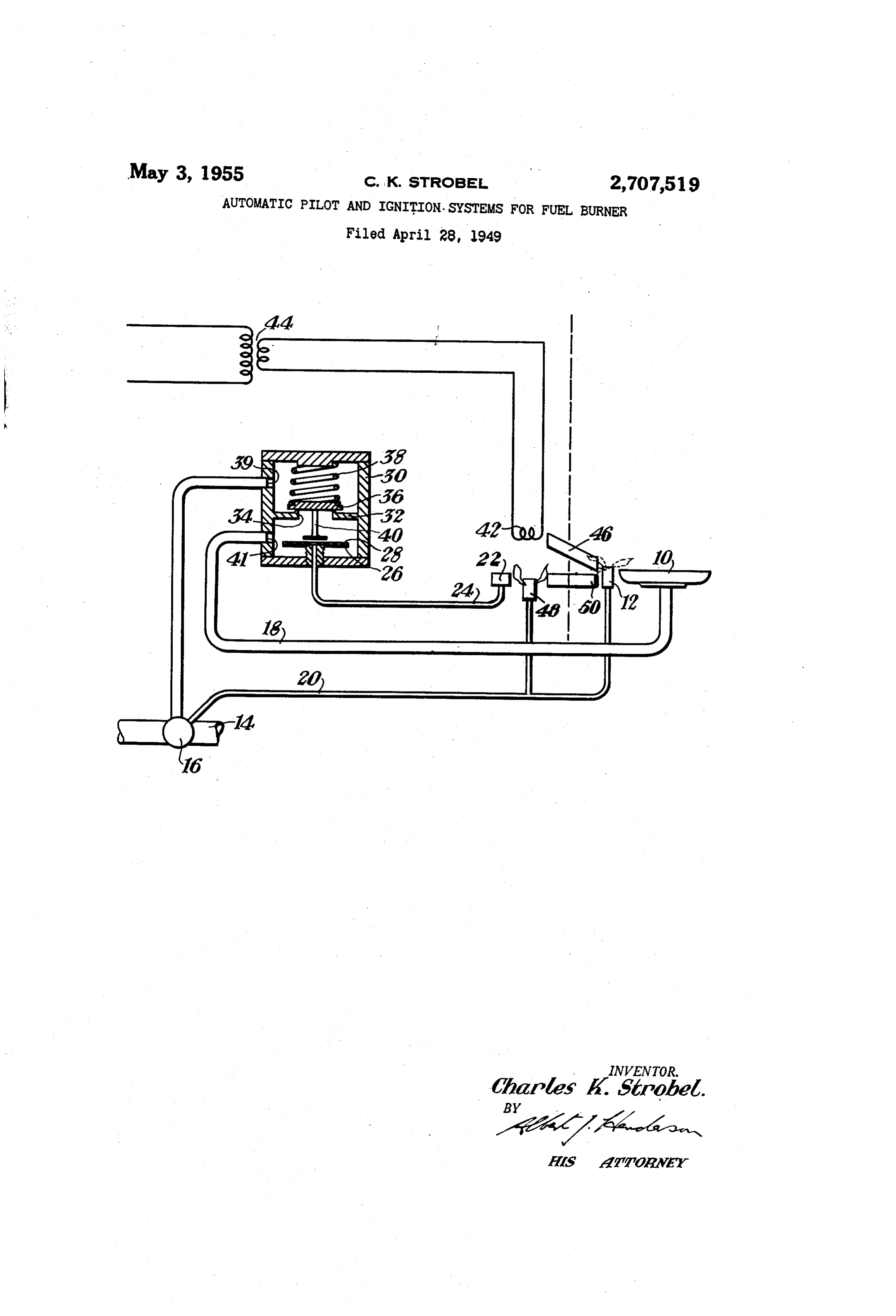
Charles K. Strobel, Pittsburgh, Pa., assignor to Robert valve stem 40 projects from the underside of the valve shaw-Fulton Controls Company, Greensburg, Pa., a member 36 through the opening 34 to adjacent the actuat corporation of Delaware ing element 26, but is preferably slightly spaced from the Application April 28, 1949, Serial No. 90,152 10 diaphragm 28 thereof. The construction is intended to be such as to prevent operation of the valve member 36 1 Claim. (Cl. 158-143) by the actuating element 26 until such time as rapid vaporization of the mercury in the thermal element has commenced.
As disclosed in my copending application Serial No. The casing 30 is interposed in the main fuel pipe 18 90,151 filed of even date herewith, a catalytic ignition in Such manner that the valve member 36 can control System with flash tubes can be combined with an auto the flow of fuel between the combined thermostat and matic pilot control to provide automatic ignition for fluid gas cock 16 and the main burner 10. To this end, one fuel burners while preventing the escape of unburned portion of the main fuel pipe 18 forms an inlet 39 com fuel. The present invention includes in such systems municating with the interior of the casing 30 on one side provision for instantaneous recycling in the event of flame of the partition 32 while the opposite end of the main failure and an instantaneous resetting operation in the fuel pipe 18 forms an outlet 4 communicating with the event of rapid off-on operation under steady state oper interior of the casing 30 on the other side of the partition ating conditions. 32. Consequently, when the valve member 36 is in the With these and other objects in view, the preferred em closed position shown in the drawing no flow of fuel to bodiment utilizes an electrically energized “hot” type the main burner 10 can occur. However, upon suitable catalytic igniter which is adapted to ignite an oven pilot expansion of the actuating element 26 and corresponding burner through a flash tube and thus cause operation of movement of the diaphragm 28 thereof, the bias of the an hydraulic type pilot control to admit fuel to the main valve spring 38 is overcome and the valve member 36 burner. The igniter is continuously energized and its : is moved to open position relative to the opening 34. temperature is raised to ignition value only when un Under such circumstances flow of fuel to the main burner burned fuel impinges upon it. Consequently, a pilot 0 can occur provided, of course, that the fuel cock asso outage results in immediate reignition as does a rapid ciated with the combined valve and fuel cock 16 is in off-on operation during steady state conditions, even open position or the thermostat portion thereof is not though the pilot control has not had time to shut off the operating to shut off the flow of fuel. main burner fuel. The ignition system of the apparatus comprises an elec The accompanying drawing which is a schematic view trically energized igniter 42 which is formed of catalytic of the automatic pilot and ignition apparatus in conjunc material. No particular forms of “hot” type catalytic tion with a gaseous fuel burner shows by way of example igniters need be described in detail herein as such devices the preferred embodiment of the invention. 40 are Well-known. Suffice it to say that the active com Referring more particularly to the drawing, the oven ponents may comprise small pellets of activated platinum burner 10 is positioned in the oven compartment of a gas or other suitable catalytic material supported on a plati range as indicated by the broken lines in the drawing. A num or other wire of suitable catalytic material. When pilot burner 12 is positioned in lighting proximity to the a combustible gas-air mixture impinges on such an igniter main burner 10 and both burners are adapted to receive 45 the small pellets become sufficiently hot to increase the a supply of fuel from the usual manifold 14. Thus, a temperature of the wire to the point where catalytic combined thermostatic valve and gas cock 16, such as dis action occurs. Consequently, the wire attains the re closed in Weber Patent No. 2,303,011, may be incor quired temperature and ignition of the combustible mix porated in the manifold 14 with a supply pipe 18 for the ture takes place. As previously indicated, the structure main burner 10 and a by-pass 20 for the pilot burner 12. of the igniter 42 forms no part of the present invention. The arrangement is such that the flow of fuel through the The igniter 42 is energized continuously from a suit by-pass 20 to the pilot burner 12 is not interrupted or able source of current supply through a transformer 44. throttled by thermostatic operation as is the flow of fuel In this embodiment, the transformer 44 is of the step in the main fuel pipe 18. down type and the secondary thereof need only have a The automatic control associated with the pilot burner 55 rating of about two volt-amperes. As indicated in the 12 takes the form of a vapor-pressure thermal element drawing, the igniter 42 is connected in series circuit with comprising a bulb 22, capillary tube 24, and expansible the secondary of transformer 44 and is located exterior actuating element 26. The bulb. 22 in this embodiment of the oven compartment. Consequently, a short flash is located exterior of the oven compartment to be heated tube 46 is positioned in the oven wall between the igniter by a flame from a heater pilot burner 48 which is also 60 42 and the pict burner 12 for effecting ignition of the connected to the by-pass 20 to receive a supply of fuel latter. Similarly, a short flash tube 50 is positioned in substantially simultaneously with the pilot burner 12. the oven wall between the pilot burner 12 and the aux The thermal element so constructed operates on well iliary pilot burner 48 for lighting the latter after ignition known principles and contains a partial filling of iner of the pilot burner i2.
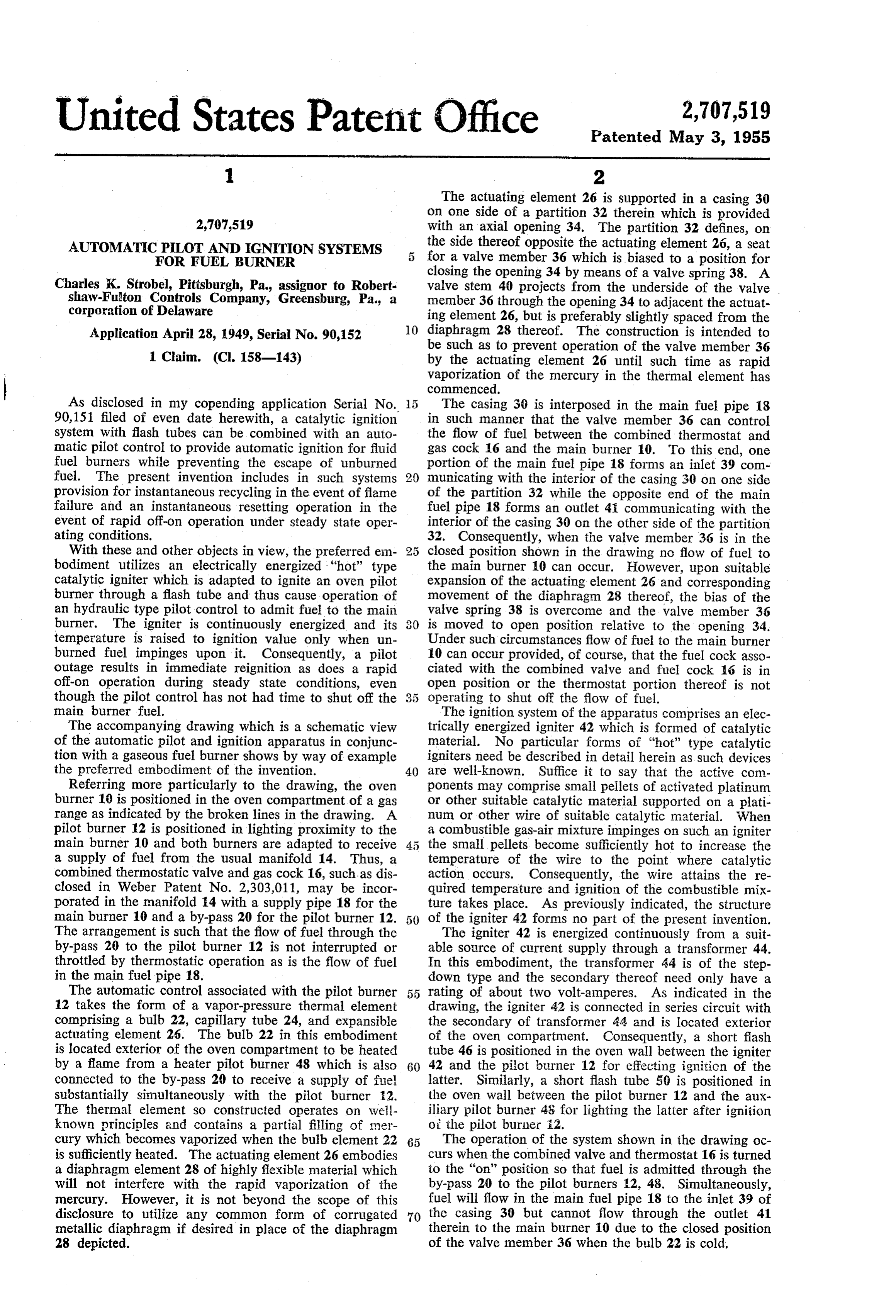
cury which becomes vaporized when the bulb element 22 The operation of the system shown in the drawing oc is sufficiently heated. The actuating element 26 embodies curs when the combined valve and thermostat 16 is turned a diaphragm element 28 of highly flexible material which to the “on” position so that fuel is admitted through the will not interfere with the rapid vaporization of the by-pass 20 to the pilot burners 2, 48. Simultaneously, mercury. However, it is not beyond the scope of this fuel will flow in the main fuel pipe 18 to the inlet 39 of disclosure to utilize any common form of corrugated 70 the casing 30 but cannot flow through the outlet 41 metallic diaphragm if desired in place of the diaphragm therein to the main burner 10 due to the closed position 28 depicted. of the valve member 36 when the bulb 22 is cold,
Page 3
The fuel flowing from the pilot burner 12 enters the thermost at 16 to open the circuit of the primary of thc flash tube 46 and is ignited by the igniter 42 due to the transformer 44 when the oven compartment is not in catalytic action previously described. The resulting flame use. On the other hand, it would be advantageous to travels back through the flash tube 46 and causes ignition utilize the system as shown without such a switch so of the pilot burner 12. The fuel supplied to the heater 5 that a second igniter could also be connected across the pilot burner 48 is in turn ignited from the pilot burner Secondary of the transformer 44 to provide ignition for 12 through the flash tube 50. Shortly thereafter the bulb the usual top burner elements of the gas stove without 22 of the thermal element becomes sufficiently heated the use of switching devices on the top burner gas cocks. by the flame now present at the pilot burner 48 to vapor In such event the second igniter would be used to replace ize the mercury therein and expand the actuating element () the customary top burner pilot and ignite the top burners 26. The corresponding movement of the diaphragm 28 through short flash tubes, as will be apparent. of the actuating element 26 causes opening of the valve In case of the illustrated embodiment of the invention member 36 and admission of fuel from the outlet 4 to many changes may be made in the details of construction the main burner 10. As the fuel flowing from the main and arrangement of parts without departing from the burner 10 is immediately ignited by the pilot burner 12, Scope of the invention so that this description and ac the system is set in steady state operation. companying drawing is intended by way of illustration During such steady state operation under control of only and is not to be construed in a limiting sense. the thermostat combined with the main fuel cock 16, I claim:
the oven compartment is maintained at the desired tem An ignition and automatic pilot control for gaseous perature. It should be noted that at no time during such 2 fuel burners having a main burner and a pilot burner steady state operation, or when the oven is cold, is the located within an oven compartment comprising an elec catalytic igniter 42 operated beyond a relatively low tem tric catalytic igniter adapted to be located exterior of perature which may be approximately 900 degrees F. the compartment, means for constantly energizing said The temperature of such an electrically energized cata igniter below igniting temperature, a flash tube for con lytic igniter is only raised to ignition values when un 2 5 veying a combustible mixture from the pilot burner to burned fuel impinges upon it. adjacent said igniter and producing a flame at the pilot In case of flame failure, the fuel flowing from the pilot burner, an auxiliary pilot burner located without the burner 12 will immediately be reignited through the flash oven compartment, a second flash tube extending between tube 46 by operation of the igniter 42. In case of ignition said pilot burners for producing a flame at said auxiliary failure such as may be caused by breakage of the igniter 30 pilot burner, and means responsive to the presence or ab 42 when the bulb 22 is heated, then this latter element sence of a flame at said auxiliary pilot burner for con will cool and cause closure of the valve member 36. The trolling the fuel supply to the main burner. disclosed embodiment of this invention reduces the effects of a possible delayed ignition in the case of flame failure References Cited in the file of this patent by providing for rapid cooling of the flame sensitive ele 35 UNITED STATES PATENTS ment 22 located exteriorly of the oven compartment 1,173,851 Owen ---------------- Feb. 29, 1916 where the temperature of the atmosphere is somewhat 1,474,641 Powers -------------- Nov. 20, 1923 cooler than the interior thereof. In the event that the 1,751,688 Eggleston ------------ Mar. 25, 1930 main fuel cock 16 is operated from open to closed posi 2,014,848 Kahn ---------------- Sept. 17, 1935 tion and then immediately back to open position so that 40 2,072,034 Geurink et al. ---------- Feb. 23, 1937 a rapid off-on operation from steady state conditions is 2,078,576 Laghetto -------------- Apr. 27, 1937 conducted, then the pilot burner 12 will immediately be 2,083,789 Matthews ------------ June 15, 1937 reignited by the igniter 42 even though the valve member 2,087,433 Hollman -------------- July 20, 1937 36 has not had time to move to its closed position. 2,269,356 Beam et al. ------------ Jan. 6, 1942 It is apparent that the foregoing described System pro 2,407,729 Taylor -------------- Sept. 17, 1946 vides for both instantaneous recycling and instantaneous 2,487,752 Cohn ---------------- Nov. 8, 1949 reset with no purge period needed as previously indi 2,520,299 Antrim -------------- Aug. 29, 1950 cated. Furthermore, the system has the particular ad vantage of requiring no electrical contacts or electrical FOREIGN PATENTS switches. However, it is not beyond the scope of this 463,276 Great Britain ---------- Mar. 26, 1937 disclosure to provide a switch on the combined valve and
Provenance
- Collection
- Cited prior art
- Original PDF
- patentimages.storage.googleapis.com →
- Filed
- 1949-04-28
- Pages
- 3
- Method
- pdftotext (the PDF's own text layer) + pdftoppm 300dpi page scans
- Source
- Google Patents bibliographic record
- Granted
- 1955-05-03
- Inventors
- Charles K Strobel; Robertshaw Fulton Controls Co
- Transcribed from
- patentimages.storage.googleapis.com →