patent · US3323886
Radiation absorption heating of a bundle of glass fibers
6 June 1967
Page 1
June 6, 1967 F, R, HAYS 3,323,886
RADIATION ABSORPTION HEATING OF A BUNDLE OF GLASS FIBERS
Filed May 1, 1963 4. Sheets-Sheet l
---a 2C2 4. Y 22 369 2s Rats etx4r14AYZR 7tk-e Z-Car
SSS
£32 SaaS A. NVENTOR
Y 20 % ao FREDERICK R. HAYS
225 226 "/4.4-Y ATTORNEY
Page 2
Drawing sheet — no readable text.
Page 3
Drawing sheet — no readable text.
Page 4
Drawing sheet — no readable text.
Page 5
United States Patent Office 3,323,886 Patented June 6, 1967
tions thereof.
uniformly heated throughout all cross sec
RADATION ABSORPTION HEATING OF A
BUNDLE OF GLASS FIBERS In general, this is accomplished by providing fiber Frederick R. Hays, Woodstock, Conn., assignor to Amer optical Structures whose absorption coefficient progres ican Optical Company, Southbridge, Mass., a voluntary Sively increases as the depth of the structure increases from association of Massachusetts
Fied May 1, 1963, Ser. No. 277,319 the outermost fibers thereof to the centermost fibers there by to balance the heat absorbed at all depths.
5 (Claims. (CI. 65-4) In accordance with principles of the invention, com ponents having relatively high infrared absorbing proper
This invention relates to fiber optical devices and has O ties particular reference to improvements in fused fiber sivelyareincreasing placed in the fiber optical structures in progres numbers and progressively closer spaced optical image transfer devices and a method for manu relation to each other as the center or axis of the particular facturing the same.
Fused fiber optical image transfer devices are formed of Structure is approached. The infrared absorbing com a multiplicity of optical fibers each having a core of heat 15 ponents optical reradiate to neighboring fibers when the fiber structure is subjected to furnace radiation for fus softenable light-transmitting material of a relatively high ing and thereby tend to equalize temperature distribution index of refraction surrounded by a cladding of heat in the structure.
softenable light-transmitting material of relatively low In one embodiment of the invention, the claddings of index of refraction. The fibers are secured together in Selected inner fibers of a bundle thereof to be fused can bundled side-by-side relation, by fusing the fiber claddings 20 together, so that corresponding opposite ends of the haveto areradiate higher absorption coefficient for the infrared so fibers cooperate to define mosaic image receiving and as to neighboring fibers. In another embodi ment, the core parts of certain selected fibers in a bundle image emitting opposite end faces.
In fusing such bundles of fibers, particularly those of thereof can have the higher coefficient for the infrared or alternatively, relatively high infrared absorbing fila large diameter and formed of relatively long fibers, a heat 25 ments can be placed between certain of the inwardly dis distribution problem exists which, heretofore, has resulted posed clad in a tendency to overfuse or distort the outermost fibers of the abovefibers of a bundle to be fused. Combinations approaches can also be employed.
of a bundle while the more centrally located fibers are The present invention will be more fully understood by underfused and often not completely or hermetically joined together. This is the result of the heat or furnace 30 reference accompanied to the following detailed description which is by a drawing in which:
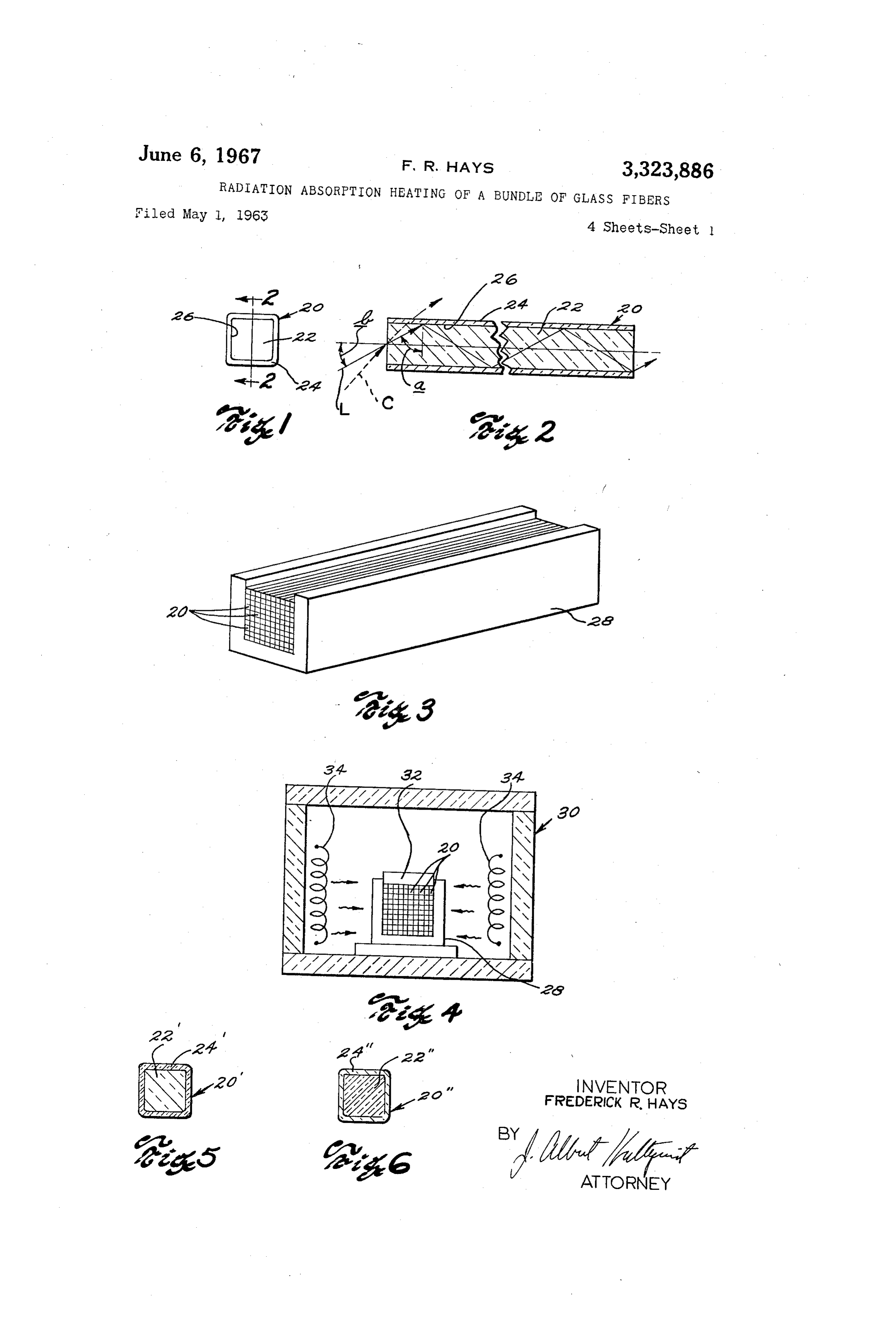
radiation having to be introduced radially through the FIG. 1 is a greatly enlarged end view of an individual sides of the bundle of fibers wherein radiation used for effecting fusion is gradually absorbed and reduced in in optical fiber, of a fiber optical device constructed accord tensity as it penetrates into the bundle. At any radial ing f to principles of the present invention;
2 is a cross-sectional view taken on line. 2-2 of depth in a bundle of fibers, the heat generated is propor 35 . 1;
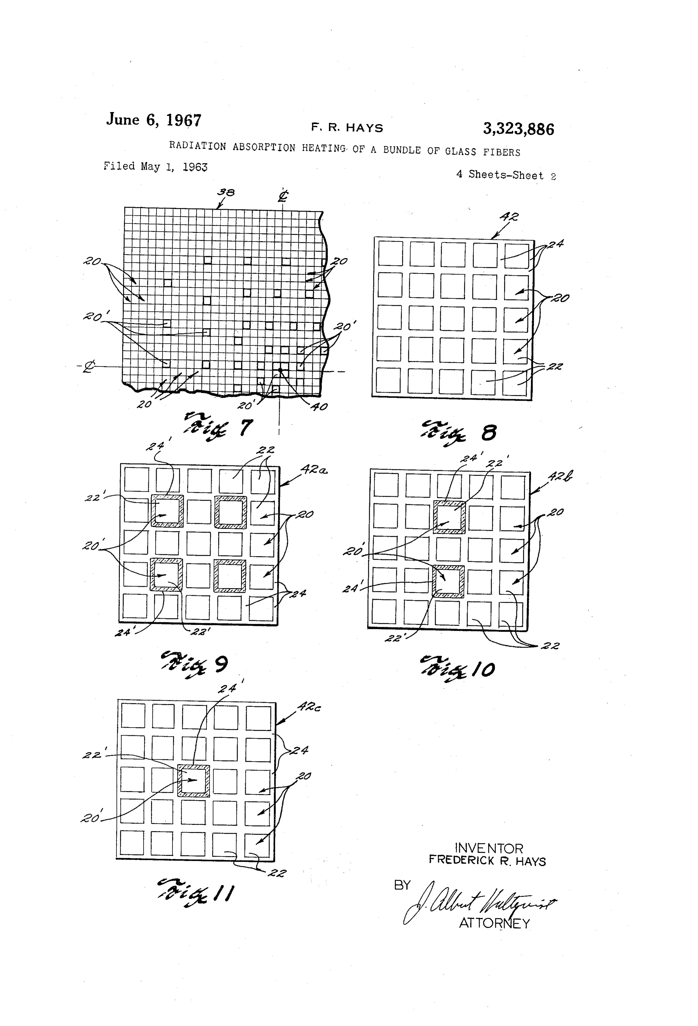
tional to the absorption coefficient of the fibers in the FIG. 3 is a perspective illustration of a bundle of such bundle times the intensity of radiation at that depth. fibers positioned in supporting means therefor; Since all of the fibers of conventional structures are FIG. 4 is a diagrammatic illustration of furnace means formed of the same materials or of the same combinations of materials, the absorption coefficient of all depths in a 40 useful in effecting fusion of such a bundle of fibers; FIGS. 5 and 6 are enlarged cross-sectional views of bundle thereof is substantially the same. Consequently, modified optical fibers useful in the fabrication of modi absorption of furnace radiation as it penetrates the bundle fications of the present invention; results in uneven heat distribution in the bundle with less FIG. 7 is a fragmentary diagrammatic end view of an heat being generated internally thereof and the tendency assembly of optical fibers of one embodiment of the for the innermost fibers of the bundle to be underfused 45 while outermost fibers thereof are overfused. invention;
It is an object of this invention to provide improved FIGS. 8-11 are greatly enlarged diagrammatic end fiber optical devices of the fused type; to provide such views devices of multifiber structures useful in the fabrication of of the invention;
devices which are uniformly fused throughout all depths 50 FIG. 12 is a fragmentary diagrammatic end view of an thereof and to provide a simple, efficient and economical method of making such devices of consistently high assembly FIGS. 8-11;
of multifiber structures of the type illustrated in quality.
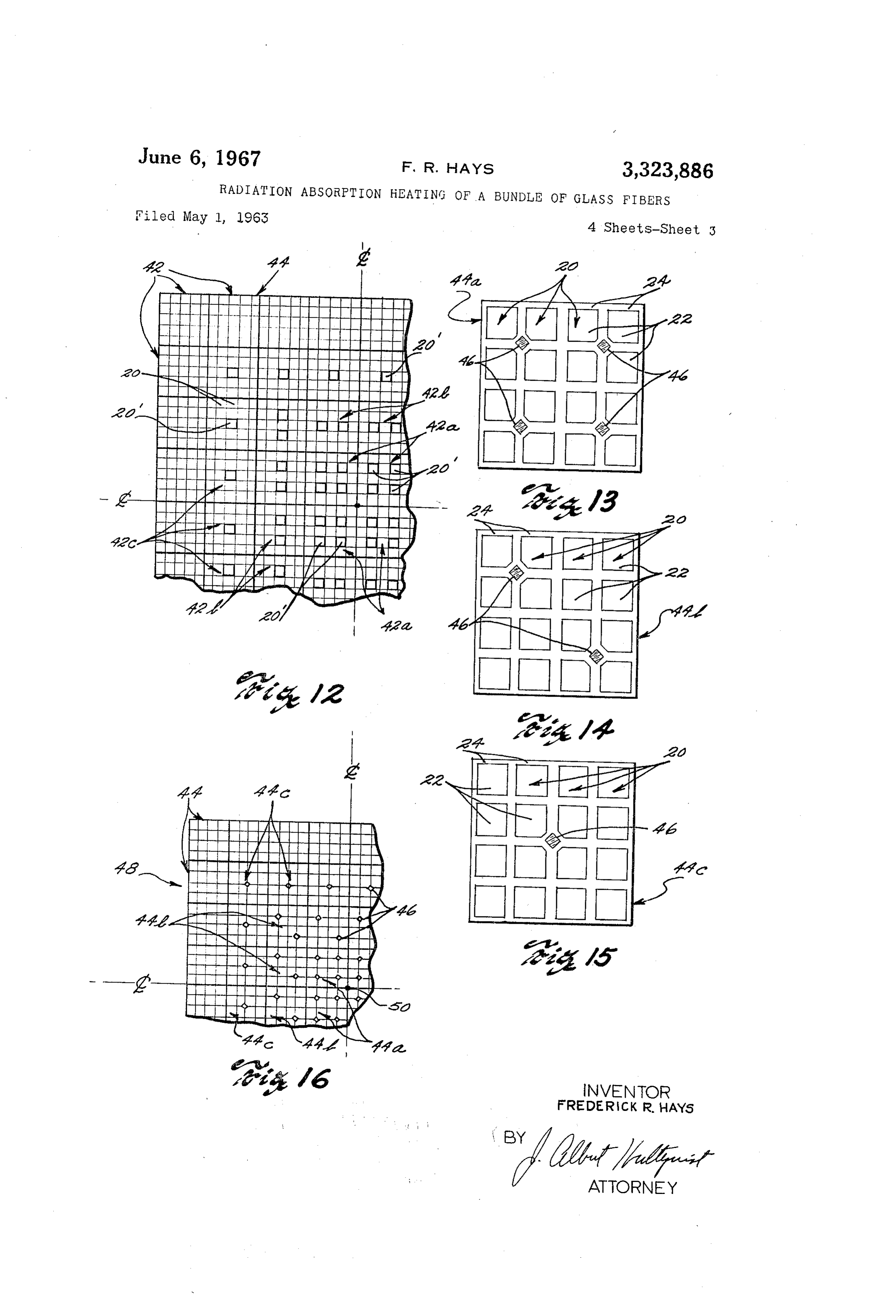
FIGS. 13, 14 and 15 are greatly enlarged end views of
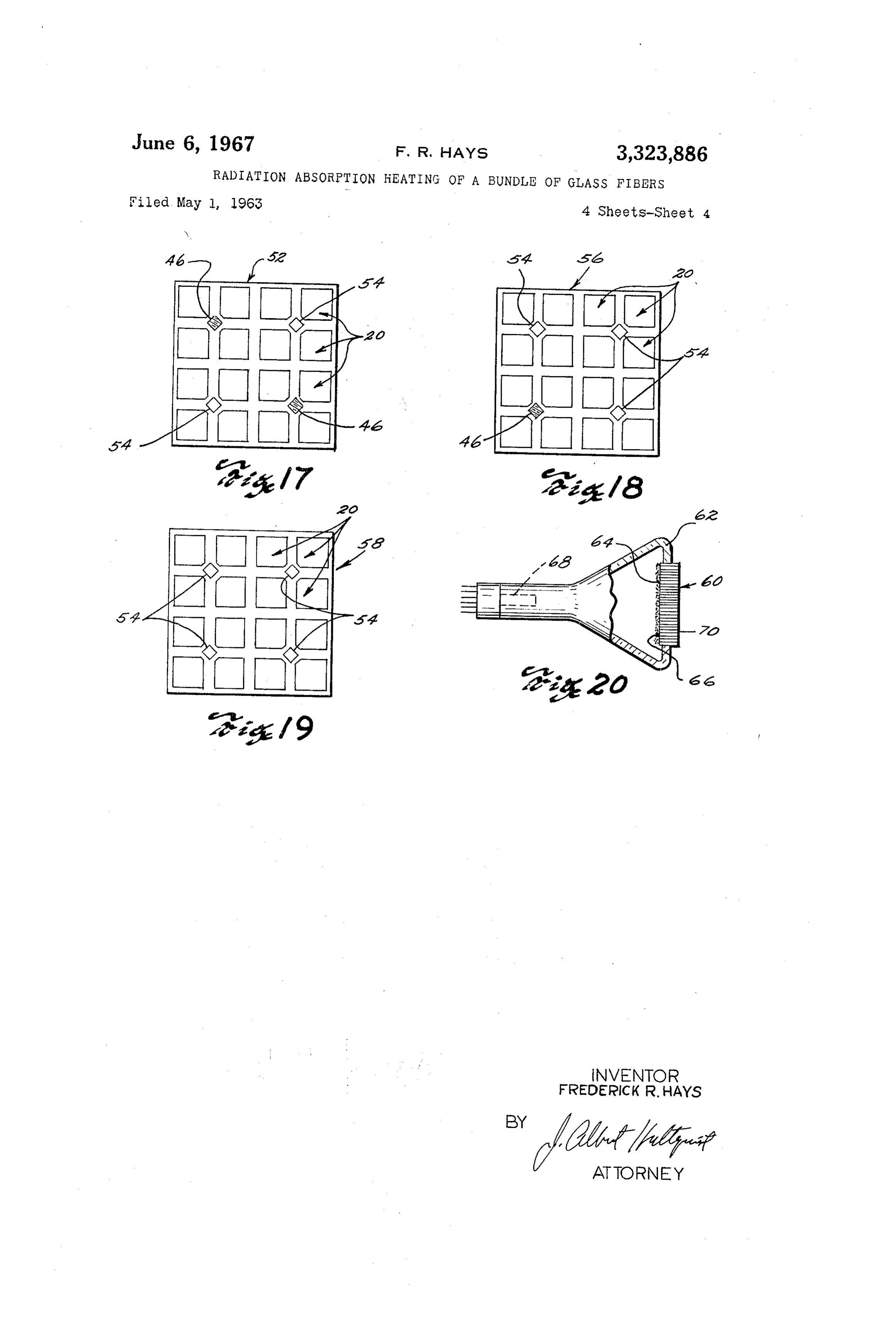
A further object is to provide for hermetically sealing a modified relatively large bundle of many heat softenable fiber ele 55 in forms of multifiber structures which can be used ments by fusion of said elements to each other substan the fabrication of devices of the invention; FIG. 16 is a fragmentary end view of an assembly of tially uniformly throughout all cross-sections of said bun multifiber dle and without causing appreciable distortion of said structures of the type illustrated in FIGS. 13-15; fiber elements. FIGS. 17, 18 and 19 are enlarged end views of further It is also an object of this invention to provide a novel modifications of multifiber structures; and and improved method of manufacturing a fiber optical 60 fiber FIG. 20 is a diagrammatic view illustrating use of a device consisting of a bundle of fibers wherein secure optical device constructed according to the present invention.
fusion of respective fibers therein can be accomplished in Referring to the drawings, (FIGS. 1 and 2) fiber 20 less time, with temperatures lower than are usually re comprises a core part 22 of light-transmitting material quired and with an assurance of security and uniformity 65 having a relatively high index of refraction and cladding of fusion throughout all depths of the bundle. 24 of light-transmitting material having a relatively low To attain the foregoing objects and others which may index of refraction. The fiber core and cladding parts appear from the following detailed description, the present form light-reflecting interface 26 therebetween. Fiber 20 invention contemplates the provision of fiber optical struc is adapted to receive light at one end as indicated by light tures which, when subjected to fusing temperatures in furnaces or the like, will absorb furnace radiation sub 70 ray than
L which is incident upon interface 26 at angle a greater the critical angle of reflection for the interface.
stantially equally at all depths therein so as to become According to the well-known principle of total internal
Page 6
reflection, this light will be repeatedly reflected in the bly of such fibers which is to be fused so that the com region of the interface 26 and thereby be conducted ponents are in increasing numbers and spaced progres through the fiber from one end to its opposite end. When, sively closer to each other as the center of the assembly for example, the fiber core part 22 is formed of flint glass is approached.
having an index of refraction of 1.75 and the fiber cladding 5 20'In (see one embodiment of the invention, a number of fibers
FIG. 5) are each provided with cladding 24 is formed of crown or soda lime glass or the like having an formed of relatively high infrared absorbing material. index of refraction of 1.52, light rays entering the fiber The index of refraction, expansion coefficient, viscosity at an angle b as great as approximately 60 will be sub stantially totally internally reflected adjacent interface 26 and spectral (visible light) transmission characteristics of and be conducted through core 22. The maximum light 0 the material of claddings 24' is chosen to match or be acceptance angle b is a function of the relative indices of Substantially similar to that of cladding 24 of fibers 20. refraction of the core and cladding materials as is well Accordingly, fibers 20' might, for example, embody core known. The fibers may be square in cross-section as parts 22 formed of optical flint glass having an index of shown, or may be round, hexagonal or of other desired refraction of approximately 1.75 with claddings 24' there configurations within the scope of the invention. Heat on of soda lime glass having an index of refraction of softenable transparent materials other than glass may be approximately 1.52 and which has been rendered rela used as long as the ratio of indices of refraction are such tively highly absorbent to infrared radiation by the addi as to provide total internal reflection over a useful range tion thereto of from .5 to 1 percent by weight of ferrous of angles. oxide.
Fiber optical devices to which principles of the present 20 withIn the assembling fibers which are to be fused in accordance principles of the invention, the assembly may be invention are particularly applicable are, in general, formed of fibers 2 and 20' as diagrammatically illus formed by assembling a multiplicity of relatively long trated in FIG. 7. Fibers 20', having relatively high infrared fibers such as 20 together in side-by-side relation and absorbing claddings thereon, as illustrated diagrammati Subjecting the resultant relatively long assembly thereof to heat sufficient to cause fusion of respective claddings 25 cally numbers by heavy outline in FIG. 7, are placed in greater adjacent center 40 of assembly 38 and in progres 24 to each other. sively lesser numbers with progessively wider spacings For purposes of illustration, one of various techniques which can be used to fabricate such relatively long fiber therebetween in radial directions away from center 40. optical assemblies is illustrated in FIGS. 3 and 4 wherein Thus, in heating bundle 38 in the manner illustrated in a multiplicity of fibers 20 are supported in a channel 30 FIG. 4, for example, furnace radiation will be absorbed in shaped block 28. Fibers 20 are stacked in parallel rela the usual manner by fibers 20 which have relatively low tion to each other in block 28. Block 28 is placed in a infrared absorbing properties. Infrared radiation from suitable oven or furnace 30. A weight 32 (see FIG. 4) or coils 34, however, will be more readily absorbed by other compressing means is fitted within block 28 on top claddings 24 of fibers 20. Fibers 20' will reradiate of fibers 20 to hold the same in intimate interfitting rela to their neighbors and thereby tend to equalize the tion with each other and to provide a slight compressing temperature distribution in bundle 33. This increased force on said fibers during fusion thereof. Block 28 and absorption compensates for the diminishing intensity of weight 32 are preferably formed of suitable refractory radiation toward the center of the assembly thereby pro materials which do not stick to the materials of fibers 20. viding for more uniform fusion throughout. Alternatively, a parting layer of material which does not 40 The number of fibers 20' interspersed within bundle 38 stick to the glass or to the material of block 28 may be and the spacing provided therebetween is determined by used. Mica may be used as such a parting layer. The the depth of bundle 38 so as to provide the bundle with assembly of fibers 20 is heated to fusing temperature by a gradually increasing or higher absorption coefficient means such as electrical heating coils 34 or the like as the center of the bundle is aproached. In this way, tem diagrammatically illustrated in FIG. 4. perature distribution throughout bundle 38 can be sub Radiation from heating coils 34 penetrates block 28 and stantially equalized to produce uniform fusion throughout. enters the assembly of fibers 20 to effect fusion of respec In another embodiment of the invention, fibers 20' of tive claddings thereof, and block 28 should be composed the type shown in FIG. 6 can be substituted for fibers of a material which is relatively transparent to radiation 20 shown in FIGS. 5 and 7. Fibers 20' are formed from coils 34 or which efficiently conducts heat from the 50 with core parts 22' of relatively high infrared absorbing exterior to the interior. material and claddings 24' of material which is rela Such an assembly of fibers may, alternatively, be sup tively nonabsorbent to infrared radiation. Fibers 20' can, ported for fusion within a tubular member of heat soften for example, embody core parts 22' formed of flint glass able glass material or the like rather than block 28 or held containing from approximately .5 to 1 percent by weight together with removable bindings or other suitable sup of ferrous oxide and having an index of refraction of ap porting means. Also, the assembly of fibers can be heated proximately 1.75. Claddings 24', in this instance, may be progressively from one end to the other thereof to effect formed of conventional crown or soda lime glass or the fusion of its fibers. like having an index of refraction of approximately 1.52. In fusing relatively large diameter and long fiber optical Ferrous oxide in core parts 22' will have substantially assemblies wherein heat must be introduced radially 60 no effect upon white light transmitted through fibers 20'. through the sides thereof, there is the tendency for the It should be understood that, for purposes of clarity, outermost fibers to become overheated and consequently fibers 20, 20' and 20' are illustrated in FIGS. 1, 2, 5,6 distorted while the innermost fibers are underheated and and 7 as being rather large and only a relatively few fibers not completely jointed together. This is the result of fur are bundled together to form assembly 38. Whereas in nace radiation being absorbed as it penetrates the assem practice, the fibers may be only a few microns in transverse bly of fibers. dimension and many thousands will be used. Since the heat generated at any depth in a bundle of Alternatively, where each light passage is required to fibers is proportional to the absorption coefficient times be as Small as 50 microns or less in diameter, fiber optical the intensity of radiation at that depth, a balance of heat asssemblies can be made up of multifiber structures. That absorbed at any depth can be achieved by increasing the 70 is, each fiber may contain a number of individual cores absorption coefficient of the bundle of fibers as its depth Surrounded by low refractive index material and all fused increases. together.
In accordance with this invention, components having a Such multifiber structures may be formed by grouping a higher absorption coefficient for infrared than that of Selected number of relatively large fibers together in ordinary optical fibers are interspersed within an assem 75 side-by-side relation and heating and drawing the group
Page 7
S. 6 thereof to a reduced cross-sectional size at which time re spective fibers of the group become fused to each other. structure have been shown. For purposes of illustration, multifiber In FIG. 8, a greatly enlarged end view of such a multi and thin 44a (FIG. 13) is shown as including four long relatively high infrared absorbing filaments 46 fiber structure 42 formed of a number of fibers 20 is il lustrated. Multifiber structure 42 is shown, for ease of while structure 44b (FIG. 14) includes two relatively high infrared absorbing filaments 46. Structure 44c (FIG. 15) illustration, as embodying only a relatively few fibers 20 includes which are relatively large in cross-section; it being under ment 46, aitsingle being relatively high infrared absorbing fila understood that much greater numbers stood that within the scope of this invention, a greater may be used to assure proper heat distribution in the number of fibers 20 per unit area might be provided in fusing process.
multifiber structure 42.
In a particular embodiment of this invention, multifiber O lime Infrared absorbing filaments 46 can be formed of soda structures are used in the fabrication of relatively long glass containing approximately 15% by weight of ferric oxide.
fused fiber optical devices similar to those illustrated in During the fabrication of respective multifiber struc FIGS. 3, 4 and 7. In this type of construction, the multi fiber structures are used as building blocks and are 15 tures 44a, 44b and 44c, filaments 46 are placed between respective fibers 20 which are initially grouped together, stacked, one upon the other, to form an assembly 44 such heated and drawn as described above with regard to fab as shown in FIG. 12. Assembly 44 can be subjected to ricating multifiber structures.
heat in the manner described with relation to assembly 38 In forming an assembly 48 of multifiber structures such so as to fuse respective multifiber structures together. as shown in FIGS. 13, 14 and 15 (see FIG. 16), a number In accordance with the principles of the invention, 20 of multifiber structures assembly 44 is provided with relatively high infrared ab assembly 48. A layer of44amultifiber are positioned centrally in structures 44b are sorbing components interspersed therein in such manner placed around structures 44a and another layer of multi as to increase the absorption coefficient of assembly 44 fiber structures 44c are positioned to surround structures as its depth increases. This is accomplished by providing 44b. Surrounding multifiber structures 44c are multifiber multifiber structures having different amounts of rela 25 tively high infrared absorbing components incorporated structures 44 formed entirely of fibers 20 without rela tively high infrared absorbing filaments therebetween. In therein. Such multifiber structures are assembled with those having greater amounts of relatively high infrared athisnumber construction, it can be seen that assembly 48 contains absorbing components nearer the center of assembly 44 46 which of relatively high infrared absorbing filaments progressively increase in number and are in and those having lesser amounts of relatively high infra 30 progressively closer spaced relation to each other as the red absorbing components positioned progressively toward center 50 of assembly 48 is approached. Thus, when as the outer boundaries of assembly 44. Sembly 48 is subjected to furnace radiation, as shown In FIGS. 9, 10 and 11 multifiber structures 42a, 42b in FIG. 4, filaments 46 will readily absorb infrared radia and 42c are illustrated as embodying relatively high infra tion from heating coils 34 and reradiate to neighboring red absorbing components. For purposes of illustration, fibers 20 So 48.as to equalize the temperature distribution multifiber structure 42a is shown to embody four such in assembly infrared absorbing components which, in accordance with In fused fiber optical devices of the type relating to this one aspect of the invention, comprise fibers 26’ having invention, light entering the core parts of fibers 20, 20 relatively high infrared absorbing claddings 24. Clad or 20' at one end thereof within their maximum light dings 24 of fibers 20” are cross-sectioned in FIGS. 9, 10 40 and 11 to distinguish the same from other parts of re acceptance angle b (FIG. 2) will be conducted through spective multifiber structures. Fibers 20, whose core and said core parts, to their respective opposite ends. How cladding parts are relatively nonabsorbent to infrared mum light ever, entering said fibers at angles outside the maxi light-acceptance angle b (see light ray c in FIG. 1) radiation make up the remainder of multifiber structure will be transmitted through interface 26 and escape from 42a. Multifiber structure 42b embodies two fibers 20' and 45 the particular fiber. In fused fiber optical devices, this multifiber structure 42c embodies a single fiber 20'; the light enters adjacent fibers as stray light and produces what remainder of structures 42b and 42c respectively being is termed as "cross-talk” between fibers. Such stray light made up of fibers 20.
In assembly 44 (see FIG. 12), a plurality of multifiber device andthe can reach output end face of the fused fiber optical produce an undesirable background of light structures 42a are positioned centrally therein, a layer of 50 which tends to wash-out or reduce contrast of light which multifiber structures 42b surround structures 42a and a is conducted through the core parts of the fibers. layer of multifiber structures 42c surround structures 42b. Such undesirable stray light can be reduced by placing The outer boundaries of assembly 44 are made up of filaments which are absorptive to visible light between multifiber structures 20. In this construction, it can be respective fibers of the device generally in the manner seen that assembly 44 contains a number of relatively 55 described hereinabove with relation to filaments 46. The high infrared absorbing components (illustrated by heavy Stray light absorbing filaments, outline) which progressively increase in number and are be interspersed throughout the however, device in would preferably substantially uni in progressively closer spaced relation to each other as formly spaced relation with each other rather than in pro the center of assembly 44 is approached. gressively increasing numbers toward the center of the It should be understood that fibers 20' such as shown 60 device as described with relation to filaments 46. in F.G. 6 can be substituted for fibers 20' in the construc In order to incorporate the use of stray light absorb tion of multifiber structures 42a, 42b or 42c. Furthermore, ing filaments along with the above described infrared ab more or less relatively high infrared absorbing compo sorbing filaments 46, the present invention contemplates ments (fibers 20” or 20') can be incorporated in respective the provision of multifiber structures such as are shown multifiber structures 42a, 42b or 42c. 65 in FIGS. 17, 18 and 19. Multifiber structure 52 (FIG. 17) In still another embodiment of this invention, infrared would embody two relatively high infrared absorbing fila absorbing filaments having relatively high absorption co ments 46 and two light absorbing filaments 54 which are efficients for infrared can be inserted between respective characterized to be relatively nonabsorbent to infrared fibers 20 of assemblies such as 38 (FIG. 7) or 44 (FIG. radiation but relatively highly absorbent to visible light. 12). In accordance with this aspect of the inventon, a 70 Filaments 54 might be formed of soda lime glass con number of multifiber structures similar to those illustrated taining approximately 20% manganese dioxide. Multi in FIGS. 8-11 can be formed of fibers 20 having long and fiber structure 56 (FIG. 18) would embody a single rela thin relatively high infrared absorbing filaments therein. tively high infrared absorbing filament 46 and three fila In FIGS. 13, 14 and 15 enlarged end views respectively ments 54. Multifiber structure 58 would embody four of three such multifiber structures 44a, 44b, and 44c 75 filaments 54 and no infrared absorbing filaments 46.
Page 8
In making an assembly such as 48 (FIG. 16), in accord cathode ray tube. In the embodiment of the invention ance with this aspect of the invention, a number of multi wherein visible light-absorbing filaments 54 are incor fiber structures 52 would replace structures 44b in FIG. porated, these filaments will absorb a substantial part of 16 and a number of multifiber structures 56 would replace 5 any Stray light from the original light image which is not conducted through specific fiber cores.
Structures 44c. Similarly, a number of multifiber struc This invention is not limited to the use of any particular tures 58 would replace structures 44. glasses or combination of glasses in the construction of In the resulting assembly, the combination of filaments fused fiber optical devices such as described. Although 46 and 54 would be interspersed throughout the assembly particular embodiment of the image-transfer devices and and each would function to absorb visible stray light. At the same time, infrared absorbing filaments 46, being in 10 methods of making the same according to this invention progressively increasing numbers and closer spaced rela ithavemust been described herein for the purpose of illustration, be understood that this invention includes all tion with each other in radial directions toward the center of the resultant assembly would function to absorb a sub modifications and equivalents thereof which fall within stantial amount of infrared radiation and distribute heat the Scope of the appended claims. uniformly throughout the assembly during fusion thereof I claim:
1. The method of forming a fused bundle of glass in accordance with the principles of this invention. fibers wherein the improvement comprises the steps of ar It should be understood that the structures of FIGS. 17, ranging in compact side-by-side relationship with each 18 and 19, are purely illustrative. Various different com other as a bundle a number of first glass fibers having binations in numbers, position and spacing of filaments 20 one coefficient of absorption for radiated heat energy and 46 and 54 might be provided in respective multifiber struc a number of second fibers at least a portion of each of tures. Also, fibers 20” or 20' such as shown in FIGS. which has a substantially higher coefficient of absorption 5-11 can be provided with a second outer cladding hav for said radiated heatenergy whereby said portions of said ing light absorbing properties similar to filaments 54 there second fibers will absorb greater amounts of radiated by to reduce undesirable stray light in structures Such as 25 heat energy applied externally to said bundle than will said shown in FIGS. 7, 12 and 16. first fibers and at least some of said greater amounts of In all embodiments of the invention shown and de scribed hereinabove, it can be seen that high energy in heat energy will become reradiated to respectively adja frared absorbing components are placed within fiber op cent first fibers, during said step of arranging said first tical assemblies to be fused in such manner that these and second fibers placing said second fibers among said components are in progressively increasing numbers and 30 first fibers in progressively increasing quantities and mutual proximity relative to the distance from the outer progressively closer spaced relation to each other in radial sides of said bundle towards its center Such that radiated directions toward a central axis through the particular heat energy absorbed by said second fibers and reradiated assembly. Thus, when such an assembly is subjected to furnace radiation, these infrared absorbing components therefrom supplements heat produced in said first fibers to produce substantially uniform heating throughout said will absorb and reradiate heat to neighboring fibers to bundle and, after such arranging is completed, applying provide a relatively fast and even distribution of heat to the exterior of said bundle radiant heat energy of throughout all cross-sections of the assembly so as to sufficient intensity to uniformly fuse all said fibers to effect uniform and secure fusion. With uniform tempera tures being distributed throughout such fiber optical as 40 gether.
2. The method as recited in claim 1 wherein Said semblies, lower than usual or minimum fusing tempera number of second fibers are each formed entirely of a tures can be used and less time than usual is required to material having a substantially higher coefficient of ab effect complete and secure fusion of the assemblies. Lower sorption for radiated heat energy than said first glass temperatures and less exposure time to fusing tempera tures reduce the tendency for distortion of fibers in an 45 fibers.
3. The method as recited in claim 1 wherein said Sec assembly thereof and obviate the wellknown adverse ond fibers each has a core and a relatively thin cladding effects of overfusion or overexposure to furnace radia of glass, said claddings respectively being said portions tion. thereof having said higher coefficient of absorption for Fused fiber optical devices of this type provided by this invention can be enployed as faceplates for cathode ray 50 radiated heat energy.
4. The method as recited in claim 1 wherein each of tubes or the like, for example, as shown in FIG. 20. Cath said second fibers has a core and a relatively thin cladding ode ray tubes, require face plate structures which are of glass, said cores being the portions thereof having vacuum tight and which, together with the tube envelope, said higher coefficient of absorption for radiated heat will hermetically seal the interior of the tube from outer atmospheres. energy.
In providing a cathode ray tube with a fiber optical 55 said5. second
The method as recited in claim 1 wherein each of fibers is of multifiber construction at least face plate, a relatively long fiber optical device such as is a portion of which has said higher coefficient of absorp formed in accordance with this invention can be cut trans axially and parallel to an end face thereof to form a plate tion for radiated heat energy.
like element 60 (see FIG. 20) of desired thickness. Ele 60 References Cited ment 60, being vacuum tight, is edge sealed in vacuum tight relation to the tube envelope 62 in conventional man UNITED STATES PATENTS ner. Plate-like element 60 is provided with phosphors 64 2,440,187 4/1948 Silverberg. upon the image-receiving, input end face 66 thereof.
Electron gun 68 of the cathode ray tube can then direct 65 OTHER REFERENCES an electron beam as controlled by conventional tube de General Electric Review: vol. 44 No. 3. March 1941 flecting means (not shown) for exciting phosphors 64 to form a light image upon face 66 in conventional manner. pp. 169-176 entitled "Infrared Production and Transmis The core parts of fibers embodied in plate-like element sion Reflection and Measurement,” by L. R. Koller. 60 then receive light from respective segments of this 70 DONALL H. SYLVESTER, Primary Examiner. light image and conduct a large part of said light through the cores for reproducing the light image in mosaic form F. W. MIGA, Assistant Examiner, upon face 70 of plate-like element 60 exteriorly of the
Provenance
- Collection
- Cited prior art
- Original PDF
- patentimages.storage.googleapis.com →
- Filed
- 1963-05-01
- Pages
- 8
- Method
- pdftotext (the PDF's own text layer) + pdftoppm 300dpi page scans
- Source
- Google Patents bibliographic record
- Granted
- 1967-06-06
- Inventors
- Frederick R Hays; American Optical Corp
- Transcribed from
- patentimages.storage.googleapis.com →