patent · US5295818A
Control unit for burner assembly
22 March 1994
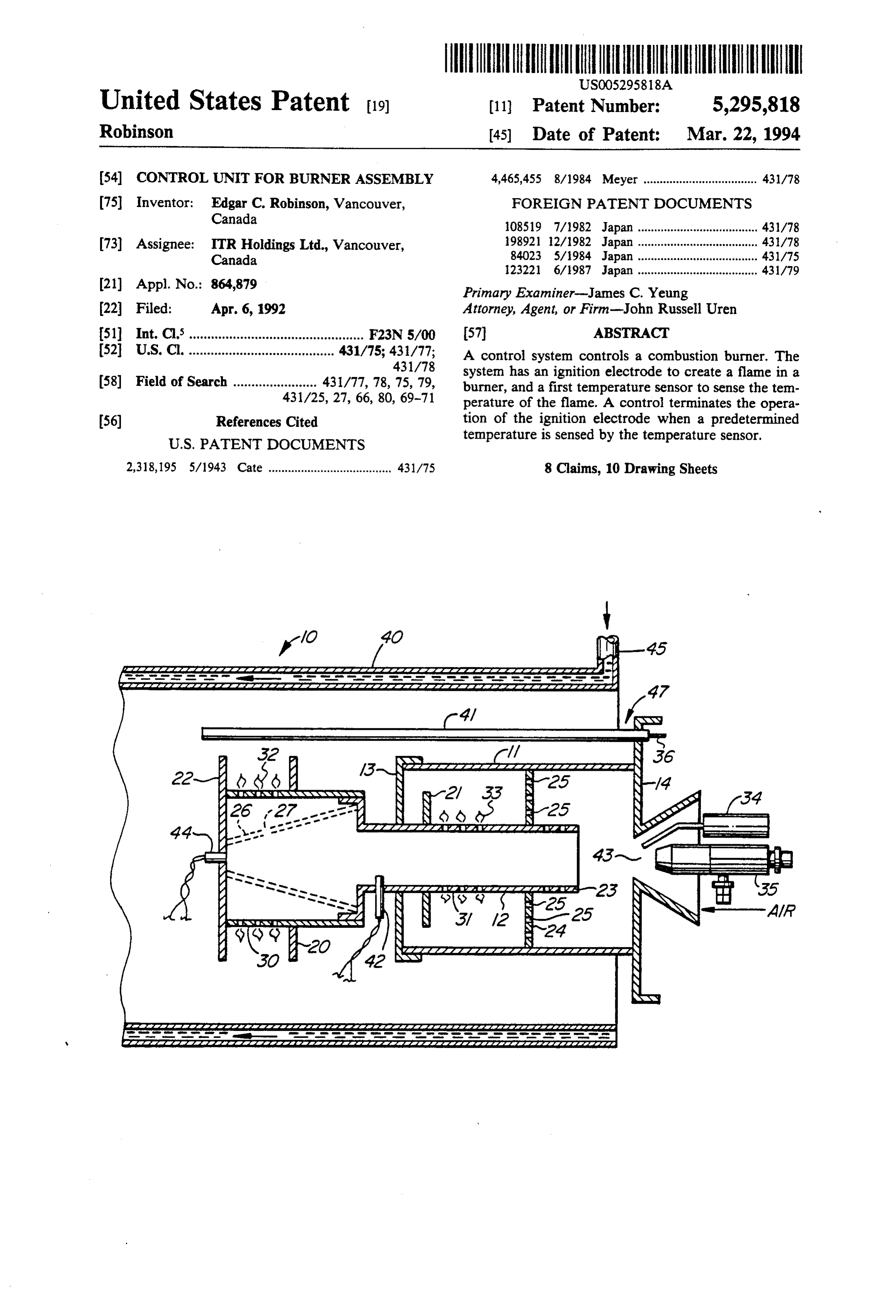
Page 1 — bibliographic record
United States Patent 19) (11) Patent Number: 5,295,818 Robinson 45) Date of Patent: Mar. 22, 1994 (54) CONTROL UNIT FOR BURNER ASSEMBLY 4,465,455 8/1984 Meyer ................................... 43/78 (75) Inventor: Edgar C. Robinson, Vancouver, FOREIGN PATENT DOCUMENTS Canada 108519 7/1982 Japan ..................................... 431/78 73) Assignee: ITR Holdings Ltd., Vancouver, 198921 12/1982 Japan .... 431/78 Canada 84023 5/1984 Japan .... . 431/75 123221 6/1987 Japan ..................................... 431/79 (21) Appl. No.: 864,879 Primary Examiner-James C. Yeung (22 Filed: Apr. 6, 1992 Attorney, Agent, or Firm-John Russell Uren 51) Int. Cl................................................. F23N 5/00 57 ABSTRACT (52) U.S.C. ........................................ 431/75; 431/77; A control system controls a combustion burner. The 431/78 system has an ignition electrode to create a flame in a 58) Field of Search ....................... 431/77, 78, 75,79, burner, and a first temperature sensor to sense the ten 431/25, 27, 66, 80, 69-71 perature of the flame. A control terminates the opera (56) References Cited tion of the ignition electrode when a predetermined
temperature is sensed by the temperature sensor.
2,318,195 5/1943 Cate ...................................... 431/75 8 Claims, 10 Drawing Sheets
Nzzzzzzzzzzzzzzzzzzzzzzzzz
avaaaaaaaaaaaaaayavaaaaaaayaaaaaaaaaaaaaaaaaaaaaaaaaaaaaaaaaaaaaaaaaaaaaaaaaaaa
Page 2
Drawing sheet — no readable text.
Page 3
Drawing sheet — no readable text.
Page 4
Drawing sheet — no readable text.
Page 5
Drawing sheet — no readable text.
Page 6
Drawing sheet — no readable text.
Page 7
Drawing sheet — no readable text.
Page 8
Drawing sheet — no readable text.
Page 9
Drawing sheet — no readable text.
Page 10
Drawing sheet — no readable text.
Page 11
Drawing sheet — no readable text.
Page 12
1 2 M said burner tube, at least one flame grid for said burner
CONTROL UNIT FOR BURNER ASSEMBLY tube, one of said flame grids being located adjacent said burner cap within said burner jacket and a flame reten
INTRODUCTION tion barrier extending outwardly from said burner tube This invention relates to a burner assembly for a 5 and being located between said flame grid and said heater and, more particularly, to a blue flame burner burner cap.
assembly which is of cylindrical configuration and According to yet a further aspect of the invention, which is operable with a variety of fuels. there is provided a control system for a combustion
BACKGROUND OF THE INVENTION
burner comprising ignition electrode means operable to 10 create a flame in said combustion burner, first tempera
It is desirable in a burner to have as high an efficiency ture sensing means to sense the temperature of said as possible since, traditionally, burner efficiency is rela combustion burner and first control means to terminate tively low. In burners such as the burner shown U.S. operation of said ignition electrode when a predeter Pat. No. Re. No. 28,679, naming the same inventor, a mined temperature is sensed by said temperature sens horizontally positioned grid burner is utilised. The use 15 ing means.
of such a burner in certain applications has an efficiency According to yet a further aspect of the invention, that is relatively low. Further, such a burner configura there is provided a control system comprising a flame tion is inoperable for practical purposes where a hori rod producing a first signal voltage upon ignition of said zontal rather than a vertical configuration for the heat 20 control system, means to provide comparison between exchanger is required. said signal voltage and upper and lower reference volt Yet another disadvantage with existing burner assem ages, said signal voltage being within the range of said blies is that unnecessary electrical power can be con upper and lower reference voltages by a first predeter sumed in ignition. Ignition utilises electrical discharge mined amount, a burner operable to reduce said first from the battery or batteries connected to the ignition signal voltage as the operating temperature of said electrode and the discharge occurs until the tempera 25 burner increases, means to reduce said upper and lower ture for self sustained combustion is reached. In previ signal reference voltages as said first signal voltage is ous heaters, ignition was independent of the tempera reduced, said first reference voltage being operable to ture of the burner and operated for a predetermined stay within said range of said upper and lower signal time period. Since the temperature for self sustained reference voltages as said first reference voltage is re combustion may be reached much more quickly when 30 duced and means to terminate operation of said burner the burner is warm, the additional time for electrode if said first signal voltage changes such that said first operation was frequently unnecessary and the electrical signal current expended from the battery is wasted. A further lower voltage reference is outside of the range of said upper and voltages.
problem with the aforementioned timed electrode dis charge is that the burner can become dangerously hot. 35 BRIEF DESCRIPTION OF THE SEVERAL Yet a further disadvantage of previous burners is that VIEWS OF THE DRAWINGS there is no means to measure whether the flame in the burner is luminous or not. It is desirable in combustion A specific embodiment of the invention will now be burners to keep the flame blue. This is so since the car described, by way of example only, with the use of drawings in which:
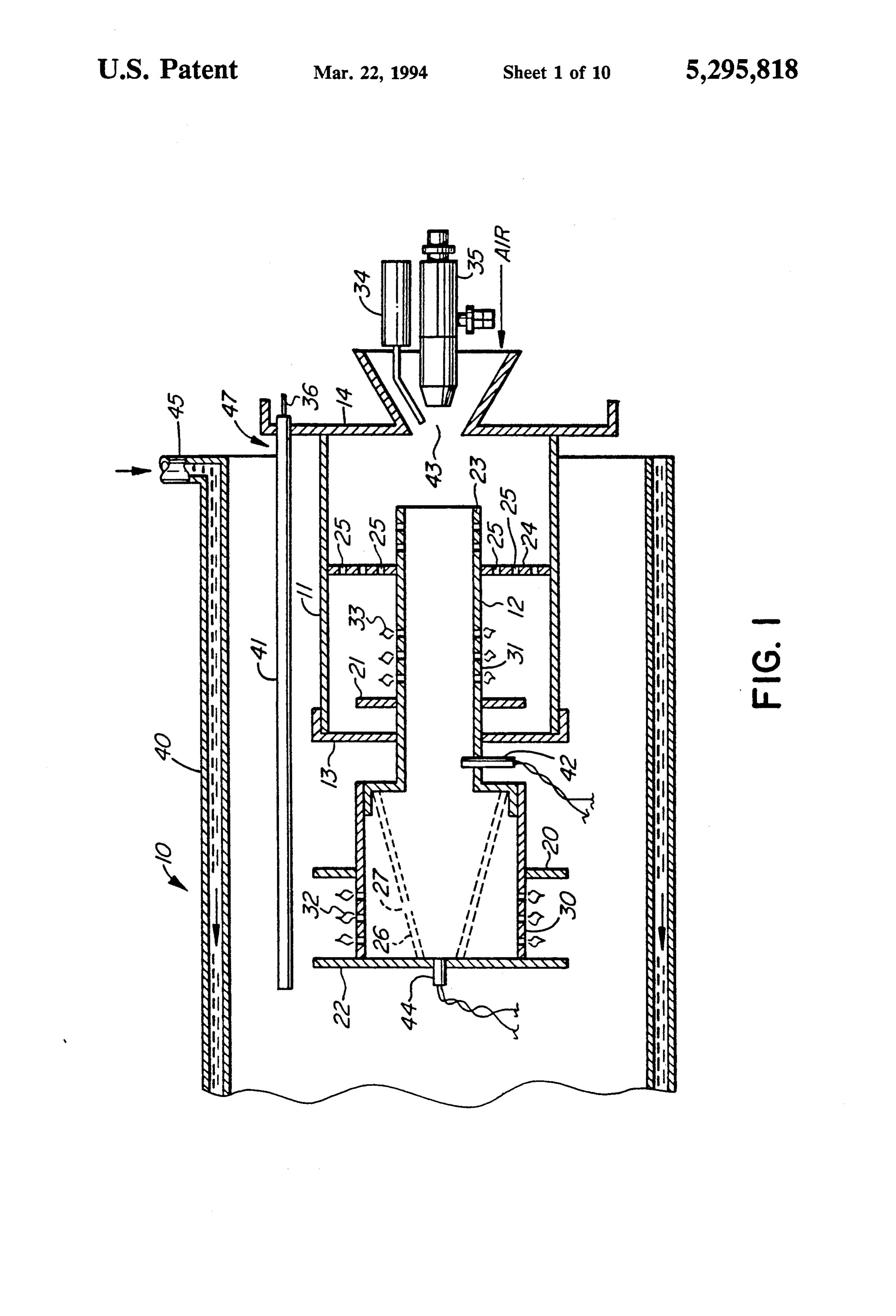
bon material created from a blue flame will be minimal or non-existent. If the flame turns luminous, carbon is FIG. 1 is a side sectional view of a burner assembly created which reduces the efficiency of the burner. according to the invention being mounted within a Yet a further disadvantage of previous burners and, in water jacket;
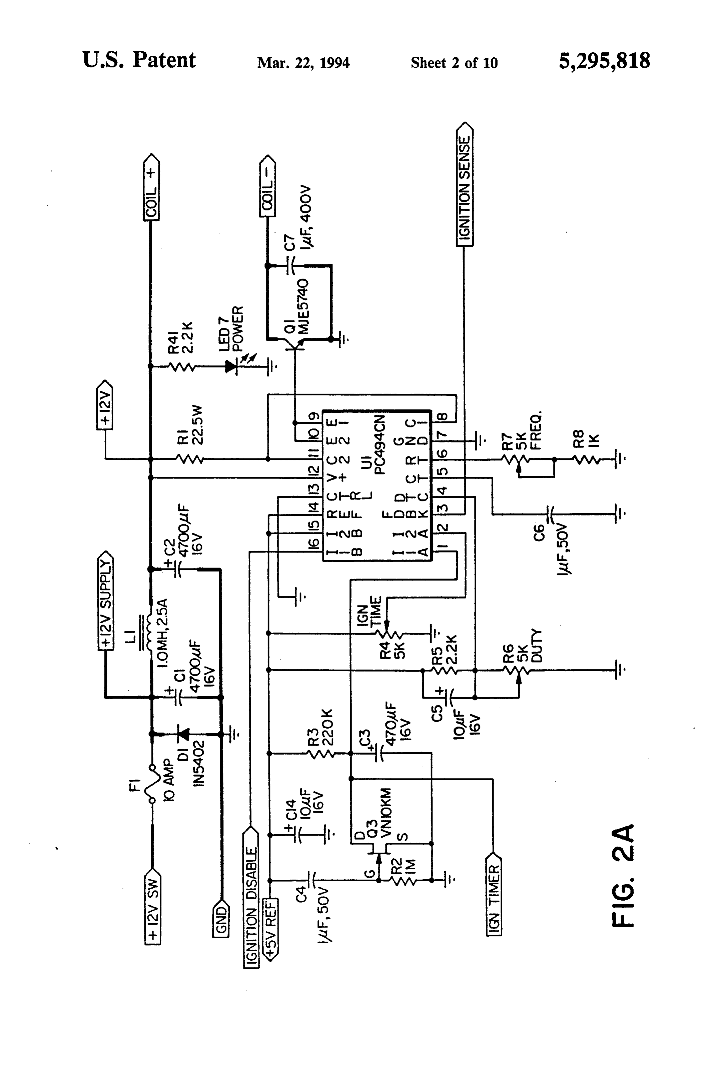
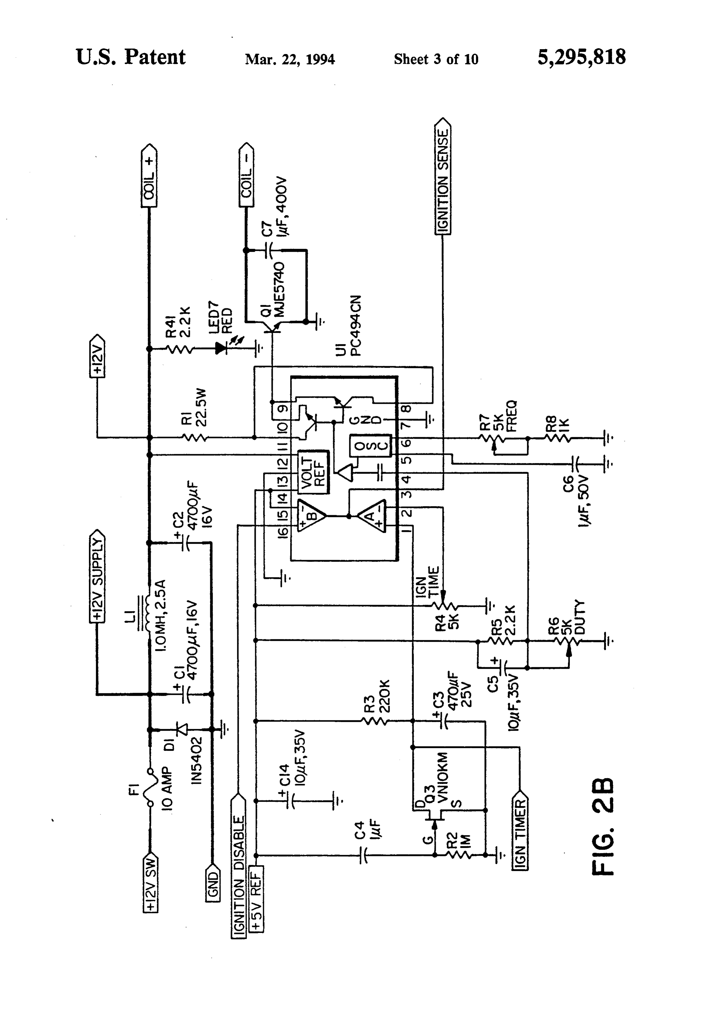
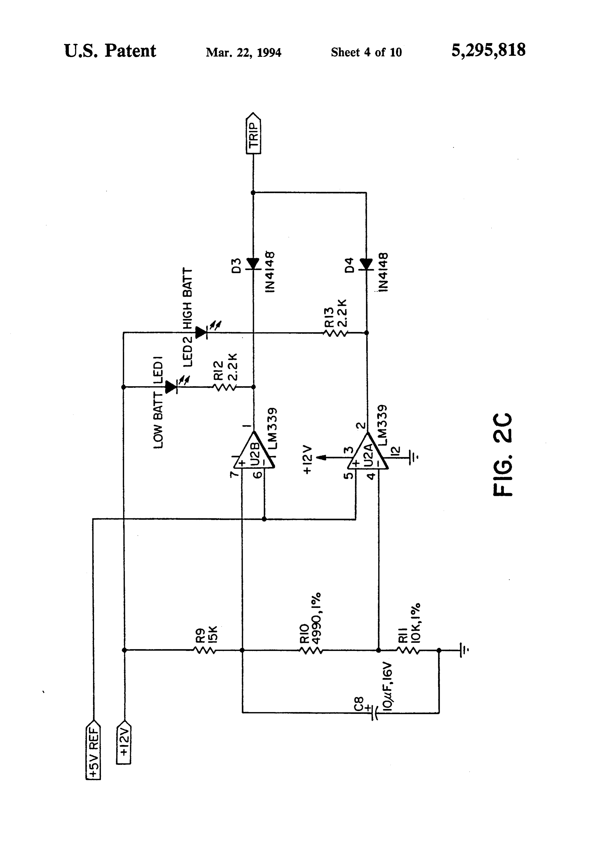
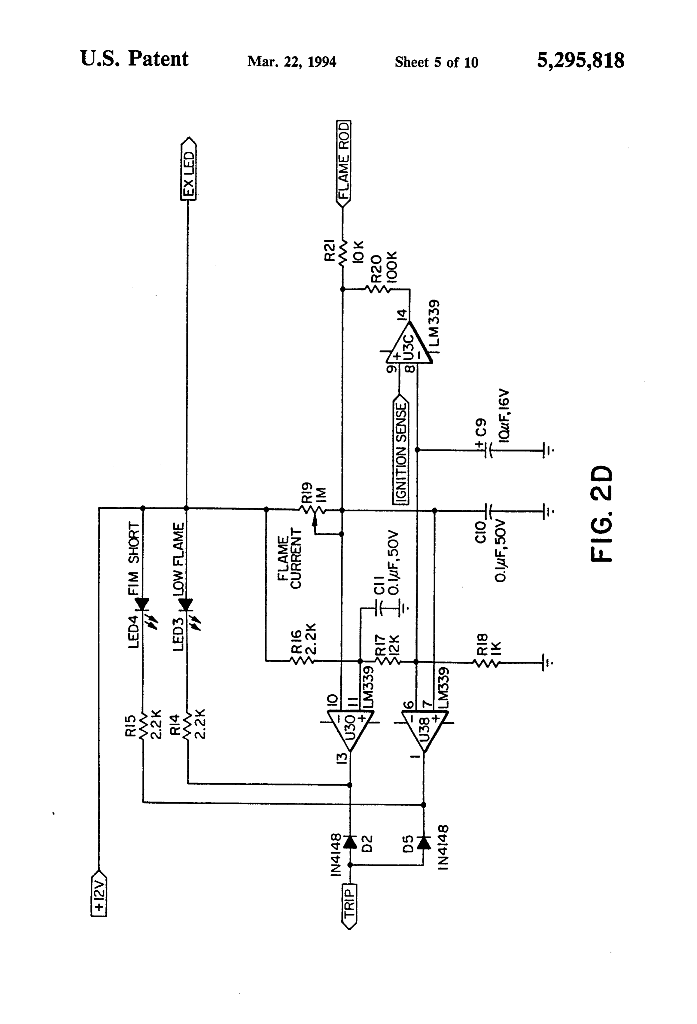
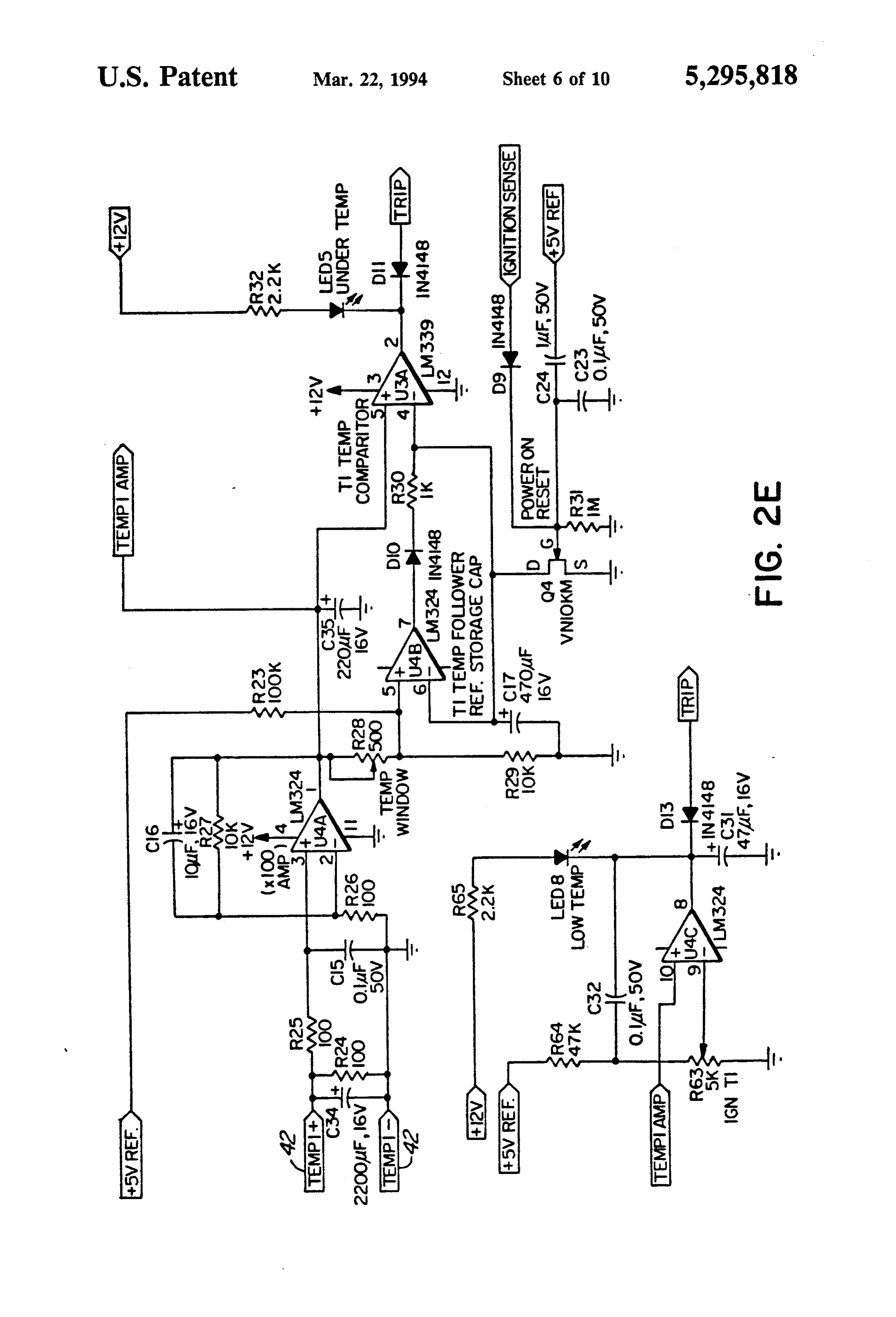
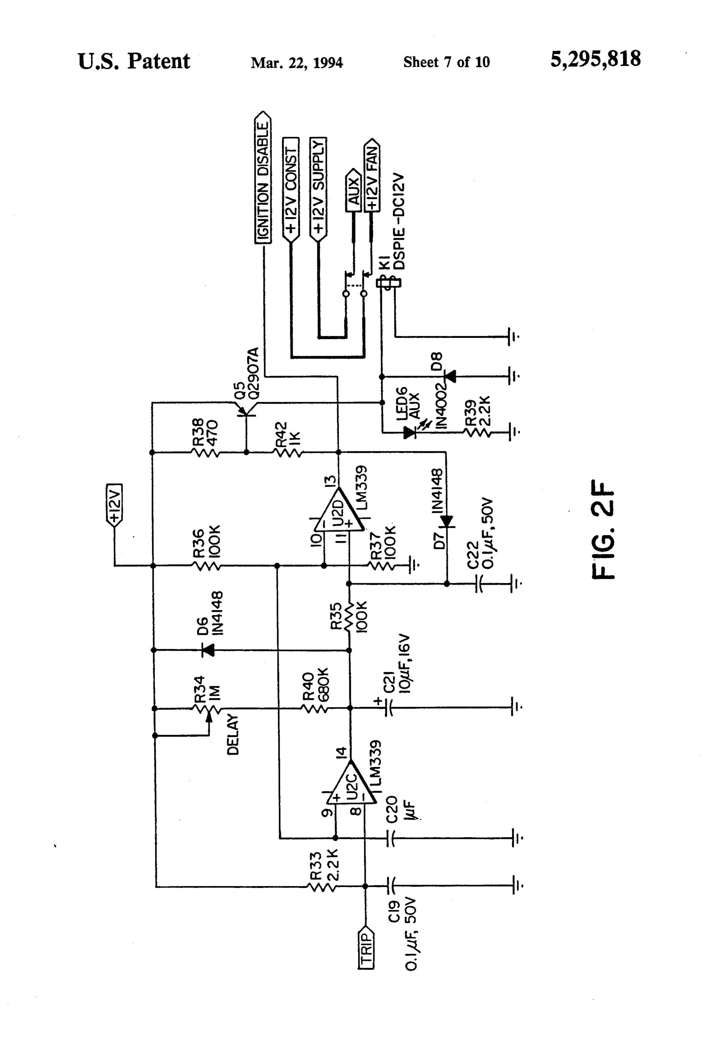
particular, the burner disclosed and illustrated in the FIGS. 2A through 2H are schematic diagrams of the above-identified U.S. Reissue patent, is that the flame 45 electronic control circuit which controls the operation illustrated just inside the end wall tended to be unstable of the burner assembly; and under certain conditions, particularly where the air FIG. 3 is a schematic diagram of a further embodi flow was high. If a burner flame is not stable, it can lift ment of the control system according to the invention. off the burner grid and, thereby, reduce the efficiency DESCRIPTION OF SPECIFIC EMBODIMENT of the burner. Yet a further disadvantage of heaters 50 wherein the flame lifts off the burner grid is that carbon Reference is now made to the drawings and, in partic monoxide can be produced which is harmful and possi ular, to FIG. 1 where a burner assembly is generally bly dangerous. illustrated at 10. It comprises a burner jacket 11, an
SUMMARY OF THE INVENTION
inner burner tube 12, a burner cap 13, all of which is 55 attached to a wall 14 on which the burner assembly 10
According to one aspect of the invention, there is is mounted.
provided a burner assembly comprising a cylindrical A water jacket 40 is located coaxial with and sur burner tube having a longitudinal axis, at least one flame rounds the burner tube 12 and the burner jacket 11. grid for said burner tube, said flame grid extending Water circulates under pressure through the water around the circumference of said burner tube, a nozzle 60 jacket 40 and enters the water jacket 40 at inlet 45. assembly to supply a fuel and air mixture and an ignition Three flame retention barriers 20, 21, 22 are con electrode to increase the temperature of said burner nected to the circumference of the burner tube 12, bar assembly to a self-sustaining combustion value and to rier 22 being solid, connected to the end of the burner ignite said fuel and air mixture. tube 12 and extend outwardly therefrom. Barrier 20 is According to a further aspect of the invention, there 65 also solid with the exception of a hole which allows the is provided a burner assembly comprising a cylindrical burner tube 12 to pass therethrough and is connected to burner tube, a burner jacket surrounds said burner tube, the burner tube 12 between the burner cap 13 and the a burner cap extending between said burner jacket and end barrier 22. Barrier 21 is also solid with the exception
Page 13
of a hole allowing the burner tube 12 to pass there a power supply circuit 52, a timer circuit 54, and an through and is connected to the burner tube 12 between integrated circuit 56.
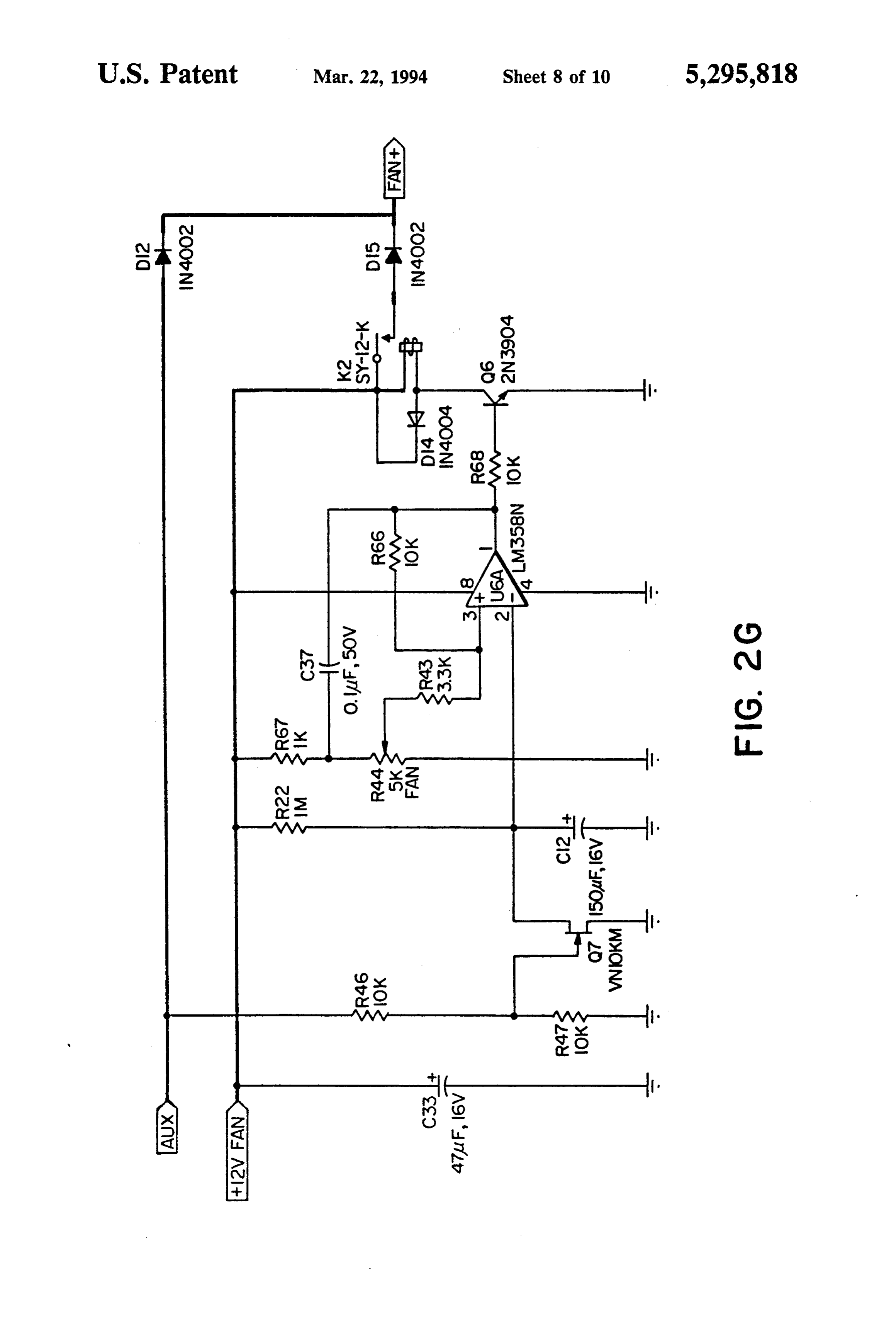
the burner cap 13 and the inner end 23 of the burner FIG. 2B provides a more detailed view of the inte tube 12. grated circuit 56. The integrated circuit 56 comprises A first flame arrestor plate 24 is connected between comparator circuits 58 and 60, a voltage reference cir the burner tube 12 and the jacket 11. Holes 25 extend cuit 62, and an oscillator circuit 64. axially through the flame arrestor plate 24. A second With regard to FIG. 2C, a battery level circuit is flame arrestor plate 26 is mounted within the burner indicated generally at 66. The battery level circuit 66 tube 12. It includes a light off hole 27. A corresponding comprises a voltage divider network 68 and comparator light off hole 28 is also present in the flame grid 30. The 10 circuits 70 and 72.
purpose of the light off holes 27, 28 is to allow the With regard to FIG. 2D, a flame rod sensor circuit is ignition flame to light the fuel on the flame grid 30. indicated generally at 74. The flame rod sensor circuit The burner tube 12 is cylindrical in configuration and 74 comprises comparator circuits 76, 78, and 80, and a has two flame grids 30, 31 which are perforate and voltage divider network 82.
extend around the circumference of the burner tube 12 15 With regard to FIG. 2E, a temperature window and in the locations indicated. The grids 30, 31 allow the level circuit is indicated generally at 84. The tempera release of fuel vapour which ignites and burns on the ture window and level circuit 84 comprises a differen outside of the flame grids 30, 31. The flame 32, 33 on tial amplifier circuit 86, a comparator circuit 88, a fol grids 30, 31, respectively, burns blue and non-luminous. lower circuit 90, a comparator 92, and a temperature An ignition electrode 34 and a fuel nozzle assembly 20 window reset circuit 94.
35 are each mounted on the side of wall 14 opposed With regard to FIG. 2F, a trip circuit is indicated from the burner tube 12. The ignition electrode 34 is generally at 96. The trip circuit 96 comprises compara connected to a source of power such as a battery and tor circuits 98 and 100, a transistor circuit 102, and a under the control of a circuit, is used to ignite the fuel relay circuit 104.
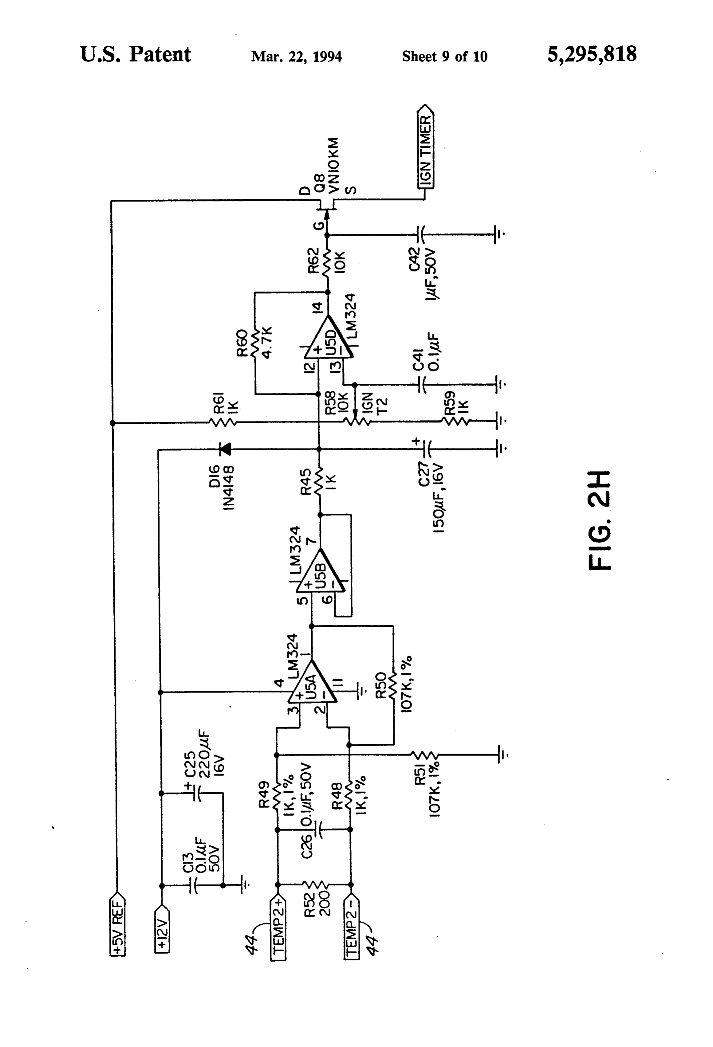
prior to the burner assembly reaching its self-sustaining 25 With regard to FIG. 2G, a fan delay circuit is indi combustion temperature as will be described in detail cated generally at 106. The fan delay circuit 106 com hereafter. The fuel nozzle assembly 35 is used to vapor prises a transistor circuit 108, a differential amplifier ize the fuel used to sustain the combustion also as de circuit 110, a transistor circuit 112, and a relay circuit scribed in greater detail hereafter. 114.
The cylindrical water jacket 40 carries the water to 30 With regard to FIG. 2H, an ignition thermocouple be heated by the burner assembly 10. The water circu circuit is indicated generally at 116. The ignition ther lating through the jacket 40 exits the jacket 40 following mocouple circuit 116 comprises differential amplifier heating and is routed to the area where the heat is re circuits 118, 120, and 122, a voltage divider network quired to be radiated. 124, and a transistor circuit 126. Two thermocouples 42, 44 are utilised. Thermo 35 OPERATION couple 42 is mounted through burner tube 12 at the position indicated just outside of the burner cap 13 and In operation and in order to reach a temperature before the location of the flame retention barrier 21. required for self sustaining combustion, the ignition Thermocouple 44 is mounted directly to the flame re electrode 34 is activated with power from the battery or tention barrier 22. Each thermocouple 42, 44 is sensitive other power source (not illustrated). Fuel enters the to the temperature in its area and each of the thermo nozzle assembly 35 where it is vaporized and expelled couples 42, 44 has its resistance monitored by the con through the orifice 43 of the nozzle assembly 35. Air trol circuit illustrated in FIGS. 2A-2H for the burner enters the burner assembly around the nozzle assembly assembly 10. Thermocouple 42 senses the heat gener 35.
ated by the flame which is created by operation of the 45 The discharge from the ignition electrode 34 is used ignition electrode 34. to ignite the fuel and air mixture from the orifice 43 to Thermocouple 44 monitors the temperature at the create a long tongue flame extending into and substan burner cap 22 up to 1000 deg. F. Once that temperature tially the length of burner tube 12 which heats the is reached, the thermocouple 44 terminates the opera burner assembly 10 and thermocouples 42, 44. Assum tion of the ignition electrode 34 through the control 50 ing the fuel air mixture is correct, when the thermo circuit as is also described in more detail hereafter. couple 44 reaches a temperature of approximately 1000 The flame rectification system generally indicated at degrees Fahrenheit, the thermocouple 44 will act on the 47 comprises a conductive rod 41 which is mounted in control circuit as illustrated in FIG. 2H which will the wall 14. A contact 36 is connected to the end of terminate the operation of the ignition electrode 34. conductive rod 41 for connection to a source of electri 55 This temperature is sufficient for self-sustaining con cal power. The conductive rod 41 allows a current to bustion of the fuel and the flame 32 will appear on the pass through the rod 41 and the flame 32 to ground. In grid 30.
the absence of a flame, no circuit is established and the The use of thermocouple 44 to sense burner tempera control circuit will activate fuel termination as de ture of 1000 deg. F. has a further advantage in the cir scribed in more detail hereafter. 60 cuit and that is to minimize operation of the ignition A thermostat (not shown) is connected to the outlet electrode 34 and, therefore, power use from a battery (not shown) of the water jacket 40. It monitors the for example, if the burner assembly 10 is warm. For temperature of the water within the water jacket 40 and example, should the burner assembly 10 be temporarily is operable through the control circuit to commence the shut down for only a short period, the time taken for the operation of the burner assembly 10 when the water 65 ignition electrode 34 to make the burner assembly 10 temperature reaches a certain level. reach a temperature of 1000 deg. F will clearly be con With regard to FIG. 2A, an ignition circuit is indi siderably shorter than if the burner assembly 10 is start cated generally at 50. The ignition circuit 50 comprises ing from a cold, long shutdown state. Thus, only the
Page 14
most efficient use of battery power is made to reach the and will radiate heat outwardly toward the jacket 40 in self sustaining temperature value required for continued order to heat the water being circulated therethrough. operation of the burner assembly 10. The flame retention barriers 20, 21, 22 act to keep the Thermocouple 42 senses the presence of the flame blue flames 32, 33 on the respective flame grids 30, 31 of within the burner tube 12 after operation of the ignition the burner tube 12 which allows for a more efficient electrode 34 is initiated. If no heat (and, therefore, combustion of the fuel and further allows the flame to burn well with a higher velocity forced air draft which flame) is present, due to the absence of fuel or for other operating reasons, the thermocouple 42 will act through may be natural or induced by a fan, for example. the control circuit of FIG. 2E to shut down the burner A further control by way of a thermostat (not shown) assembly within two (2) to four (4) seconds. Likewise, O monitors the temperature of the water in the water should the temperature sensed by thermocouple 42 jacket 40 during operation. Should the temperature of decrease such as would be the case if the flame initially the water in jacket 40 exceed 185 deg. F., the burner was present but, thereafter, it slowed down because of assembly 10 will shut down, When the temperature lack of fuel for example, the thermocouple 42 will like reaches 160 deg. F., the burner assembly 10 will again wise terminate the operation of the burner assembly. 15 commence operation in accordance with the operation A certain temperature window is also created by the of the ignition electrode 34 and subsequent elements as control circuit in association with thermocouple 42. described earlier.
The temperature window is a change in voltage from Dimensions of a typical burner assembly 10 accord the thermocouple of approximately one (1) mv which ing to the invention include an outside diameter for the translates into approximately 50 to 100 deg. F. This 20 burner tube 12 of approximately linches and a diame window follows the temperature rise of the thermo ter of the flame retention barriers 20, 22 of approxi couple 42 and, so long as the temperature sensed by the mately 3 inches. The length of the burner tube 12 is thermocouple 42 falls within this temperature window, approximately 6 inches and the diameter of flame reten the burner assembly 10 will continue operation. Other tion barrier 21 is approximately 2 inches. The outside wise, the control circuit will shut down the burner 25 diameter of the burner jacket 11 is approximately 3: assembly operation. inches and the length of the burner jacket 11 from the Assuming the burner assembly 10 is operating cor wall 14 is approximately 5 inches.
rectly and thermocouple 44 senses the required 1000 With such dimensions, it has been found that the deg. F. temperature, thermocouple 42 is then disarmed burner assembly 10 will produce approximately 35000 from the control circuit and the temperature window is 30 BTU/hour of operation. It has been found that with this reset. heat output, approximately 30 gallons of water/hour A third control is the timer circuit 54 illustrated in the will be heated with approximately a 100 deg. F. temper control circuit of FIGS. 2A and 2B. Timer 54, the time ature rise.
period of which is adjustable through potentiometer R4 The electrical system used to power the burner as (FIG. 2B), overrides both thermocouples 42, 44. The 35 sembly is a 12 volt system but it may be operated from timer 54 commences operation upon initial operation of a 24 or 110 volt system as well with the proper choice the ignition electrode 34 and acts, if the ignition elec of components in the control system. trode 34 is not terminated within an adjustable time With regard now to FIGS. 2A through 2H, a more period typically ranging from thirty (30) to one hundred detailed operation of the electronic circuitry will be twenty (120) seconds, the timer 54 will terminate shuts presented.
down the operation of the ignition electrode 34. If the With regard to FIGS. 2A and 2B, the power supply electrode 34 is shut down and the fame rectification circuit 52 provides d.c. power to both the electronic system senses a flame 32 on grid 30, as will be described and the electric portions of the circuitry. The timer in greater detail below, the fuel will continue to flow as circuit 54, as adjusted by R4, determines the maximum the burner assembly is deemed to be operating cor 45 length of time that the ignition electrode 34 will be rectly. The timer 54 is, therefore, a fail-safe device turned on. The integrated circuit 56 performs three which provides for system shutdown if there is no flame functions. First, it provides a +5 v reference voltage 32 on the grid 30 after a predetermined time period. using circuit 62. Second, using oscillator circuit 64, it The flame rectification system 47 which consists of provides a variable duty cycle oscillating signal to con the conductive rod 41 mounted in wall 14 with the 50 trol the ignition electrode 34. Finally, it provides a connection 36 to a power source (not shown) takes over feedback signal IGNITION SENSE to the ignition system control as soon as thermocouple 44 reaches a sensor circuitry (see FIGS. 2D and 2E) based upon the temperature of 1000 deg. F. and the ignition circuit is state of the timer circuit 54, the IGNITION DISABLE therefore shut down. If a flame is sensed and continues signal (see FIG. 2F), and the IGNITION TIMER sig to be sensed thereafter, fuel will continue to flow. If a 55 nal (see FIG. 2H).
flame suddenly disappears or if the flame becomes lumi The IGNITION SENSE signal means that there is nous, the flame rectification system 47 through the reason to turn off the ignition electrode 34. The IGNI control circuit illustrated in FIG. 2D will terminate fuel TION SENSE signal will below when the timer circuit flow to the burner assembly 10. This is a safety as well 54 is initialized. As time passes, the voltage across ca as an efficiency measure since fuel flow would other pacitor C3 will exceed the voltage tapped at potentiom wise continue to flow and, upon shutdown and eventual eter R4 and the output of the comparator 58 (IGNI subsequent reignition, excess fuel within the burner TION SENSE) will go high. The IGNITION SENSE assembly 10 which had been previously provided signal will also go high if the comparator 58 detects the would be required to be burned off. IGNITION TIMER signal or the comparator 60 de During the operation of the burner assembly 10, a 65 tects the IGNITION DISABLE signal.
blue flame 32, 33 will emanate from the flame grids 32, With regard to FIG. 2C, the voltage of the source 31, respectively. The blue flame 32, 33 will extend com battery (not shown) is divided across voltage divider 68. pletely around the circumference of the burner tube 12 The comparator circuits 70 and 72 both naturally out
Page 15
put a digital high signal. If the voltage of the source amplified and buffered by differential amplifiers 118 and battery (not shown) falls below a tolerance determined 120. The amplified signal is compared with an absolute by the resistors used in the divider network 68, then the reference using voltage divider 124 and differential output of the comparator 70 goes low, LED1 indicates amplifier 122. When the thermocouple temperature a LOW BATT condition, and a TRIP signal is initiated. 5 exceeds the reference signal, the differential amplifier If the voltage of the source battery (not shown) rises 122 goes high, and transistor 126 conducts, initiating an above a tolerance determined by the resistors used in IGNITION TIMER signal.
the divider network 68, then the output of the compara Many modifications are contemplated to the specific tor 72 goes low, the LED2 indicates a HIGH BATT embodiment described. For example, although a water condition, and a TRIP signal is initiated. 10 jacket 40 has been described, the jacket of course could With regard to FIG. 2D, when a burner flame 32 heat air or various other liquids. The burner assembly exists, an electric circuit is established along the flame 10 is designed to operate from a variety of fuels includ rod 41, through the flame 32, to ground. The flame rod ing diesel fuel, propane, jet fuel, gasoline and fuel oil sensor circuit 74 detects two conditions. It detects when without the need for changing the nozzle assembly 35, there is no conducting path (i.e. the flame 32 has been 15 its orifice 42 or making any other adjustments to the extinguished) and when there is a perfect conducting burner assembly 10.
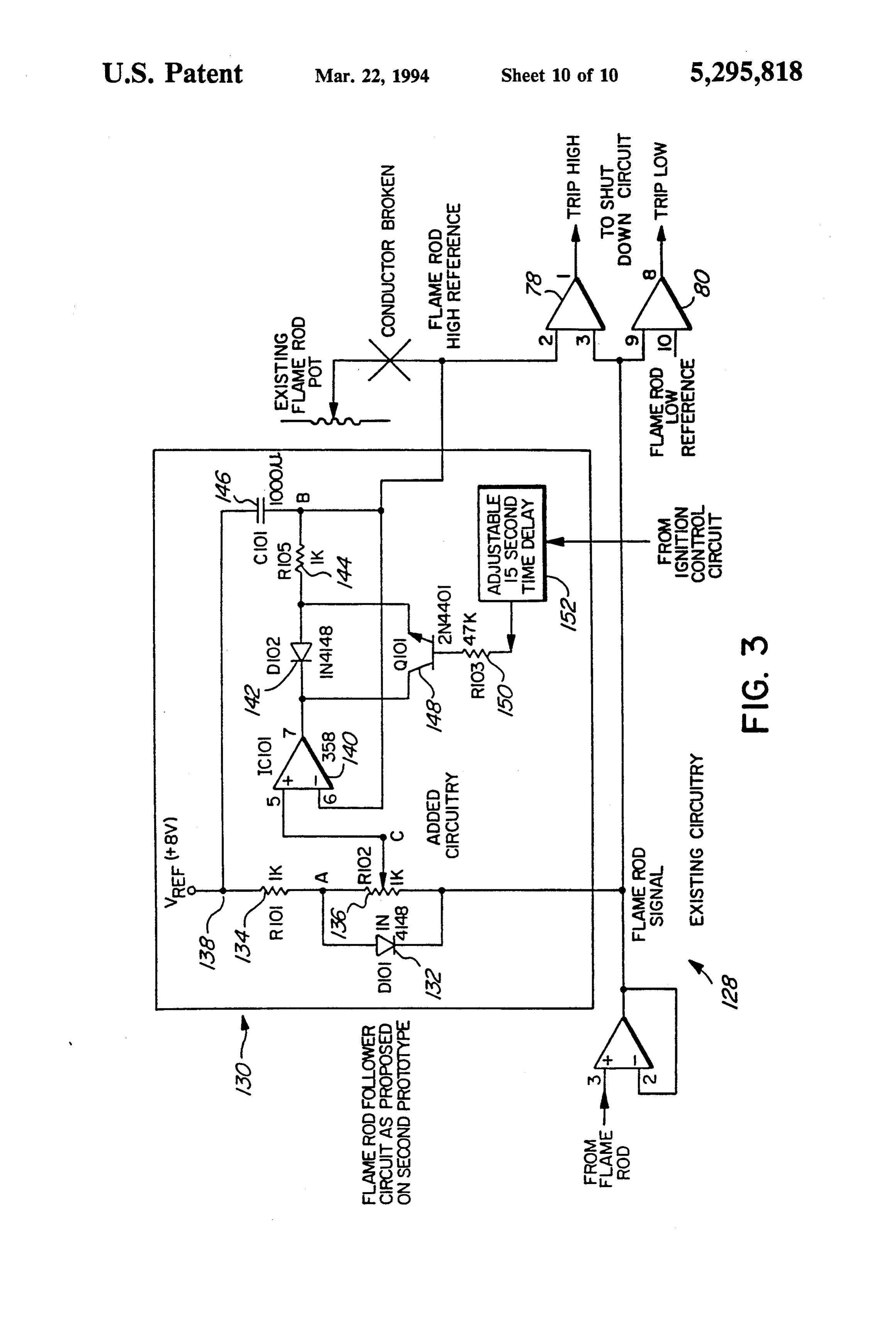
path (i.e. the flame rod 41 has short circuited). Voltage In yet a further embodiment, the flame rod 41 senses divider network 82 tests both of these conditions. When the flame by measuring the voltage being passed from there is a minimal flame current, the negative input to the flame rod 41 to the burner 10 through the flame 32. the comparator 80 (as adjusted by R19) will exceed the 20 This technique is accomplished with reference to FIG. positive input and the output will go negative, LED3 3.
will indicate a LOW FLAME condition, and a TRIP An improved flame rod sensor circuit according to signal will be initiated. When there is an overly large this embodiment is illustrated generally at 128. It com flame current, the negative input of the comparator 78 prises comparator circuits 78, 80, and dynamic high will exceed the positive input and the output will go 25 voltage reference circuit 130. The signal from flame rod negative, LED4 will indicate a FLM SHORT condi 41 is applied to comparator 80 which sets a lower limit tion, and a TRIP signal will be initiated. The compara and to comparator 78 which sets the upper limit. The tor circuit 76 provides a feedback path for the IGNI lower limit of comparator 80 is set by a fixed low volt TION SENSE signal. age reference. The upper limit of comparator 78 is set With regard to FIG. 2E, the processing of the signal 30 by a dynamic high voltage reference produced by cir from thermocouple 42 is illustrated. The faint signal is cuit 130. The dynamic high voltage reference is equal to first amplified by the differential amplifier circuit 86. the lowest value obtained by the signal from flame rod Then the amplified signal is processed by two separate 41 plus a preset offset value. Diode 132, resistor 134, and circuits. potentiometer 136 divide the potential difference be First, the comparator circuit 88 compares the ampli 35 tween a reference 138 and the signal from flame rod 41. fied signal against an absolute temperature as adjusted The potentiometer 136therefore delivers an input signal by R63. If the amplified signal represents a lower tem equal to the signal from flame rod 41 plus a preset offset perature, the comparator circuit 88 goes low, LED8 to a negative peak detector circuit comprised of an indicates a LOW TEMP condition, and a TRIP signal is op-amp 140, a diode 142, a resistor 144 and a capacitor initiated. 146. The output of the negative peak detector circuit Second, the follower circuit 90 sets a relative temper forms the dynamic high voltage reference applied to ature window that rises with the actual signal measured comparator 78. When the burner 10 is initially ignited, by thermocouple 42. If the amplified signal dips below the initial charging of capacitor 146 is facilitated by this window region, the comparator circuit 92 goes low, transistor 148, resistor 150, and timer circuit 152 which LED5 indicates an UNDER TEMP condition, and a 45 responds to a signal from the ignition control circuit of TRIP signal is initiated. If an ignition sense signal is FIG. 2A.
received by the temperature window reset circuit 94, In operation and after ignition is terminated, the volt capacitor C17 is discharged through the transistor Q4 age reading assumes its highest point, say 5 volts. As the and the window region is reset. burner 10 begins to warm up the voltage starts to drop With regard to FIG. 2F, the actual trip circuitry is SO and may eventually reach 2.5 volts. The circuit illus generally indicated at 96. When a TRIP signal is re trated in FIG. 3 will therefore allow burner 10 to follow ceived, the comparator circuit 98 changes state, driving the decreasing voltage with a window such that as long the RC network formed by variable resistor R34, resis as the voltage stays within the window, the operation of tor R40, and capacitor C21. After an RC time delay, the burner 10 will continue. Thus, as long as the voltage comparator 100 changes state, initiates an IGNITION 55 continues to drop, or remain constant, the burner 10 DISABLE signal, and forces transistor 102 into con will continue operating. If at any time the voltage duction. LED6 indicates a TRIP condition, and relay should rise, say 0.5 volts, which would put it outside or 104 switches, sending power to a fan and initiating an above the window, and stay there for the time it takes AUX signal. the safety circuit to shut down the burner 10, the burner With regard to FIG. 2G, the initiation of the AUX 10 will terminate operation. Such a rise in voltage could signal forces transistor 108 into conduction which, sub indicate a malfunction in the burner operation, such as ject to the discharge time delay of C12, lowers the unacceptable luminosity.
negative input of differential amplifier 110 with respect Many other modifications will readily occur to those to the positive input. The voltage at the output of differ skilled in the art and the specific embodiment herein ential amplifier 110 increases and which forces transis 65 described should be considered to be illustrative of the tor 112 into conduction which switches relay 114. invention only and not as limiting its scope as defined in With regard to FIG. 2H, the processing of the signal accordance with the accompanying claims. from thermocouple 44 is illustrated. The signal is first What is claimed is:
Page 16
1. In a combustion burner having a burner tube and said ignition electrode means after a predetermined time ignition electrode means for creating a primary flame period.
inside said burner tube which primary flame extends 5. The control means according to claim 2, wherein longitudinally of said burner tube during ignition of said said flame rod produces a signal voltage upon ignition combustion burner and said burner tube having a cir of said combustion burner which signal voltage de cumferentially extending flame grid thereon for accom creases as the operating temperature of said combustion modating a secondary flame on the outside of said burner increases, and further comprising comparison burner tube during self-sustaining combustion in the means to provide comparison between said signal volt burner, a control system comprising temperature sens age and upper and lower reference voltages, said signal ing means for sensing the temperature of said primary O voltage being within the range of said upper and lower flame inside said burner tube created by said ignition reference voltages, and voltage reduction means for electrode means and first control means for terminating reducing operation of said combustion burner during said ignition said signalsaid upper and lower reference voltages as voltage is reduced and wherein said second when said temperature of said primary flame is not control means terminates the operation of said combus sensed and flame monitoring means for monitoring the tion burner if said signal voltage
changes such that said presence of said secondary flame on the outside of said signal voltage is outside the range of said upper and burner tube and second control means for terminating lower reference voltages.
the operation of said combustion burner when the pres ence of said secondary flame is not sensed. 6. A control system as in claim 5 wherein said signal 2. The control system according to claim 1, wherein 20 voltage falls upon termination of said ignition. said flame monitoring means comprises a flame rod for 7. A control system as in claim 6 wherein said signal establishing an electric circuit along said flame rod and voltage falls outside said range between said upper and through said secondary flame to ground. lower reference voltages if said signal voltage rises. 3. The control system according to claim 2, wherein 8. A control system as in claim 6 wherein said signal said temperature sensing means comprises a thermo 25 voltage falls within said range between said upper and couple. lower reference voltages if said signal voltage remains 4. The control system according to claim 3, further constant or decreases. k comprising timer means for terminating the operation of x
Provenance
- Collection
- Patents citing this work
- Original assignee
- ITR Holdings Ltd
- Pages
- 16
- Method
- pdftotext (the PDF's own text layer) + pdftoppm 300dpi page scans
- Patent office record
- patents.google.com →
- Source
- Google Patents citing-documents table
- Inventors
- Edgar C. Robinson; ITR Holdings Ltd
- Published
- 1994-03-22
- Transcribed from
- patentimages.storage.googleapis.com →