patent · US2324837
Electric heater
20 July 1943
Page 1
Drawing sheet — no readable text.
Page 2
Patented July 20, 1943
UNITED STATES PATENT OFFICE
ELECTRC HEATER,
Chester I. Hall, Rexford, N. Y., assignor to Gen eral Electric Company, a corporation of New
York
Application August 29, 1942, Serial No. 456,660
This invention relates to electric heaters, more trode chamber is provided with three electrodes particularly to electric heaters of the electrode Which are adapted to be connected to the three type which function to heat a substance by pass Supply wires of a three-phase power source; the ing current through it, and it has for its object load imposed on the electrode supply system the provision of an improved electric heater of therefore is balanced.
this character. It further contemplates the provision of such This invention is particularly applicable to a chamber which will give unifolijn current, den an electric heater of the electrode type for heat Sity throughout the liquid stream, thus insuring ing liquids, such as milk, vegetable and fruit uniform heating of all particles of the liquid. juices, beer and the like in order to pasteurize the O This is accomplished by giving the electrode liquid. In order to pasteurize liquids of this Surfaces in contact with the liquid a predeter character, it is extremely important that every mined convex curvature with relation to the part of the liquid be heated to the critical pas Spacing between them.
teurizing temperature and that this tempera In addition, another object of this invention ture be held for a predetermined period of time. is the provision of an improved cooling System If this is not done, particles of the liquid may for preventing overheating of the electrode Sur retain a colony or colonies of bacteria, which faces that contact the liquid stream. En one later will grow and contaminate the Whole. form of this invention, this system includes cool In certain commercial pasteurizers now on the ing liquid passageways directed through the in market, the liquid is forced to flow upwardly : terior of the electrodes themselves. continuously through an electrode chamber, the Other objects of this invention include the walls of which are defined in part by spaced proVision of an electrode chamber structure electrodes. As the liquid passes through the Which lends itself to easy assembly and dis chamber it is heated to a predetermined tem assembly, and which is inexpensive in construc perature by the passage of , alternating current tion.
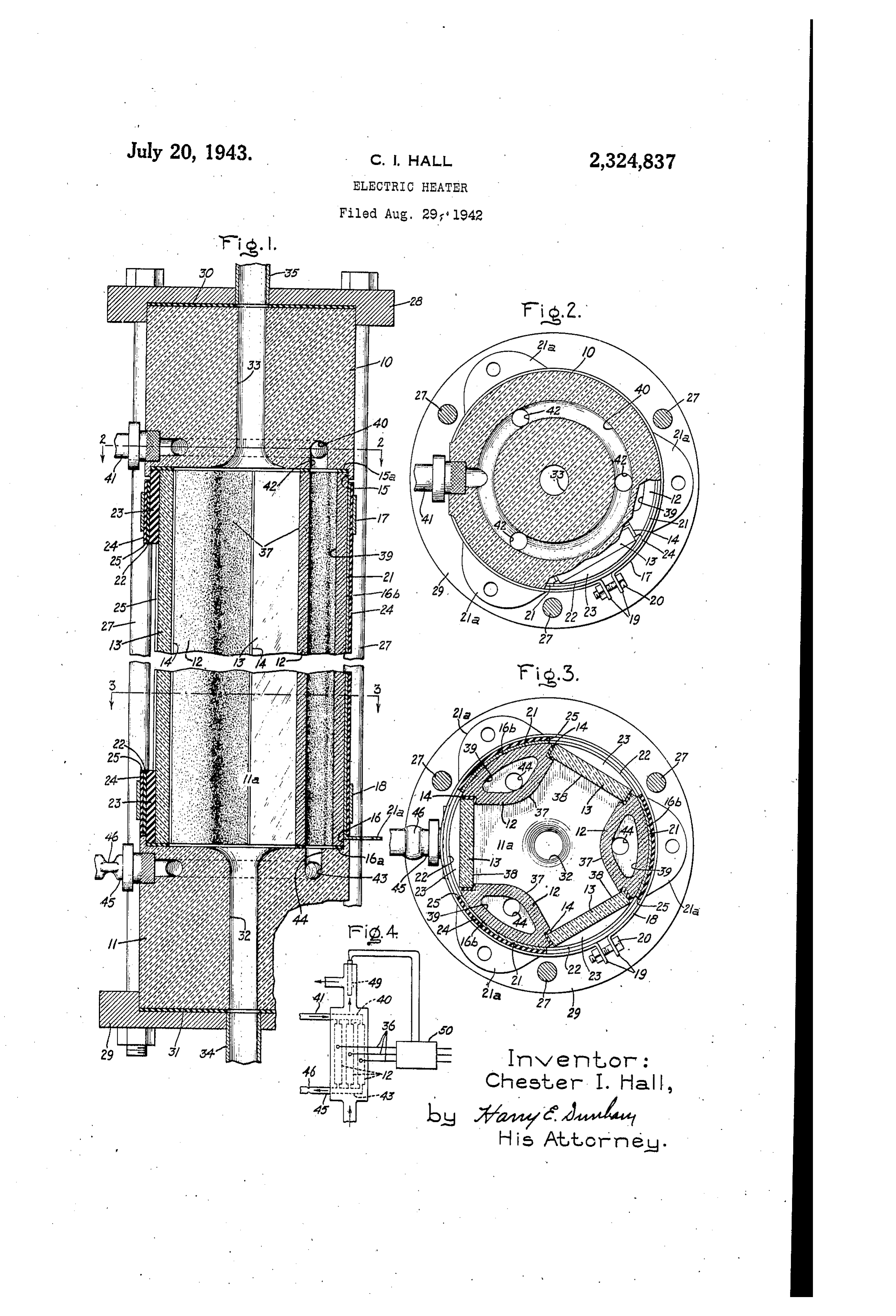
through it from one electrode to the other. Gen For a more complete understanding of this erally, these electrode chambers have had a pair invention, reference should be had to the ac of opposed electrodes which subjected the liquid companying drawing in which Fig. 1 is a verti stream of a uniform current density, and con sequently heated all particles of the liquid uni : ) cal Sectional view of a three-phase electrode pasteurizing chamber embodying this invention;
formly to insure complete pasteurization. Fig. 2 is a Sectional view taken through the line These electrode chambers inherently impose a 2-2 of Fig. 1 and looking in the direction of single phase load on the power System. This the arrows; Fig. 3 is a sectional view taken was not objectionable as long as the capacity through the line 3-3 of Fig. 1 and looking in of the apparatus was relatively Small; thus, a the direction of the arrows; and Fig. 4 is a dia milk pasteurizer, which handled about 150 gal grammatic representation of the electrode chan lons per hour, has an electrical rating of about ber of Figs. 1-3 illustrating the nanner in which 18 kilowatts, which is not great enough to in it is connected into the liquid pasteurizing cir pose too unfavorable conditions on the gener cuit, and also the way in which ii, is connected ating equipment. However, it has been proposed 40 to a three-phase electrical power source. to increase the capacity of certain milk pasteur Referring to the drawing, this invention has izing apparatus to about 1000 to 1200 gallons per been shown in One form as applied to a three hour. Such an apparatus requires an electrical phase electrode chamber for pasteuriginz milk. supply of more tihan 100 kilowatts. This chamber, as shown, comprises a pair of Such a large single phase heater when con Opposed end members-an upper ineniher 0 nected to a three-phase power System imposes and a lower member . These members are a serious unbalanced load upon the transmitting formed of any Suitable mechanically strong, elec and generating equipment, which as is well trically insulating material, such as porcelain. known is attendant with undesirable operating Mounted in the space between the end nem conditions in the equipment. bei's 9 and is an electrode chamber it. This This invention contemplates the provision of an improved pasteurizer electrode chamber iselectrodes defined by the end theinbers and i, by three 2, spaced 120° apart, and by three which will obviate this objectionable feature of electrically insulating walls 3 inserted between the single phase double electrode chamber.
In accordance with this invention, the elec 55 the electrodes. The electiodes 2, as shown, are Substantially homogeneous, and are formed of
Page 3
any suitable material-preferably carbon; and observed, therefore, that the electrodes 2 and while the Walls 3 may be made of any suitable insulating Walls 3 extend upwardly parallel to non-conducting material, I prefer to form them the direction of flow of the liquid stream. of glass. Suitable gaskets 4 are interposed be It is contemplated that the three electrode tween the electrodes 2 and the walls 3 in order contact plates 2 f will be electrically connected to make fluid-tight joints between these mem respectively with the three conductors of a three bers. It will be observed that the electrodes 2 phase Supply System 36, as shown in Fig. 4. In and glass walls 3 extend throughout the full Order that the electrodes 2 thus supplied will distance between the two end members to and , Subject the liquid stream flowing opposite them which members preferably will be provided with 0. to a uniform current density throughout, I give recesses 5 and 6 respectively in their opposed the electrode surfaces 37 which contact the surfaces to receive the end sections of the elec liquid stream a convex curvature, as shown in trodes and Walls. Inserted in these recesses be Fig. 3; the curvature of the surfaces 3 is such tween the end surfaces of the electrodes 2 and that the current density in the liquid stream in walls 3, and the bottom Walls of the recesses 5. any area normal to the direction of flow is sub are sealing gaskets 5d and 6a. Stantially uniform, whereby the liquid flowing As ShoWin, the outside surfaces 6b of the through the electrode chamber is uniformly electrodes 2 have an arcuate shape. Encircling heated. It will be observed that the surfaces 38 these surfaces so as to secure the electrodes. 2 of the Walls 3 contacting the liquid stream will and walls f3 together are upper and lower clamp 20 be given a plane surface normal to the milk flow. ing rings and 8. Each of these members is The electrodes 2 must be cooled in order to in the form of a broken ring provided with out prevent them from attaining too high a tem Wardly extending flanges. 9 at the ends. These perature which might result in burning particles flanges are clamped together by means of of the liquid. The cooling system arranged in bolts 20. 25 accordance with this invention includes passage The clamping rings 7 and 8 also function to ways 39 which are formed in the electrodes them clamp suitable electrical supply contact mem Selves. In other words, the electrodes are hol bers 2 f to the Outer Surfaces 6b of the elec loW and are So arranged that a relatively large trodes. These members have about the same liquid passageway is formed through them. Cool. length as the electrodes and extend from one : ing Water is forced through the electrodes in a direction opposite to the direction of flow of the . . edge thereof to the other, and have flanges 2 a.
formed on their lower ends with which to make fluid in the electrode chamber fia. The cooling Water is forced continuously into the upper ends electrical connections with a Source of electrical
Supply. Interposed between the end edges of of the electrodes, is caused to flow down through the contacts 2 are arcuate-shaped insulating 35 them, and then is discharged from the electrodes at the bottom. En order to supply the electrodes sheets 22, which will be made of any suitable with the cooling water the upper end member 0 material, such as Textolite. Preferably and as is provided With a circular passageway 40 into shown, suitable shims 23 will be inserted between which the water is fed by means of a supply pipe the tops and bottoms of the glass insulating 40 walls 3, and the insulating sheets. 22. These 4. The circular passageway 40 is connected with the three electrode chambers 39 by three also will be made of an electrically insulating Vertical material, such as Textolite. passageways 42. The lower end member Surrounding the contacts 2i and the insulat is provided with a similar circular passageway 43 connected with the lower ends of the channels ing sheets 22 is a cylinder 25 formed of a suit 45 39 able electrically insulating material, such as by means of three passageways 44. Connected Textolite. This cylinder also is secured by the With the discharge passageway 43 is a discharge rings and i8, as shown. . - pipe 45 which has a pinched section 46 that func . The outer insulating cylinder 24 is provided tions to keep full columns of the cooling water with three windows 25 opposite the glass in in As thepointed hollow out electrodes.
previously, the three electrodes sulating walls 3 so that the milk stream may be are connected to the three conductors respective viewed.
The two end sections 9 and
are clamped ly of a three-phase alternating current supply together by means of a plurality of elongated Source 36. The Voltage of this source is con bolts 27, which, as shown, are directed through 55 trolled by means of a temperature-responsive upper and lower metallic end plates. 28 and 29 the milk49stream element which responds to the temperature of flowing away from the electrode fitted to the top and bottom surfaces of the chamber So that a substantially constant tem end member's 9. and so as to clamp them to perature is held in the milk stream. While any gether. Interposed between these surfaces of Suitable temperature responsive element may be the end members and the plates 28 and 29 are used, I prefer to use an element of the type de suitable sealing gaskets 3 and 3 respectively. 60 scribed and claimed in my Patent No. 2.271,975, The end member has a fluid supply pas dated February 3, 1942. As there described, this sageway 32 connected with the electrode cham element is such that its electrical resistance varies ber a while the end member 8 is provided Widely. With with a fluid discharge passageway 33 connected 65 controller 50temperature changes. Any suitable which will operate responsively to
With this chamber. It will be understood that in the operation of the apparatus, the milk Such the changes in resistance may be used to control
Voltage applied to the electrodes in order to stream to be treated is forced upwardly through hold the temperature constant. the passageway 32 into the electrode chamber It Will be observed that one of the features of ila and thence is discharged out through the 70 this invention is the provision of means for read passageway 33 to conduct the milk away from ily disassembling the electrode chamber and for - the apparatus; as shown, a suitable milk Supply eassembling it. To disassemble the chamber, it pipe 34 communicates with the passageway. 32, is merely necessary to remove the large bolts 2 while a suitable discharge pipe 35 is connected Which releases the end members: 10 and from with the discharge passageway 33. It Will be 75 the electrodes 2 and their insulating walls 3.
Page 4
These walls may be separated merely by removing 4. An electric heater comprising a pair of Op the bolts 25 of the clamping rings. To reassem ble, it is of course only necessary to place the posed end neinbers formed of electrically insu walls 2 and 3 together, along with the supply lating material, said members having shallow contacts 2, insulating members 22, and insulat circular recesses in their faces opposing each ing cylinder 24, and then clamp these members other, an electrode assembly having a plurality together by the two rings 7 and 8. of spaced electrodes having arcuate-shaped ex While I have shown a particular embodiment terior surfaces, a plurality of insulating mem of my invention, it will be understood, of course, bers between said electrodes, readily detachable bands clamping said electrodes and insulating that I do not Wish to be limited thereto Since 10. members many modifications may be made, and I, there together, said asserably being interposed fore, contemplate by the appended claims to cover between said end nembers so that its ends are any Such linodifications as fall Within the true received in Said recesses, and readily detachable Spirit and Scope of my invention. clamping gether.
means Securing Said end members to
What I claim as new and desire to secure by 15 5. A device for heating liquid by passing an Letters Patent in the United States is:
1. An electric pasteurizing device comprising a electric current therethrough comprising a pair pair of electrically insulating end members, a of end members formed of electrically insulat plurality of Spaced hollow electrodes extending ing material, a pirality of spaced electrodes ex between Said end members, Said end members tending between said end members, insulating members exteinding between said el33trodes, Said having fluid paSSageWays therein arranged to in 20 end terconnect said electrodes so that a cooling fluid members, electrodas, and in Slating nei may be circulated between Said end members bers being arranged to define an eiectrodie cham through the interior of Said electrodes, insulat ber for heating liquid contained therein, Said electrodes having cooling passageways extending ing members extending between said electrodes, 25 through the and said end members having and Said end members, electrodes and insulating fiuid passageways therein arranged to interCon members being arranged to define a heating nect said electrodes So that a cooling fuid may chamber through.
for heating liquid circulated there be circulated between said end members thi'ough the interior of said electrodes.
2. Electric pasteurizing apparatus adapted to 30 6. Electric pasteurizing apparatus adapted to be energized froin a polyphase Source of electric be ensergized from a Scurce of three-phase elec power comprising an electric heater having a tric power comprising an electic ineater having plurality of Spaced electicodes adapted to be con a chamber through which liquid to be heated is nected to the various phases of Said Source of circulated, said chanber having three equally power, and also having a plurality of spaced spaced electrodes and three equally Spaced elec electrically insulating members interposed be trically insulating members between Said elec tween said electrodes, said electrodes and insu trodes, said electrodes and insulating members lating members defining a chamber in Which the defining the chamber through which the liquid liquid to be heated is received, all of the Surface to be heated is circulated, and said electrodes areas of Said electrodes that contact With the () and insulating members extending Substantially liquid have a predetermined form such that the parallel to the direction of the liquid flow, the current density through the liquid is Substan Surfaces of said insulating members in contact tially uniform whereby the liquid is substantially with the liquid being Substantially flat, and the uniformly heated. surfaces of said electrodes in Contact With said 3. Pasteurizing apparatus Cornprising an elec liquid having a convex curvature such that the tric heater having an electrode chamber through current density through the liquid in any area which liquid to be heated is circulated in a pre normal to the direction of flow is substantially determined direction, a plurality of spaced elec uniform. Whereby liquid flowing through said trodes disposed in said chamber and extending chamber is substantially uniformly heated. in the direction of flow of liquid through said : 7. A milk pasteurizing electrode having sub chamber, Said electrodes being hollow So as to stantially homogeneous Walls formed of carbon, define internal passageways extending there one of said Walls having a surface adapted to through, and means for circulating a cooling fluid be exposed to the milk stream, and said walls through said electrodes So that it flows in the defining an internal passageway through the elec direction opposite of the direction of flow of said 55 trode for receiving a cooling fluid. liquid.
CHESTER I. HALL.
Provenance
- Collection
- Cited prior art
- Original PDF
- patentimages.storage.googleapis.com →
- Filed
- 1942-08-29
- Pages
- 4
- Method
- pdftotext (the PDF's own text layer) + pdftoppm 300dpi page scans
- Source
- Google Patents bibliographic record
- Granted
- 1943-07-20
- Inventors
- Chester I Hall; General Electric Co
- Transcribed from
- patentimages.storage.googleapis.com →