patent · US3469026
Tv pickup and projection system with camera having fiber optic hemispherical lens
23 September 1969
Page 1 — bibliographic record
Sept. 23, 1969 L. WINK ET AL 3,469,026
TW PICKUP AND PROJECTION SYSTEM WITH CAMERA HAVING
FIBER OPTIC HEMISPHERICAL LENS
Filed April 22, 1966 3 Sheets-Sheet
No OR CLAssIF.
ZaaZZZZZ
INVENTOR
Page 2
Sept. 23, 1969 L. WINK ETAL 3,469,026.
TW PICKUP AND PROJECTION SYSTEM WITH CAMERA HAVING
FIBER OPTIC HEMISPHERICAL LENS
Filed April 22, 1966 3 Sheets-Sheet :
NYNNNNNNNNNNN
SNSS
VARABLE VARIABLE
OSCILLATOR AMPLIFER
A VENTORs
Page 3
Drawing sheet — no readable text.
Page 4
United States Patent Office 3,469,026 Patented Sept. 23, 1969
3,469,026 A further object of this invention is to provide optical TW PICKUP AND PROJECTION SYSTEM WITH pickup means which will be in focus independently of the CAMERA, HAVING FIBER OPTC HEMI. distance of the object from the objective lens. SPHERICAL LENS '.. The capability of the TV pickup and transmittal system Leon Winik, New York, and George Doundoulakis, North of the invention would also be very desirable in a sub Bellmore, N.Y., assignors, by direct and mesne assigne marine periscope, for instance, where the naval officers ments, of fifteen percent to Albert C. Nolte, Jr., Oyster can have simultaneous view of the entire surroundings Bay Cove, N.Y. while sitting comfortably under a dome rotunda projec Filed Apr. 22, 1966, Ser. No. 544,590 tion screen. A similar case exists in viewing the air traffic
U.S. C. 178-6.8 11. Claims 10 from an airport observation tower. - With the foregoing and other objects in view, the in vention provides a novel means of high resolution light
ABSTRACT OF THE DISCLOSURE pickup from a desired direction and efficient means for guiding the highly resolved light onto a corresponding
A fiber optical device wherein the ratio of the core to cladding indices of refraction varies along the optical point onfor ascanning widicon sensitive surface, with appropriate fiber length and means for providing a television camera means means for scanning the vidicon surface and appropriate special projecting means in synchro system whereby the fiber optic device is utilized as an nism with the widicon scanning means for the TV repro objective lens. duction of a large angle image. The invention further provides a novel arrangement and combination of ele
This invention relates to TV pickup and projection sys ments and in the details of construction, herein after de tems and more particularly to a TV system using fiber scribed and claimed, it is to be understood that changes in optics for TV pickup of images to be projected on a dome the precise embodiments of the invention, as herein dis
The present TV systems are restricted to a relatively 25 closed, may be made within the scope of the invention as small objective angle and the projection of the image claimed in the appended claims without departing from the spirit of the invention.
occurs on a rather flat or slightly curved surface. In addi Other objects and features of the invention will appear tion the present TV pickup systems provide only a limited as the description of the particular embodiments selected depth of focus.
The present invention provides means for a full hemi 30 to Inillustrate the the invention are described.
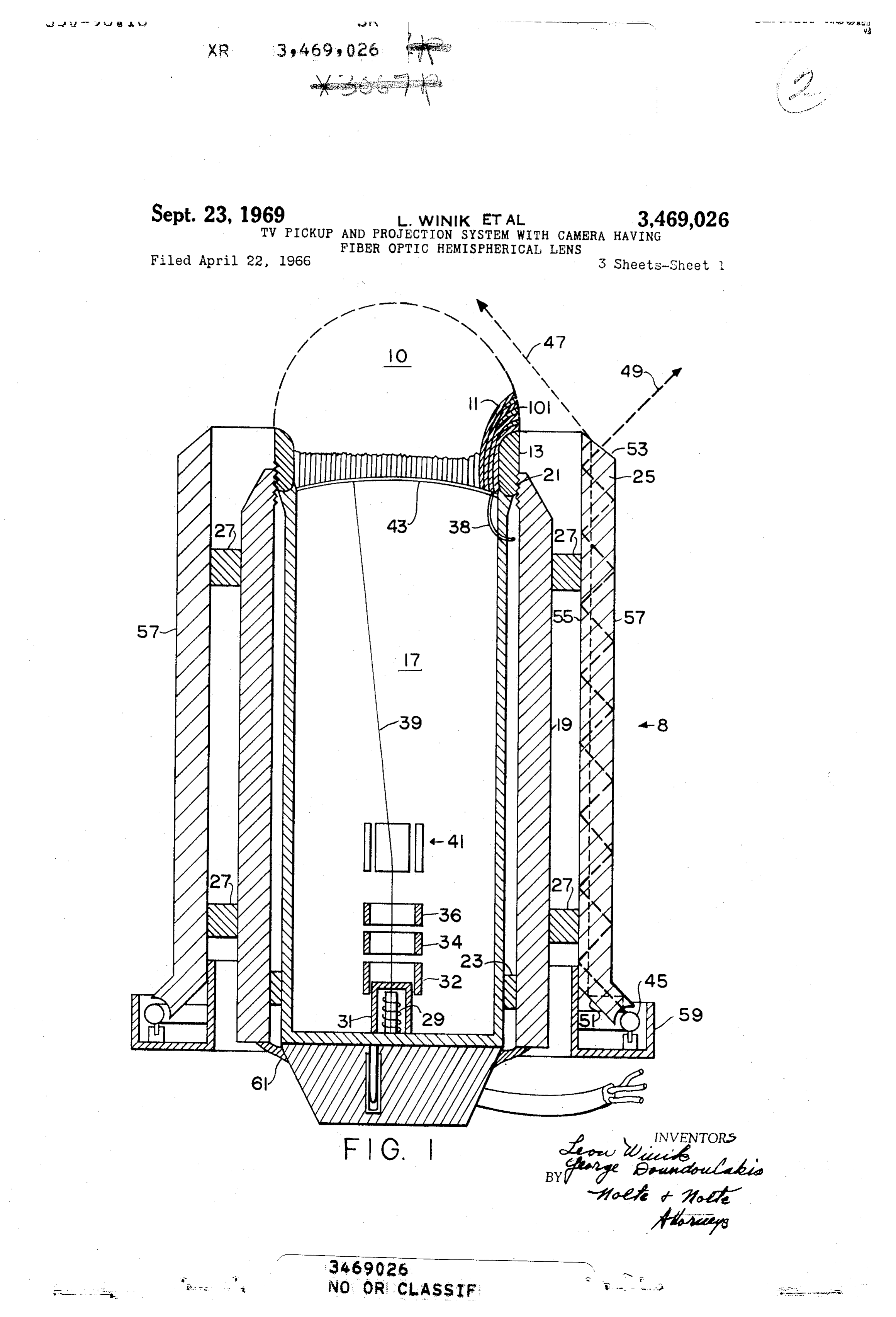
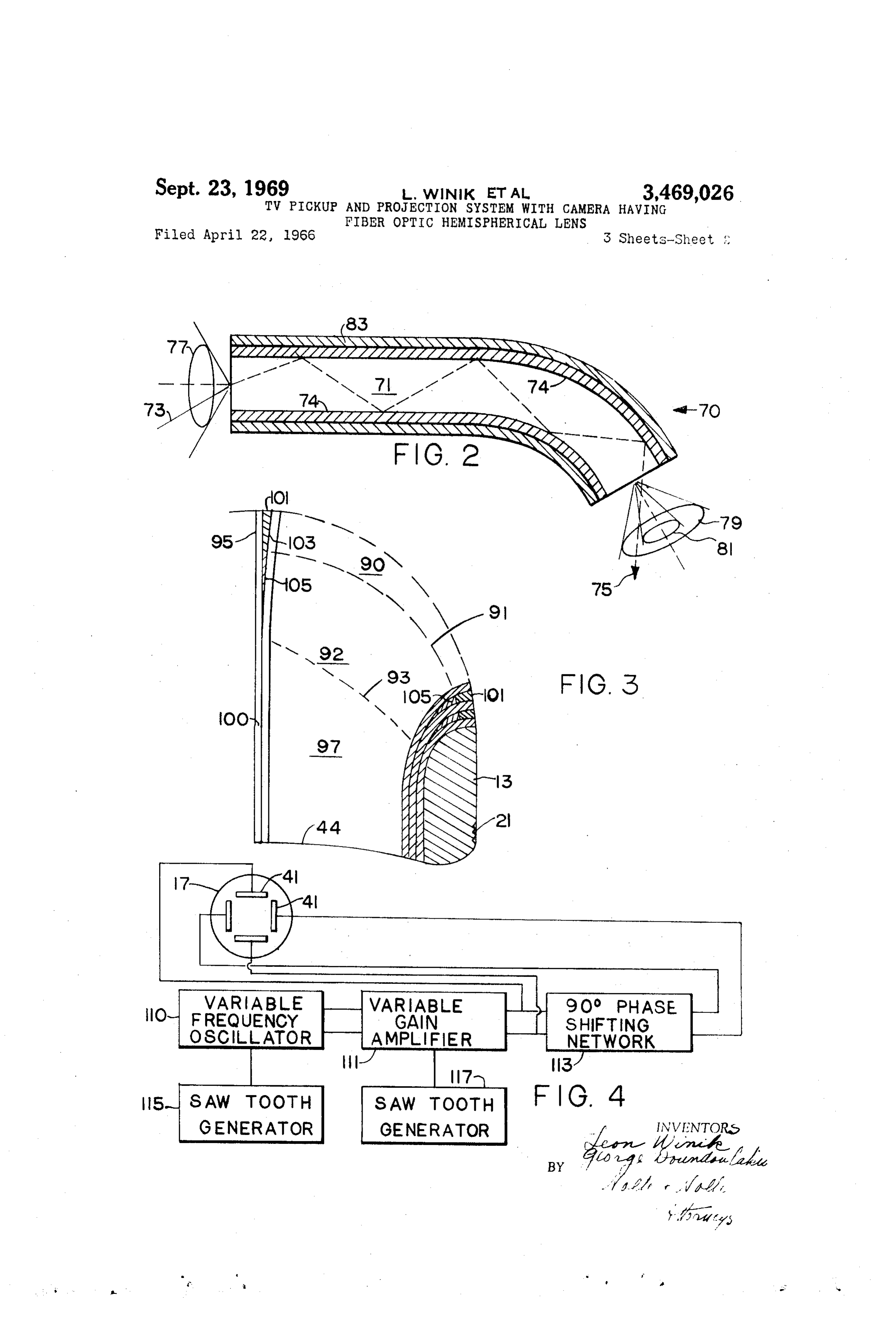
accompanying drawings, which form part of this spherical pickup, in focus, regardless of the objects' dis specification, wherein like characters of reference have tance and means for projection of such images on a dome been applied to corresponding parts: rotunda-like screen. FIG. 1 is a magnified cross sectional elevation view of a A viewer, positioned under such a dome rotunda pro TV pickup head in accordance with this invention; jection screen can envisage a realistic image covering his FIG. 2 is a cross sectional schematic diagram of an entire horizon. optic fiber illustrating main features and the principles An important application of the invention is the pro employed in the transmission of light through curved jection of actual happenings within a surgical incision paths in the fiber;
during an operation. Heretofore, even the surgeon had but FIG. 3 is a cross sectional detailed elevation view of a limited view of the interior of a surgical incision. With 40 the optical fiber objective lens which is a part of the the help of the present invention, doctors can be quickly pick up head shown in FIG. 1;
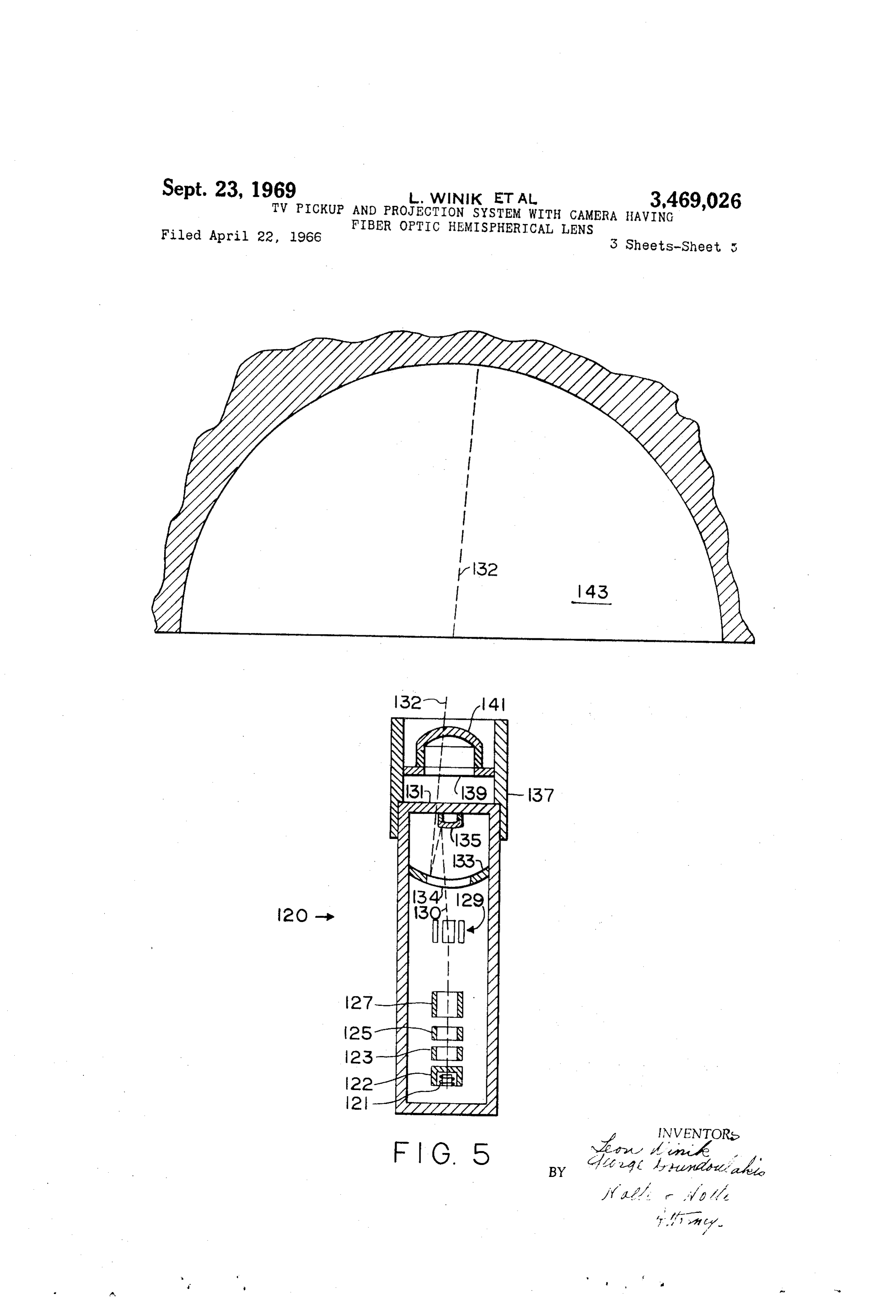
trained by observing the progress of surgical operations FIG. 4 is a schematic block diagram showing the elec closely. In addition trained physicians can also remotely tronic circuitry used to supply appropriate scanning sig follow the operation and can warn the operating surgeon nals for the image pick up and image projection means; of a situation of which the surgeon himself could possibly 45 and be unaware, because of his limited view. For instance, FIG. 5 is a cross sectional elevation view of the pro the formation of air bubbles in the blood vascular system jection system in relation to a dome-like screen. during vascular surgery can, with the present invention, Conventional refractive optics cannot provide a hemi be detected. spherical coverage. Spherical aberration and other optical It is, therefore, a principal object of the present inven 50 defects are introduced as the angle of view of the image tion to provide a TV camera system capable of hemi is widened. It can be easily proved that there is no re spherical coverage and projection onto a hemispherical fractive lens shape, which can focus an entire hemisphere SCeen onto a single image. The present invention overcomes the Another object of the present invention is to develop a limitations of conventional refractive optics by the use of TV pickup means capable of discretely receiving light optical fibers, whose light receiving ends lie on a hemi from a multiplicity of directions, the totality of such spherical surface. The optical fibers conduct the received multiplicity of directions defining a full hemisphere, light through a curved path and terminate on the sensitive whereby by guiding the light from each direction onto surface of a widicon tube.
corresponding points of a conventional vidicon pickup Referring now particularly to FIG. 1, there is shown a tube, an image of an entire hemisphere is formed and 60 pick up head 8 comprising an objective lens 10, made up subsequently projected onto a dome-like screen. of a plurality of optical fibers and supported by a ring Another object of the present invention is to provide 13. The ring 13 is attached to a glass envelope of a miniature TV pickup means capable of hemispherical cov vidicon pick up tube 17. The assembly of the objective erage. lens 10 and vidicon pickup tube 17 are supported onto a It is yet another object of the present invention to pro 65 tube 19 by means of a threading 21, and space ring 23. vide high resolution light pickup means, and low loss A cylinder 25, made of a transparent, light refractive light guiding means for accurately focusing a hemispheri material is also supported coaxially around the tube 1.9 cal image onto a widicon light sensitive surface. through space rings 27. The vidicon tube comprises a It is still another object of the present invention to provide proper widicon and projection tube scanning 70 3. Thefilament heater heated 29 housed within a cylindrical cathode cathode 31 along with electronic focus means which may effectively project a hemispherical ing elements 33, 35 and 37, commonly referred to as an image onto a dome rotunda screen. electron gun assembly, serves to generate and project
Page 5
forward a beam of electrons 39. Two pairs of electro The present invention accomplishes simultaneously a static deflection plates 41, serve to deflect the electron small numerical aperture, corresponding to a high optical beam 39 in two coordinates, to a degree proportional to resolution, together with a small critical angle, 6 cor an electric potential applied between plates 41. A light responding to low transmission loss, higher isolation be sensitive surface 43 loses electrons and is charged posi tween fibers (lower cross talk between fibers) and greater tively by the light conducted through the optic fibers 11. bending capability by employing different index of clad The electron beam 39 scans the surface 43 and replaces ding material at different segments along the optic fibers. the electronic charge lost between successive scans. An It is also customary to apply a second coating 83 around equivalent electronic charge in the form of current is de the fibers referred to as E.M.C. (extra mural cladding) tected to represent the amount of illumination received O or E.M.A. (extra mural absorption). The E.M.A. coat by the portion of the sensitive surface being scanned. The ing serves to absorb large angle rays and therefore in light received by the optical fibers may be generated by creases resolution and lowers cross talk between fibers. the object itself or may be supplied by any source of light. FIG. 3, which shows a portion of the optic fiber ob Pickup head 8 also provides self illumination supplied jective lens in greater detail, illustrates the difference in by a lamp 45. The transparent cylinder 25 serves to con 15 the coating of optic fiber core from the surface of the ob duct light from a lamp 45 to illuminate the object viewed jective lens 10, along the length of the fiber, to the end by the lens 10. The two extreme rays 47 and 49, shown in FIG. 1, serve to illustrate the relatively wide angle of of The the fiber at the light sensitive surface 43 of vidicon 17. objective lens 10 is divided into three regions. The illumination which can be achieved by this configuration. first region 90 extending from the surface of the lens 10 Ray 47 is shown to suffer a single reflection on a surface 20 to plane 91 may be called the "directive region' since 51 and a single refraction by a surface 53 which directs it serves to increase the directivity of the light absorption. i: in front of the lens 10; while the ray 49 is shown to The second region extends between the planes 91 and undergo a plurality of reflections on surfaces 55 and 57 93 and may be called the "curved region' since it serves and finally to emerge in a direction away from the ob jective lens 10. The transparent cylinder 25 may be made 25 ato single bend the rays from the various angles of incidence into direction, parallel to the center optic fiber 95.
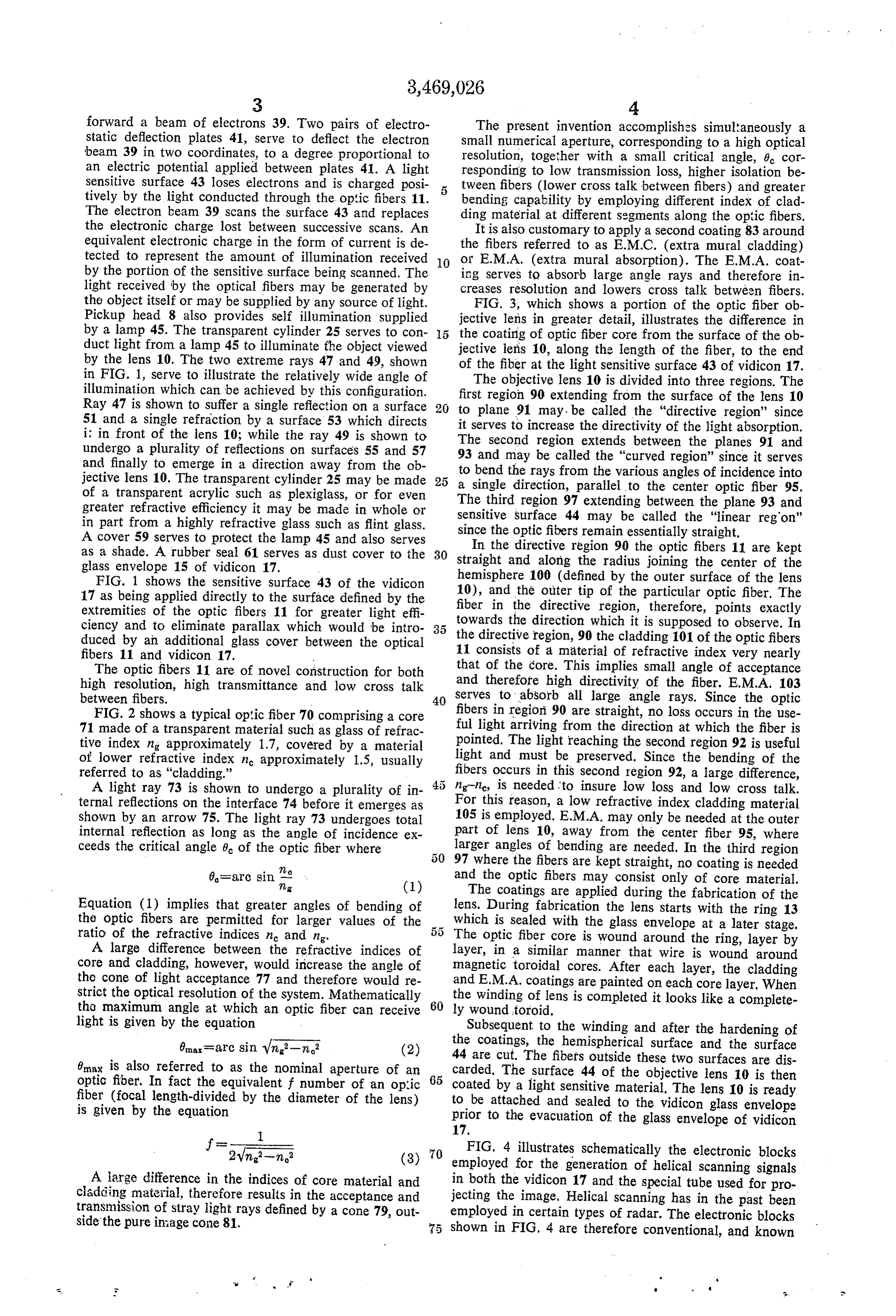
of a transparent acrylic such as plexiglass, or for even The third region 97 extending between the plane 93 and greater refractive efficiency it may be made in whole or sensitive surface 44 may be called the "linear regon' in part from a highly refractive glass such as flint glass. since the optic fibers remain essentially straight. A cover 59 serves to protect the lamp 45 and also serves In the directive region 90 the optic fibers 11 are kept as a shade. A rubber seal 61 serves as dust cover to the 30 glass envelope 15 of vidicon 17. straight and along the radius joining the center of the FIG. 1 shows the sensitive surface 43 of the widicon hemisphere 100 (defined by the outer surface of the lens 17 as being applied directly to the surface defined by the 10), and the outer tip of the particular optic fiber. The extremities of the optic fibers 11 for greater light effi fiber in the directive region, therefore, points exactly ciency and to eliminate parallax which would be intro 35 towards the direction which it is supposed to observe. In duced by an additional glass cover between the optical the directive region, 90 the cladding 101 of the optic fibers fibers 11 and vidicon 17. Y 11 consists of a material of refractive index very nearly The optic fibers 11 are of novel construction for both that of the core. This implies small angle of acceptance high resolution, high transmittance and low cross talk and therefore high directivity of the fiber. E.M.A. 103 between fibers, 40 serves to absorb all large angle rays. Since the optic FIG. 2 shows a typical optic fiber 70 comprising a core fibers in region 90 are straight, no loss occurs in the use 71 made of a transparent material such as glass of refrac ful light arriving from the direction at which the fiber is tive index n approximately 1.7, covered by a material pointed. The light reaching the second region 92 is useful of lower refractive index n approximately 1.5, usually light and must be preserved. Since the bending of the referred to as "cladding.' fibers occurs in this second region 92, a large difference, A light ray 73 is shown to undergo a plurality of in ng-nic, is needed to insure low loss and low cross talk. ternal reflections on the interface 74 before it emerges as For this reason, a low refractive index cladding material shown by an arrow 75. The light ray 73 undergoes total 105 is employed. E.M.A. may only be needed at the outer internal reflection as long as the angle of incidence ex part of lens 10, away from the center fiber 95, where ceeds the critical angle 8 of the optic fiber where larger angles of bending are needed. In the third region 97 where the fibers are kept straight, no coating is needed 0=arc sin 7,g and the optic fibers may consist only of core material. (1) The coatings are applied during the fabrication of the
Equation (1) implies that greater angles of bending of lens. During fabrication the lens starts with the ring 13 the optic fibers are permitted for larger values of the which is sealed with the glass envelope at a later stage. ratio of the refractive indices me and n. The optic fiber core is wound around the ring, layer by A large difference between the refractive indices of layer, in a similar manner that wire is wound around core and cladding, however, would increase the angle of magnetic toroidal cores. After each layer, the cladding the cone of light acceptance 77 and therefore would re and E.M.A. coatings are painted on each core layer. When strict the optical resolution of the system. Mathematically the winding of lens is completed it looks like a complete tho maximum angle at which an optic fiber can receive 60 ly wound toroid.
light is given by the equation Subsequent to the winding and after the hardening of 0n-arc sin Vn-n (2) the coatings, the hemispherical surface and the surface 44 are cut. The fibers outside these two surfaces are dis 6max is also referred to as the nominal aperture of an carded. The surface 44 of the objective lens 10 is then optic fiber. In fact the equivalent f number of an optic 65 coated by a light sensitive material. The lens 10 is ready fiber (focal length-divided by the diameter of the lens) to be attached and sealed to the vidicon glass envelope is given by the equation prior to the evacuation of the glass envelope of widicon
70 FIG. 4 illustrates schematically the electronic blocks employed for the generation of helical scanning signals
A large difference in the indices of core material and in both the vidicon 17 and the special tube used for pro cladding material, therefore results in the acceptance and jecting the image. Helical scanning has in the past been transmission of stray light rays defined by a cone 79, out employed in certain types of radar. The electronic blocks side the pure inage come 81. 75 shown in FIG, 4 are therefore conventional, and known
Page 6
to those versed in the art. Only minor modifications are What we claim is:
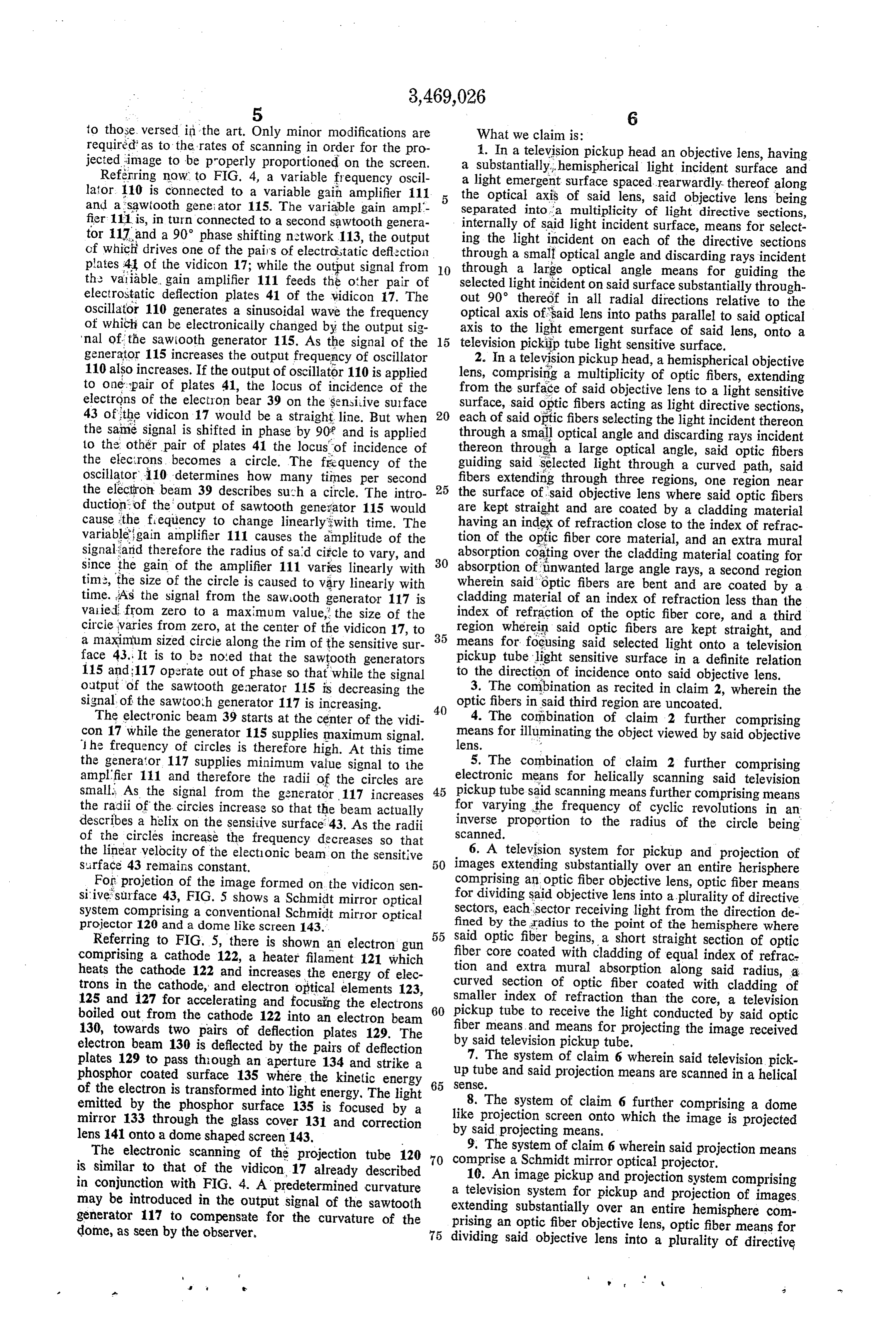
required as to the rates of scanning in order for the pro 1. In a television pickup head an objective lens, having jected image to be properly proportioned on the screen. a substantially, hemispherical light incident surface and Referring now to FIG. 4, a variable frequency oscil a light emergent surface spaced rearwardly thereof along lator. 110 is connected to a variable gain amplifier 111 the optical axis of said lens, said objective lens being and a sawtooth geneiator 115. The variable gain ampl fier 111 is, in turn connected to a second sawtooth genera separated into a multiplicity of light directive sections, tor 117 and a 90° phase shifting network 113, the output ing the light said internally of light incident surface, means for select of which drives one of the pairs of electrostatic deflèction through a small optical on incident each of the directive sections angle and discarding rays incident plates 4 of the vidicon 17; while the output signal from O through a large optical angle means for guiding the the variable, gain amplifier 111 feeds the other pair of selected light incident on said surface substantially through electrostatic deflection plates 41 of the vidicon 17. The out 90° theredf in all radial directions relative to the oscillator 110 generates a sinusoidal wave the frequency optical axis of said lens into paths parallel to said optical of which can be electronically changed by the output sig axis to the light emergent surface of said lens, onto a 'nal of the sawtooth generator 115. As the signal of the 15 television pickip tube light sensitive surface. generator 115 increases the output frequency of oscillator 110 also increases. If the output of oscillator 110 is applied lens,2. comprising
In a television pickup head, a hemispherical objective a multiplicity of optic fibers, extending to one pair of plates 41, the locus of incidence of the electrons of the electron bear 39 on the sensitive surface surface, said opticoffibers from the surface said objective lens to a light sensitive acting as light directive sections, 43 of the vidicon 17 would be a straight line. But when 20 each of said optic fibers selecting the light incident thereon the same signal is shifted in phase by 90 and is applied through a small optical angle and discarding rays incident to the other pair of plates 41 the locus of incidence of thereon through a large optical angle, said optic fibers the electrons becomes a circle. The frequency of the guiding said selected light through a curved path, said oscillator 110 determines how many times per second 25 fibers extending through three regions, one region near the electron beam 39 describes such a circle. The intro the surface of said objective lens where said optic fibers ion; of the output of sawtooth generator 115 would are kept straight and are coated by a cladding material cause the frequency to change linearly with time. The having an index of refraction close to the index of refrac variable gain amplifier 111 causes the amplitude of the tion of the optic fiber core material, and an extra mural signal and therefore the radius of said circle to vary, and absorption coating over the cladding material coating for since the gain of the amplifier 111 varies linearly with 30 absorption of inwanted large angle rays, a second region time, the size of the circle is caused to vary linearly with wherein said optic fibers are bent and are coated by a time. As the signal from the saw looth generator 117 is cladding material of an index of refraction less than the varied from zero to a maximum value, the size of the index of refraction of the optic fiber core, and a third circie varies from zero, at the center of the vidicon 17, to 35 region wherein said optic fibers are kept straight, and a maximum sized circle along the rim of the sensitive sur means for focusing said selected light onto a television face 43. It is to be noted that the sawtooth generators pickup tube light sensitive surface in a definite relation 115 and 117 operate out of phase so that while the signal to the direction of incidence onto said objective lens. output of the sawtooth generator 115 is decreasing the 3. The combination as recited in claim 2, wherein the signal of the sawtooth generator 117 is increasing. 40 optic fibers in said third region are uncoated. The electronic beam 39 starts at the center of the vidi 4. The combination of claim 2 further comprising con 17 while the generator 115 supplies maximum signal. lens. means for illuminating the object viewed by said objective he frequency of circles is therefore high. At this time ".
the generator 117 supplies minimum value signal to the 5. The combination of claim 2 further comprising amplifier 111 and therefore the radii of the circles are electronic means for helically scanning said television small. As the signal from the generator. 117 increases 45 pickup tube said scanning means further comprising means the radii of the circles increase so that the beam actually for varying the frequency of cyclic revolutions in an describes a helix on the sensitive surface 43. As the radii inverse proportion to the radius of the circle being of the circles increase the frequency decreases so that scanned. 6. A television system for pickup and projection of the linear velocity of the electionic beam on the sensitive surface 43 remains constant. 50 images extending substantially over an entire herisphere For projetion of the image formed on the vidicon sen comprising an optic fiber objective lens, optic fiber means sitive surface 43, FIG. 5 shows a Schmidt mirror optical for dividing said objective lens into a plurality of directive system comprising a conventional Schmidt mirror optical sectors, each sector receiving light from the direction de projector 120 and a dome like screen 143. fined by the radius to the point of the hemisphere where Referring to FIG. 5, there is shown an electron gun 55 fiber said optic fiber begins, a short straight section of optic comprising a cathode 122, a heater filament 121 which core coated with cladding of equal index of refrace heats the cathode 122 and increases the energy of elec curved tion and extra mural absorption along said radius, a trons in the cathode, and electron optical elements 123, smaller section of optic fiber coated with cladding of index of refraction than the core, a television 125 and 127 for accelerating and focusing the electrons 60 boiled out from the cathode 122 into an electron beam pickup tube to receive the light conducted by said optic 130, towards two pairs of deflection plates 129. The fiber means, and means for projecting the image received electron beam 130 is deflected by the pairs of deflection by said television pickup tube.
plates 129 to pass though an aperture 134 and strike a 7. The system of claim 6 wherein said television pick phosphor coated surface 135 where the kinetic energy 65 up tube and said projection means are scanned in a helical of the electron is transformed into light energy, The light SeSc. 8. The system of claim 6 further comprising a dome emitted by the phosphor surface 135 is focused by a mirror 133 through the glass cover 131 and correction like projection screen onto which the image is projected by said projecting means.
lens 141 onto a dome shaped screen 143. 9. The system of claim 6 wherein said projection means The electronic scanning of the projection tube 120 is similar to that of the vidicon, 17 already described 70 comprise a Schmidt mirror optical projector. in conjunction with FIG, 4. A predetermined curvature a televisionimage 10. An pickup and projection system comprising system for pickup and projection of images may be introduced in the output signal of the sawtooth extending substantially over an entire hemisphere com generator 117 to compensate for the curvature of the prising an optic fiber objective lens, optic fiber means for dome, as seen by the observer, 75 dividing said objective lens into a plurality of directive
Page 7
sectors, each sector receiving light from the direction de 2,995,970 8/1961 Hicks et al. ----------- 65-4 fined by the radius to the point of the hemisphere where 3,033,071 5/1962 Hicks -------------- 65-4 X said optic fiber begins, a short straight section of optic 3,132,646 5/1964 Hett ----------------- 128-6 fiber core coated with cladding of equal index of refrac 3,175,037 3/1965 Padgitt ------------ 17.8-7.85 tion and extra mural absorption along said radius, a 3,275,743 9/1966 Conant ----------- 1786.8 X curved section of optic fiber coated with cladding of 5 smaller index of refraction than the core, a television OTHER REFERENCES pickup tube to receive the light conducted by said optic Book: Encyclopedia on Cathode-Ray Oscilloscopes and fiber means, a substantially hemispherical screen remotely located from said pickup means and means for transmitting l0 Their Uses, pp. 7-74 to 7-76, by: John F. Rider and Seymore D. Uslan published by: John F. Rider publisher, the image received by said objective lens to said remote
SCeel. Inc., received in Patent Office Mar. 2, 1964. 11. The system of claim 10 wherein said pickup means is a pencil shaped miniature television camera. ROBERT L. GRIFFIN, Primary Examiner References Cited 15 R. K. ECKERT, Jr., Assistant Examiner
UNITED STATES PATENTS U.S. C. X.R.

Provenance
- Collection
- Cited prior art
- Original PDF
- patentimages.storage.googleapis.com →
- Filed
- 1966-04-22
- Pages
- 7
- Method
- pdftotext (the PDF's own text layer) + pdftoppm 300dpi page scans
- Source
- Google Patents bibliographic record
- Granted
- 1969-09-23
- Inventors
- Leon Winik; George Doundoulakis
- Transcribed from
- patentimages.storage.googleapis.com →