patent · US3187191
Turbine device having a permanent magnet rotor
1 June 1965
Page 1
Drawing sheet — no readable text.
Page 2
Drawing sheet — no readable text.
Page 3
United States Patent Office 3,187,191 Patented June 1, 1965
3,187,191 FG. 5 is a section through the magnetic separator of TURNE EVCE HAVENG A PERMANENT the invention; and
MAGNET ROTOR FIG. 6 is a section through the rotary stabilizer of the invention.
Alert J. Saggs, los Angeles, calii.
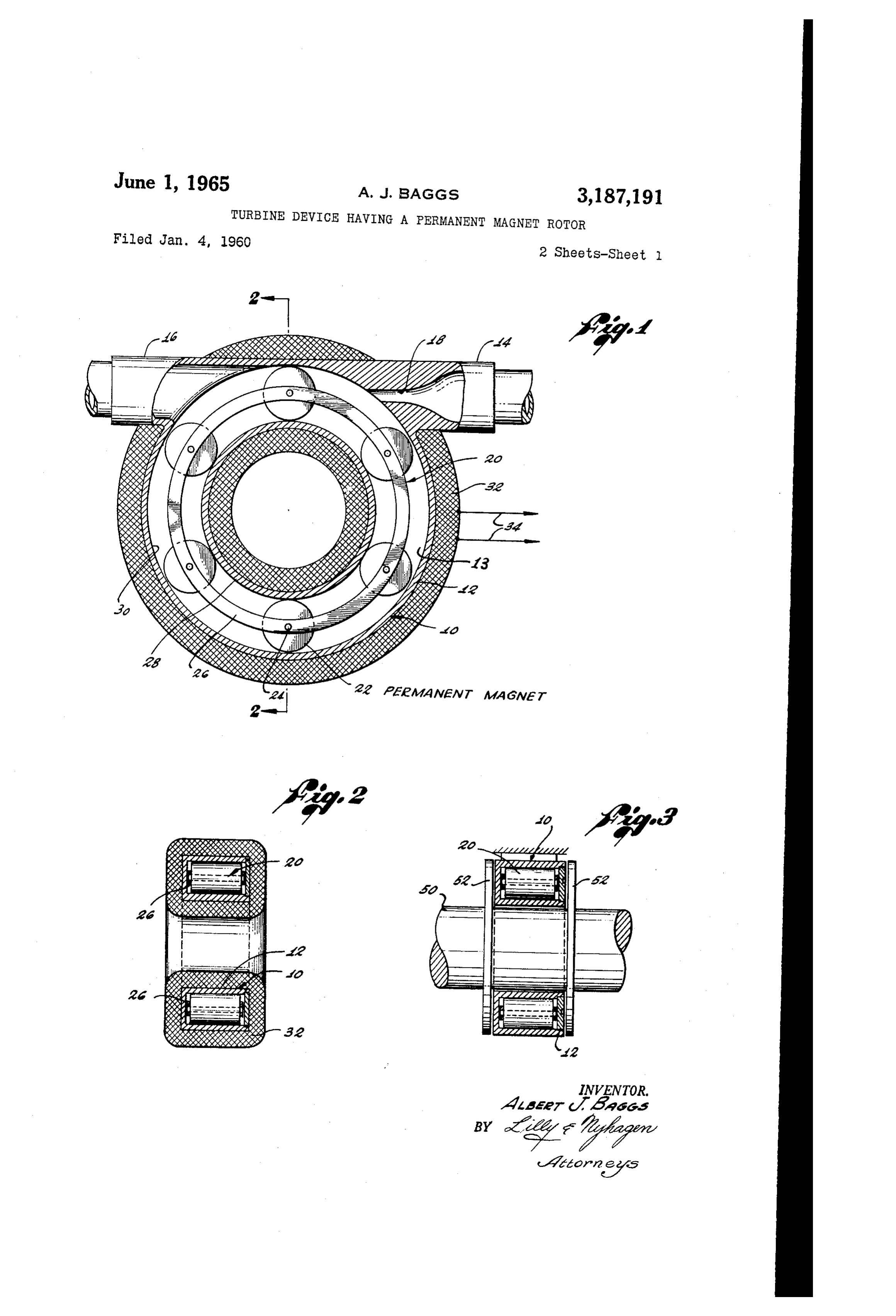
(3929 Yale Ave., Venice, Calif.) In FGS. 1 and 2 of these drawings, the turbine device Fiäed Jan. 4, 1960, Ser. No. 283 of the invention is designated by the numeral 19. This 10 Clairis. (Cf. 290-52) device comprises a hollow, hermetic casing 2 of gen This invention deals generally with fluid pressure op erally 13 in annular or toroidal shape having an interior space the form of a closed loop. The housing has a erated devices and particularly with a unique turbine 10 fluid inlet device. 4 and a fluid outlet 56. Extending through A general object of the invention is to provide a the inlet 4 is a fluid passage terminating in a tangen tially directed nozzle 8.
turbine device which is devoid of shaft seals or other points of fluid leakage and which has an unusual toroidal rotor Rotatably mounted within the turbine casing 2 is the shape that adapts the turbine device to a wide variety 5 prises or impeller 28. This impeller illustratively com of unique uses and applications. a plurality of rollers 22 which are rotatably mount Another object of the invention is to provide several in ed on axles 24. Opposite ends of these axles are fixed different fluid pressure operated devices, each embody lersa are pair of flat rings Žá in such locations that the rol uniformly spaced around the rings, as shown.
ing the present turbine device, namely, a generator to The rollers 22 roll on the inner cylindric surface 28 of produce a rotating magnetic field, an electrical generator, 20 the turbine casing a rotary magnetic drive, a magnetic separator, and a cylindric surface 30and are spaced slightly from the outer of the casing, as shown.
gyroscopic device.
Other objects of the invention are concerned with The turbine device is operated by connecting the fluid providing a turbine device which is relatively simple, inlet of the turbine casing to a source, not shown, of fluid under pressure. This fluid discharges as a high inexpensive, easy to manufacture, and ideally suited to 25 velocity jet through the nozzle 18 and impinges the rol use in nuclear power systems and other fluid systems lers 22 on the impeller which serve as impeller vanes which must be completely closed and leakproof. or blades. The impeller is thereby driven in rotation. Briefly, these objects are attained by providing a tur It is obvious that the impeller 28 can be made in bine device equipped with a hermetic casing of annular ways or toroidal configuration. The rotor of the turbine also peller other than that iliustrated. For example, the im might comprise a ring which is formed with con has a generally annular configuration and is rotatably ventional impeller blades and is retatably mounted in the mounted within the annular interior of the turbine cas ing. Driving of the rotor is accomplished in the usual trated casing by means of ball bearings. Also, while the illus way by the action of pressure fluid on surfaces or vanes dent that turbine device is of the impulse type, it is evi of the rotor. the invention could be embodied in a reaction 35 type turbine as well.
In certain illustrative forms of the invention, the rotor In FIGS. 1 and 2, as well as in FGS. 3-5 to be carries magnetic field producing means, such as permanent presently discussed, the turbine device is utilized to gen magnets, so that a rotating magnetic field is thereby erate a rotating generated during operation of the turbine. In one ii impeller carries magnetic field. For this purpose, the iustrative application, this rotating field is used to gen 40 magnetic field thatmagnetic elements which produce a rotates as the impeller turns. Vari erate electrical power by placing a coil or winding on ous types of magnetic the turbine casing. in other illustrative applications, used for this purpose. field producing means may be the rotating magnetic field acts on a magnetically per neable, rotary driven nember, concentrically arranged rollers in the drawings, for instance, the impeller vanes or in the center opening of the toroidal shaped turbine cas casing 22 comprise permanent magnets. The turbine ing, whereby the driven member is magnetically coupled netically82,permeable on the other hand, comprises some non-mag to and driven from the turbine rotor. In yet another turbine, therefore, thematerial. i Giring operation of the iliustrative application, the rotating magnetic field is em rotation and produces magnetic impeller 28 is driven in a rotating magnetic field.
ployed as ferous ore.
a means to separate ferrous ore from non in FIGS. 1 and 2, this rotating magnetic field is used According to a further illustrative form of the inven to generate an electrical voltage. This is accomplished by placing an electrical winding 32 about the turbine tion, the turbine rotor provides simply a rotating mass for stabilizing purposes. casing A2 in such a way that during rotation of the A. better understanding of the invention may be had impeller, the lines of magnetic force in the rotating from the following detailed description thereof taken magnetic field created by the rotating impeller cut through. in connection with the annexed drawings, wherein: the turns of the coil 32 to generate a voltage across the F.G. 1 is a section through the eiectrical generator output leads 34 of the winding.
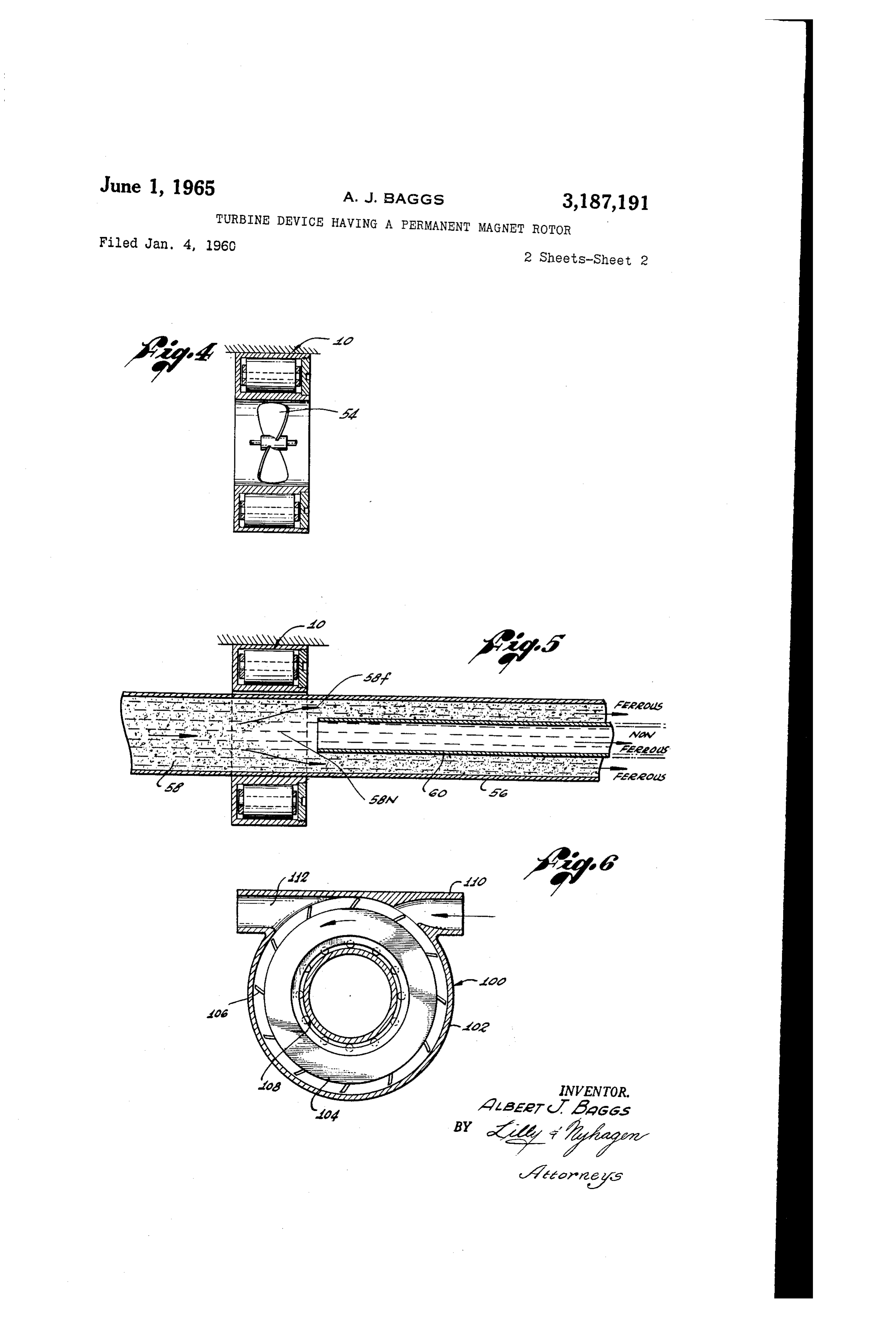
of the invention which embodies the present toroidal An obvious advantage of this unique magnetic tur turbine device; , ' ' . ." bine generator is the absence of any shaft seals or other FiG. 2 is a section, on reduced scale, taken on line 60 points of fluid leakage. This permits a completely closed 2-2 of FIG. 1; fluid system which is highly desirable or essential in many FIG. 3 is a section, on reduced scale, through C}}he. installations, such as nuclear power installations. Also, form of magnetic drive according to the invention; of course, the absence of shaft seals simplifies and re FIG. 4 is a section through another magnetic drive duces the cost of the generator.
according to the invention; 65 in the magnetic drive of FiG. 3, the coil 32 of Fig. 1
Page 4
is omitted. A shaft 58 to be driven is inserted through so as to produce a rotating magnetic field as the impeller the center of the turbine casing A2 and is rotatably tUrlS.
supported in any convenient way, not shown. The tur 2. A turbine device comprising a hollow, generally bine casing 12 itself is fixed. toroidal turbine casing defining an annular space Within Fixedly mounted on the driven shaft 50 at opposite 5 the casing and an axial opening at the center of the cas sides of the turbine casing A2 are a pair of magnetically ing, a rotary annular impeller in said casing including a permeable plates 52. When the impeller 20 of the tur plurality of circumferentially spaced, axially extending bine device i () is driven in rotation, as described in con rollers which roll on an inner cylindric surface of the cas nection with the generator of FIG. 1, the action of the ing, and means to direct a fluid against Said rollers to rotating magnetic field on the plates 52 creates a torque O drive the impeller in rotation. which drives the shaft 5i. It is evident that the magneti 3. The subject matter of claim 2 wherein said rollers cally permeable driven means 52 may assume configura comprise magnetic means to produce a rotating magnetic tions other than plates and may, in Some cases, even com field as the impeller turns. prise the shaft itself. 4. The subject matter of claim including a coil means In the magnetic drive of FIG. 4, the driven member on said casing in which said rotating magnetic field gen comprises a propeller or fan 54 rotatably mounted con erates a voitage.
centrically within the turbine device 26. The blades of 5. The subject matter of claim including a magneti the propeller are magnetically permeable or carry mag cally permeable driven member rotatably mounted con netically permeable means so that the Totating magnetic centrically within said opening through the casing and field produced during operation of turbine 15 creates a 20 driven in rotation by said rotating magnetic field. torque for driving the propeller in rotation. The pro 6. The subject matter of claim including a conduit peller drive of FIG. 4 might be advantageous in wind extending through said opening in the turbine casing, tunnels, for example, because of the absence of a motor and a second conduit extending concentrically through on the axis of the propeller which would disturb the air the first conduit and having an open end located within flow pattern through the propeller as well as restrict air the zone of said rotating magnetic field. foW. 7. A turbine device comprising a hollow, generally In the magnetic separator of FEG. 5, a pipe or conduit toroidal turbine casing having a central axial opening and 56, for conveying ferrcus and non-ferrous material 58 to an internal annular space surrounding said opening, Said be separated, extends through the center of the turbine casing including an internal coaxial Surface forming an ax 59. The material 58 might comprise, for example, a pulp 30 ial wall of said space, an annular impeller in said space in made up of ferrous and non-ferrous ores which is forced cluding rollers engaging said surface to support said im to flow, in some way, through the pipe 55 in the direction peller for rotation in said casing, and means for directing indicated. During movement of this pulp through the a fluid against said impeller to drive the latter in rotation. rotating magnetic field produced by the turbine it, the 8. A turbine device comprising a hollow, generally ferrous materials tend to be formed by the field into a toroidal turbine casing having a central axial opening rotating annular mass 58f adjacent the wall of the pipe 56 therethrough and a toroidal interior space encircling said while the non-ferrous materials tend to be formed into a axial opening, said interior space being bounded at its cylindrical mass 53n at the center of the pipe. radially inner side by an inner, generally cylindrical Wall Extending concentrically through pipe 56 is an inner of said casing extending about and defining the Wall of pipe 69. The left end of this inner pipe is open and 40 said axial opening, at its radially outer side by an Outer, arranged to receive the non-ferrous materials 5&n while generally cylindrical wall of said casing, and at its two the latter are still retained in a concentrated mass by the remaining sides by generally annular side walls of Said action of the rotating magnetic field. The outer annular casing which are joined about their inner circumference mass 58f of ferrous materials flows into the annular space to said inner wall and about their outer circumference to between the inner and outer pipes. The ferrous and non said outer wall, whereby said toroidal interior space is ferrous materials are thereby separated and may be con completely enciosed on all sides by the turbine casing, veyed to separate receivers. impeller means within said interior space and supported In FIG. 6, the numeral EC-9 denotes a turbine device by said casing for rotation around Said space and about having a toroidal-shaped casing E82 similar to the casing said axial opening, said impeller means having impeller of turbine 10. Within this casing is an impeller 104 com surfaces, means on said casing defining a fluid inlet ter prising an annular flywheel having peripheral blades or minating in a nozzle opening generally tangentially to vanes 85. The impeller is rotatably mounted in the cas said space for directing a high velocity fluid stream against ing in some convenient way, such as by ball bearings 163. said impeller surfaces for driving said impeller means in The turbine casing has a fluid inlet lie and a fluid out rotation around said interior space, means on said casing let A 2, like those of turbine 169 so that the impeller is defining a fluid outlet from said interior space, driven driven in rotation by the action of pressure fluid, entering means rotatably mounted within said axial opening, and through inlet 1560, on the impeller blades 66. This ro one of Said means comprising a magnetically permeable tating impeller provides a rotating mass which can be metal and the other means comprising magnetic means used for stabilizing purposes, for example. Such a sta for forming a magnetic drive coupling between said im bilizing device might be used to advantage in a rocket, 60 peller means and said driven means, whereby said driven for example, in which case parts of the rocket propulsion means is driven in rotation by rotation of said impeller system might conveniently extend through the center open Ži:8.S.
ing through the turbine casing. 9. The Subject matter of claim 8, wherein said driven it should be understood that the several applications means comprises a rotary fluid impeller. of the present turbine device which have been disclosed 10. A turbine device comprising a hollow, generally are meant to be purely illustrative in nature and not to toroidal turbine casing having a central axial opening constitute an exhaustive list of all of the possible uses therethrough and a toroidal interior space encircling said to which the turbine can be put, axial opening, Said interior space being bounded at its What is claimed is: radially inner side by an inner, generally cylindrical wall 1. A magnetic turbine device comprising a hollow, gen O of said casing extending about and defining the wall of erally toroidal turbine casing defining an annular space said axial opening, at its radially outer side by an outer, within the casing and an axial opening at the center of generally cylindrical wall of said casing, and at its two the casing, a rotary annular impeller in the casing, means remaining sides by generally annular side walls of said to direct a fluid against the impeller to drive the latter in casing which are joined about their inner circumference rotation, and magnetic means mounted on the impeller 75 to said inner wall and about their outer circumference
Page 5
to said outer wall, whereby said toroidal interior space is References Cited by the Examiner completely enclosed on all sides by the turbine casing, UNITED STATES PATENTS an annular impeller within said interior space and rotata bly mounted on said casing for rotation around said space 1,307,210 6/19 Newcomb ----------- 290-52 ? and about said axial opening, said impeller having im- 5 2,270,141 1/42 Potter ---------------- 290-52 peller surfaces circumferentially spaced therearound, 2,276,714 3/42 Brown -------------- 290 - 52 ? means on said casing defining a fluid inlet terminating in 2,709,755 5/55 Potter ----------------- 290--52 a nozzle opening generally tangentially to said interior "ZAM IT- o space, and means on said casing defining a fluid outlet ORIS L. RADER, Primary Examiner. from said space. 10 MILTON O. HIRSHFIELD, Examiner.
Provenance
- Collection
- Cited prior art
- Original PDF
- patentimages.storage.googleapis.com →
- Filed
- 1960-01-04
- Pages
- 5
- Method
- pdftotext (the PDF's own text layer) + pdftoppm 300dpi page scans
- Source
- Google Patents bibliographic record
- Granted
- 1965-06-01
- Inventors
- Albert J Baggs
- Transcribed from
- patentimages.storage.googleapis.com →