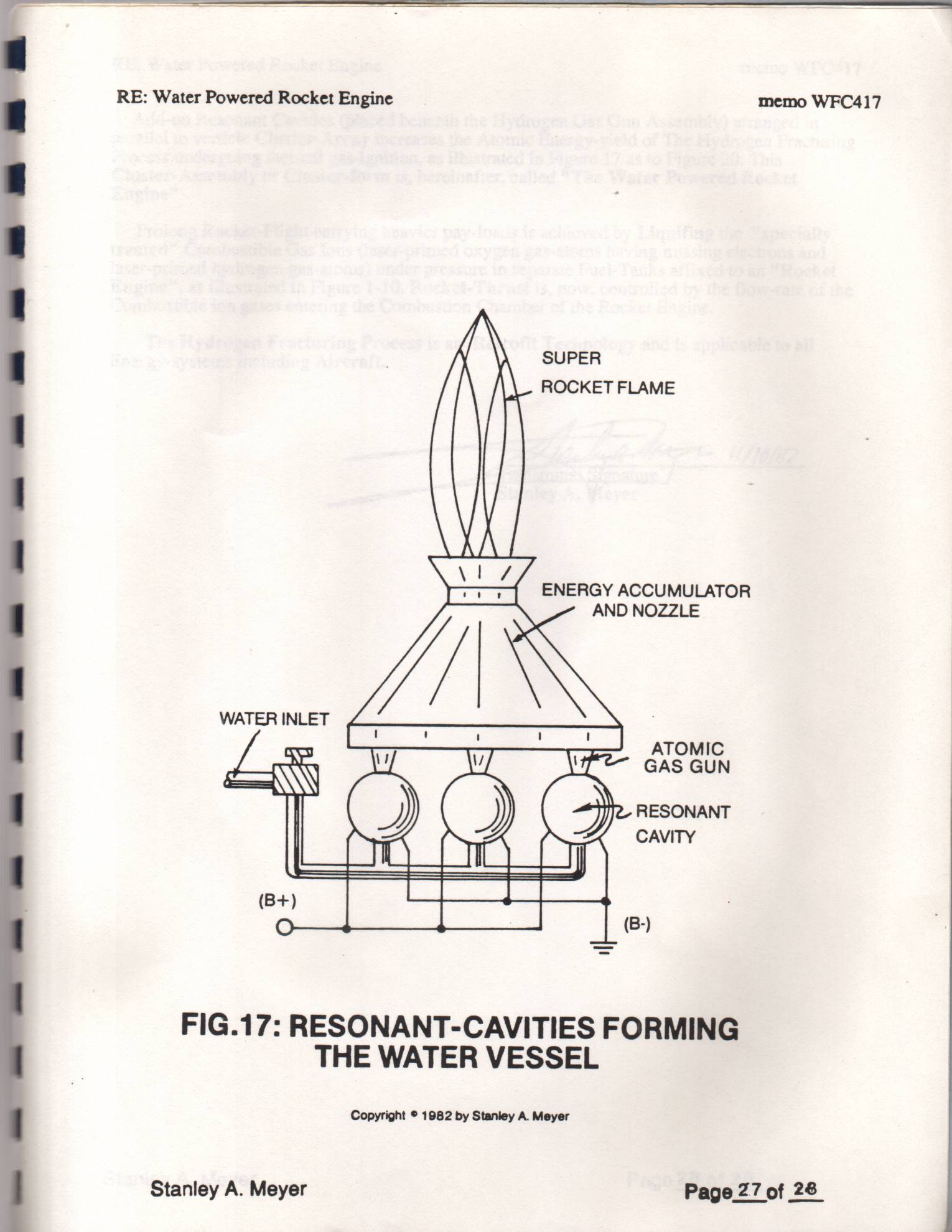
Figure (17)
Resonant-cavities Forming The Water Vessel C
How it is written
- (17) 1× with (17) Pulse width
Drawings 46
-
Stanley A. Meyer Page27 of 28 · WFC 417 — WFC 417
-
Stanley A. Meyer Page_3 of 28 · WFC 417 — WFC 417
-
Stanley A. Meyer Page17 of 28 · WFC 417 — WFC 417
-
Stanley A. Meyer Page 28 of 28° · WFC 417 — WFC 417
-
Carries this number · Figure 9B & 9BB - Applied Voltage To Plates
-
Figure (1-3) · LC Circuit
-
Figure (1-5) · LC Voltage
-
Le is light intensity in watt; T1 is current on-time; T2 is current off-time; and (ION)=RMS value of load current during on-period. · Laser Interaction
-
Resonant Cavity Assembly, as illustrated in Figure (1-17) · Electron Extraction Process
-
Carries this number · Acceleration Control Circuit (30)
-
Toggling action at full-scale deflection (13a xxx 13n) occurs in the range of (10) kHz or above and thus, allows instant response to driver's acceleration demands. · Acceleration Control Circuit (30)
-
Figure (3-13) · Acceleration Control Circuit (30)
-
Figure (3-13) · Acceleration Control Circuit (30)
-
Carries this number · Analog Voltage generator (40)
-
Figure (3-15) · Voltage Amplitude Control Circuit (50)
-
Carries this number · Gated Pulse Frequency generator (80)
-
In terms of assembly, gas resonant cavity (410), electron extraction circuit (270), optical lens (121) forms gas processor (260) of Figure (3-31). · Gas Processor
-
Carries this number · WFC 422DA - Illustrations
-
Carries this number · WFC 422DA - Illustrations
-
Carries this number · WFC 422DA - Illustrations
-
Carries this number · WFC 422DA - Illustrations
-
Carries this number · WFC 422DA - Illustrations
-
Carries this number · Electronic Circuit Design
-
Carries this number · Electronic Circuit Design
-
Carries this number · Electronic Circuit Design
-
Carries this number · Electronic Circuit Design
-
Carries this number · Differential Air-Gas Inlet Control
-
Water Fuel Injection System (10) of Figure (1) · Water Fuel Injector (Taper Resonant Cavity Chamber)
-
Carries this number · Water Fuel Injector (Taper Resonant Cavity Chamber)
-
Figure (17) · Water Fuel Injector (Taper Resonant Cavity Chamber)
-
Carries this number · Funneling Effect
-
(520) of Figure (4-3) · Funneling Effect
-
thereby, attenuating voltage amplitude (voltage intensity) beyond Secondary Coil (53) voltage levels (71), as illustrated in (220) of Figure (18). · Funneling Effect
-
Carries this number · Funneling Effect
-
Figure 1-3 · Amp Inhibiting Circuit Vs Voltage Enhancement
-
Ambient Air Ionizer (Gas Processor) (80) of Figure (4-6) · Water Fuel Injection System - Page 3
-
Carries this number · Energy Pumping Action
-
(520) in Figure (5-3) · Resonant Propagation
-
(520) of Figure (5-3) · In Application of Usage
-
(520) of Figure (5-3) · Solar Energy Actuator
-
Carries this number · Illustrations
-
Hydrogen Fracturing Process (520) of Figure (5-3) · Voltage Intensifier Coil-Assembly
-
(520) of Figure (5-3) · 8-2 - Traveling Voltage Wave-Guides
-
WFC Gas Processor (80) of Figure (1-17) · WFC Development Objectives
-
Energy Pumping Action (520) of Figure (5-3) · WFC Development Objectives
-
When (B+/B+ - B-/B- / 1030B) switch function is activated, switch terminals (T1/T2 - T3/T4) are closed. · Electrical Crossover Switching Circuit
Where it is named · 1
WFC 417 — WFC 417 1×
-
Add-on Resonant Cavities (placed beneath the Hydrogen Gas Gun Assembly) arranged in parallel to verticle Cluster-Array increases the Atomic Energy-yield of The Hydrogen Fracturing Process undergoing thermal gas-ignition, as illustrated in Figure 17 as to Figure 20. This Cluster-Assembly or Cluster-form is, hereinafter, called "The Water Powered Rocket