Chris Hunter "Alaska Star" releases an O U PDF
Started by RAMSET · · 15 posts · last reply 13 May 2014
-
#1 ·
It has been many years since I last Spoke with Chris , he has shared something
truly wonderful.
A truly exemplary Human being.
Enjoy.........
Chet
PS
This was shared By "Mehmet"
at OverunityResearch.com
Link works nowAttached Files -
#2 ·
Hi Chet,
This sounds interesting but I see no link?
Gene -
#3 ·
Excellent!
Chet,
Thanks for posting this. I've worked on a similar set of ideas for years, using air and water as the working fluids, where the air is in an open cycle and the water is re-used over and over.
The front end is essentially an off-the-shelf piston compressor. Ambient air is drawn in and compressed, raising the temperature. This hot, compressed air is pushed into a small reactor chamber just off the piston head. Water is preheated by the input cylinder heat and then injected into the reactor chamber to flash to steam. Next, the valve opens and the compressed air and the expanding steam produce the power stroke in a "steam engine" type wet environment piston (like brass or bronze) with a shorter stroke so the water re-condenses right at the bottom of the stoke. Finally, the exhaust valve opens and the cool air and water are evacuated to be separated and the cycle starts again. The water is recycled but new ambient air is used with each stroke.
The machine is essentially a "solar powered steam engine" that works on the heat in the ambient air for 24/7 operation.
Chris Hunter's design, using LPG in a closed cycle, uses the same basic physics and this document looks to be the description of a real, working system. By using a single refrigerant in both its liquid and gaseous forms, it simplifies the engine design considerably. Is there any way to find out more? Pictures, diagrams, test results? There are people who would fund development of this technology.
I also discuss a variant of this idea published by Nikola Tesla in 1900 in a lecture I gave last summer titled Open System Thermodynamics.
Tesla called his machine the "Self-acting Engine." He believed that the "heat in the ambient air" was the largest, untapped energy source on the planet, and the engine that tapped that source would be the most important engine ever developed for the future of civilization.
Thanks for sharing.
Best regards,
Peter -
#4 ·
Thanks RAMSET, Thanks Chris Hunter!
Thanks RAMSET, Thanks Chris Hunter!
Below is just a copy-paste from pdf (SO ANYONE COULD READ THIS)
FOR FREE THINKING RESEARCHERS ONLY
"REFRIGERANT ENGINE" OR
"AEROTHERMAL ENGINE"- "A.T.E."
AN EXPERIMENTAL GASOLINE ENGINE MODIFICATION.
TURN AN OPEN INTAKE/OPEN EXHAUST HEAT BASED GASOLINE ENGINE INTO A "CLOSED LOOP" COLD REFRIGERANT BASED ENGINE.
THE ULTIMATE ENERGY SOURCE FOR THIS ENGINE IS HEAT.
IN PRACTICAL USE, HEAT IS PROVIDED BY THE SUN, AND IS EXTRACTED IN AN ECONOMICAL FASHION.
EXCESS HEAT ENERGY IS PRESENT IN INEXTINGUISHABLE QUANTITIES ON PLANET EARTH.
CONSTRUCTION
COMMON GASOLINE ENGINE, 2 CYCLE OR 4 CYCLE.
NOTE: 2 CYLINDERS MUST HAVE 180 DEGREE CRANKSHAFT. NO 3 OR 5 CYLINDER ENGINES. NO DIESEL.
1. CONNECT EXHAUST PIPE/TUBE TO INTAKE PIPE/TUBE AT CLOSEST POINTS POSSIBLE, WITHOUT LEAKS, MAKING ENGINE CLOSED LOOP OPERATION.
2. ADD A T-FITTING OR OUTLET CONNECTION TO THE EXHAUST/INTAKE LOOP, PREFERABLY NEARER THE EXHAUST MANIFOLD.
3. ADD A ONE WAY CHECK VALVE AT THE EXIT OF THE T-FITTING/CONNECTION. CHECK VALVE EXAMPLE- PARKER PNEUMATIC
VALVE OPENS AT 5-7 PSI (11 PSI MAXIMUM).
4. BEYOND THE CHECK VALVE, ADD A BALL VALVE TO REGULATE FLOW.
5. BEYOND CHECK VALVE/BALL VALVE ASSEMBLY, CONTINUE PIPE/TUBE TO INLET SIDE OF AN AIR CONDITIONING PUMP, THAT IS IN OPERATING CONDITION, AND ALREADY ATTACHED TO THE ENGINE.
6. OUTLET OF THE AIR CONDITIONING PUMP GOES THROUGH ONE OR MORE CONDENSER COILS, AND THEN TO A SMALL ACCUMULATOR ABOVE THE FUEL INJECTOR, WHICH IS MENTIONED LATER. CONDENSER MUST BE COOLED BY FAN AND/OR AIRFLOW.
7. REMOVE SPARK PLUG(S). MAKE AN ADAPTER TO INSTALL AN LPG/PROPANE
TYPE FUEL INJECTOR INTO SPARK PLUG OPENING. REPLACE SPARK PLUG WITH LPG/PROPANE INJECTOR ONLY. GASOLINE TYPE INJECTOR WILL NOT WORK. FUEL INJECTOR EXAMPLE- MOTORCRAFT PART #CM5153, FORD TRUCK WITH LPG.
8. THE FUEL INJECTOR IS FIRED AT TOP DEAD CENTER (TDC) AFTER COMPRESSION STROKE, AND REMAINS OPEN FOR APPROXIMATELY 90 DEGREES (THIS MAY VARY BY APPLICATION). A SMALL BALL VALVE ABOVE THE INJECTOR MAY REGULATE RPM/ENGINE SPEED.
9. CHARGE SYSTEM AS TYPICAL FOR AC SYSTEMS USING R12a REFRIGERANT, OR LESS FLAMMABLE PROPANE/LPG. CHARGE TO 3-7 PSI. DO NOT EXCEED 11 PSI.
10. ENGINE WILL RUN COLD. USE 5-20W
MOTOR OIL, 0-20W IN COOLER CLIMATES. REMOVE THERMOSTAT, OR REMOVE CENTER OF THERMOSTAT (DEPENDING ON APPLICATION).
11. REGULATING ENGINE SPEED AND TIMING PRESENT A CHALLENGE. MULTIPLE CAMSHAFT TRIGGERS MAY PROVIDE A GOOD WAY TO "TIME" THE LPG INJECTOR. A PWM CIRCUIT MAY BE USED WITH A VARIABLE RESISTER TO CONTROL ENGINE SPEED. MAYBE A SMALL ELECTRIC MOTOR AND SET OF POINTS AND VARIABLE RESISTER (5 OHM). MAYBE MANUAL BALL VALVES TO REGULATE FLOW.
12. COULD IT BE SIMPLER THAN THAT?
EFFECT
THE INTAKE PLENUM IS PRESSURIZED TO A
MINIMUM 3.0 PSI
THE INTAKE STROKE HAPPENS. CYLINDER COMPLETELY FILLED WITH REFRIGERANT.
THE INTAKE VALVE CLOSES.
THE PISTON MOVES FROM BOTTOM (BDC) UPWARD AND COMPRESSES THE REFRIGERANT.
AT THE POINT WHERE THE PISTON REACHES TOP OF THE CYLINDER AND THE REFRIGERANT HAS REACHED MAXIMUM COMPRESSION PRESSURE, THE LPG INJECTOR THAT IS IN THE SPARK PLUG OPENING "OPENS" AND SPRAYS A SMALL BIT OF LIQUID REFRIGERANT INTO THE CYLINDER.
THIS REFRIGERANT BEGINS TO EXPAND IN THE HOT PRESSURIZED REFRIGERANT IN
THE CYLINDER, PUSHING THE PISTON DOWN, GENERATING HORSEPOWER AND TORQUE.
AT THE POINT THAT THE PISTON REACHES THE BOTTOM OF ITS POWER STROKE AND BEGINS TO RETURN UPWARD, THE EXHAUST VALVE OPENS AND THE PISTON PUSHES THE NOW EXPANDED REFRIGERANT OUT OF THE CYLINDER PAST THE EXHAUST VALVE INTO THE COMMON LOOP MANIFOLD.
HEAT ENERGY FROM FRICTION, COMPRESSION, AND ATMOSPHERIC HEAT WORK TOGETHER AS THE READILY AVAILABLE FUEL.
GASOLINE IS ALSO A HEAT FUEL. WHEN GASOLINE BURNS, THE HEAT PRODUCED CAUSES ATMOSPHERIC GASES LIKE
NITROGEN TO RAPIDLY EXPAND, PUSHING THE PISTON DOWN.
RATHER THAN USE GASOLINE, WHICH PRODUCES HUGE QUANTITIES OF HEAT THAT IS NEVER USED FOR POWER (BUT IS WASTED), WE MAY USE READILY AVAILABLE HEAT WITHOUT ANY WASTE OR TOXIC BY-PRODUCT.
THIS DISCOVERY WAS MADE BY A BRILLIANT YOUNG SCIENTIST AND INVENTOR- CHRIS HUNTER, OF FAIRBANKS, ALASKA.
MR. HUNTER WORKED FOR 9 YEARS, SPENDING LARGE SUMS OF HIS OWN MONEY TO COMPLETE THIS SYSTEM.
MR. HUNTER HAS OPENLY SHARED ALL OF HIS
DISCOVERIES WITH MANKIND.
MR. HUNTERS KNOWLEDGE AND EXPERIENCE ARE UNSURPASSED, IN MY OPINION. HE IS AN EXPERT MECHANIC, AND HAS WORKED WITH TURBINES, QUASI-TURBINES, WANKEL, SCROLL EXPANDERS, TESLA TURBINE, STEAM ENGINES, 2 STROKE BASH VALVE, HHO WATER FUEL, EXOTIC ELECTRIC MOTORS, AND THE LIST GOES ON.
THANK YOU MR. CHRIS HUNTER.
180 DEGREES CRANKS:
[IMG]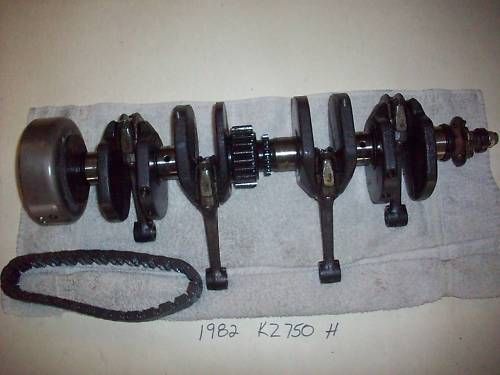 [/IMG]
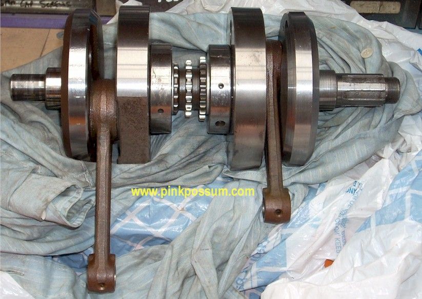
Above are Motorcycles engines crankshafts...
This Engine should work perfectly...and is very low psi...not even an HVLP (High Volume Low Pressure) Spray Gun works this low pressure, but at seven(7) or 9 psi...
"Air Conditioning Pump" he means an AC Compressor, and the "Inlet" is the Low Pressure/Suction Line (he recommends to keep it closer to Exhaust Pipes)...Outlet or Discharge Line (High Pressure Side) goes to the Condensers and the SMALL Accumulator (Drier) Bottle (all this are automotive AC Parts) He says accumulator to be above fuel injectors...
One thing that I notice, is missing to be explained here (as I see this whole thing already) is the distribution from the high pressure line from accumulator to a "DISTRIBUTOR" Type Pump (similar to a Diesel Fuel Pump), and then to each individual Propane Injectors installed at each spark plug housing...and they should work with a Timing with each cylinder following and starting by TDC on #1
I really see no need to "fund" this type of making/replication...just a nice shop and some good mechanic(s) (also an AC guy)could convert this engines in a few days...parts available though.
This Engines could be rebuild to even better spec's...junk yards, etc,etc
A completely looped engine...beautiful!
I will make some diagrams and share them here.
Kind Regards
Ufopolitics -
#5 ·
Thanks Chet, Ufo
Gene -
#6 ·
Contact
Gents
I will try to call Chris for more info/details .
I see UFO post below ,I believe Chris has a variable Pulse fire system /Mod in mind for timing.
Here is an example of some unrelated work he has been doing
http://peswiki.com/index.php/Directory:ArcticTek:Chris_Hunter_(Alaska_Star)'s_A xial_Flux_Motor
Thx
Chet -
#7 ·
-
#8 ·
more to come.........
I am corresponding with Chris
I have invited him to assist.
Will keep you posted.
thx
Chet -
#9 ·
Oh!, that is awesome Chet!
Hello RAMSET,RAMSET wrote:
I am corresponding with Chris
I have invited him to assist.
Will keep you posted.
thx
Chet
Oh that is awesome Chet!
But I must admit I was wrong in my interpretation of his pdf...since I was not familiar with Liquid Propane Injectors...and they do have an open/close electronic switch, just like a Fuel Injector does...so, there was no "missing" explanation from his end...it is obvious the AC Compressor outlet goes to the Condensers then to Accumulator, then to Injectors Bank Main Line.
Then I realize why Chris mentions PWM or an electric motor to control sync/timing to Fire each injector in bank according to the typical engine fire order.
Awesome, I love this project, and so many thanks to you and to Chris for doing this!
I called my Ford parts guy...and FORD does not sell any Propane parts...so, this is "aftermarket" stuff...
The Motorcraft CM5153 that Chris is referring to:
[IMG]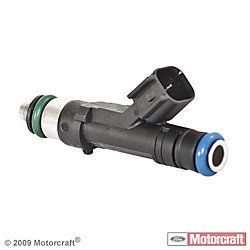 [/IMG]
Is a typical FORD 5.4 Liters/Econoline Gasoline Fuel Injector...and that is NOT good.
The ones to use are:
[IMG]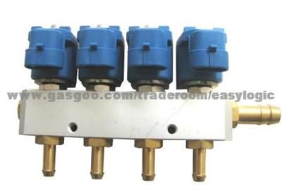 [/IMG]
LPG Injector Kit
Therefore, all misunderstandings are gone now...
Kind Regards Friend
Ufopolitics -
#10 ·
A few questions on "bar"
UFO
yes the PDF does cover that ,however a few questions have come up from Graham at Overunityresearch [thread being settup] on Pressure in the system and how it may apply to the design parameters of the mentioned injectors operating range.[back pressure]
Graham scratch builds ICE's in the UK,but like most of us is unfamiliar with
Chris's unique thoughts and hands on experience with this type system.
We gonna learn...........
Thx for your contribution,and for the record I am just a grateful messenger
completely dedicated to assisting true open source get out to the world
[like most here ]
This is Chris's legacy to the world [along with those who helped him]
more to come
thx
Chet -
#11 ·
-
#12 ·
Takes temperature
"Z"
Water becomes useful for combustion when high Temperature forces
stoichiometric state [or other methods]... as Johan_1955 has shared.
Yes we are getting much closer to the place we should have been 100 years ago
Chris has just given Us a nice reminder..........
a truly gifted young man with Many wonderful ideas for "efficiency" in modern times.
thx
Chet -
#13 ·
Nope, this is NOT!
Hello ZMI,
Sorry to tell you but "this ain't copy paste from anything else I have seen"...so far before.
Here there are absolutely "NO TANKS" to fill out...No HHO tank, No Water Tank, no fuel nor gas tanks...as also no "Exhaust Pipes"...so, nothing to fart...
Intake and Exhaust are on a closed loop, friend.
This time we will convert the farting obsolete machines to a closed loop...where they will literally "eat/swallow/inhale" a cleaner, better smelling fart, just a bit hot...
Regards
Ufopolitics -
#14 ·
Great question...
Hello RAMSET,RAMSET wrote:
UFO
yes the PDF does cover that ,however a few questions have come up from Graham at Overunityresearch [thread being settup] on Pressure in the system and how it may apply to the design parameters of the mentioned injectors operating range.[back pressure]
Like Chris mentioned, the operating pressure is low...and the max is at 11 psi.
Also-as He said- every engine has different capacities/spec's in litters (US) and this has to do with the Vacuum Pressure each piston would effect at suction time into the whole system. So, every Engine Capacity needs to be filled out with refrigerant til reaching this number...and not all will take same amounts.
What I see on this, is to set a pressure gauge on Injectors Main Bar, then watch while running at idle, then observe how pressure comes down when slow acceleration starts. If engine starts stalling when acceleration...then we need to increase pressure to prevent "stalling from starvation" by either opening more the supply valve closer to exhaust to AC Compressor Inlet (low pressure), or the one Chris recommend at Injectors level (High Pressure)...if this does not work...then we need to fill the System with more Refrigerant.
This kind of testing would have to be done on each individual Engine as a final touch "Stand Tune-Up"...then later on while mounted on vehicle and standing the braking of the inertia forces load on accel.
Well Chet, "unfortunately", I am pretty familiar with this stinking engines...Graham scratch builds ICE's in the UK,but like most of us is unfamiliar with
Chris's unique thoughts and hands on experience with this type system.
We gonna learn...........
Thx for your contribution,and for the record I am just a grateful messenger
completely dedicated to assisting true open source get out to the world
[like most here ]
This is Chris's legacy to the world [along with those who helped him]
more to come
thx
Chet, Unfortunately I said...cause I hate to get my hands very black greasy working on many Diesels, Turbo-Diesels, Gas, Pumps, whole engines rebuilding (as a hobbyist though)...and High Performance Racing stuff...so, I believe I could throw some ideas as well as understanding of the whole new concept Chris and You are showing here.
EDIT 1: On a separate note about "pressure":
Each Engine have their own specific cylinder compression values...we must know that...in order to "rate" all Injector Valves and Hosing to be installed, to stand direct pressure from strokes at the Intake Plenum levels. Adding the wrong LPG Injector pressure range could blow them up in first run...and refrigerant is not cheap.
One of the things that must be done, like in any AC System, is to run a heavy EXTERNAL Vacuum Pumping through regular AC recharging High/Low Pressure connectors to check system for leaks (if not maintaining steady measurements) and to test vacuum pressure (back pressure) capabilities.
We could regulate flow/pressure later on "electronically" through "AC Expansion Valves" set at each strategic points.
Regards
Ufopolitics -
#15 ·
Sounds interesting, the perfect motor would be from a motorcycle as mentioned above you can find 2 4 and 6 cylinder version, Honda makes an opposed 6 cyl for their 1800cc motors (Goldwing). find one of those and you should have what you need for a car or generator.


Sign in to reply, or ask for an account.