I have watch the video on youtube as indicated on h2-global website but I can't see any working device with this new technology. Can you indicate me an video that present an working prototype? Regards
tutanka
25 posts · 1 thread started · 53 more in threads this archive does not carry · writing between Feb 2010 and Aug 2017
An identity on Energetic Forum as it was harvested, not an account on this site. Nobody here has claimed it, and nothing connects it to a person by name.
Hello to all ..
CO2 DISSOCIATION IS OVER...
CO2 DISSOCIATION IS OVER...
Attached Files
Aaron wrote:
A video of that was shown as part of my presentation at the 2014 conference. The demo of that jet was given to a couple angel funders. I might put that segment on youtube at a later time. It is about 8 minutes long and was never intended to be shown to the public.
RAMSET wrote:
Tutanka
sure
The TinMan is a regular spielberg with the Movies
I will post them as they come.
You bring the Popcorn...
thx
Chet

RAMSET wrote:
Note. the system has been run with out any HHO for the last year ,but engine damage was a problem [long term testing]
recently HHO has been added to The fuel mix.
this is the simple yet effective test protocol
Brad
quote
ATM we are useing 20% gasoline,10% catalyst,and 70% water-->with the addition of the 7LPM of HHO.
The catalyst is to remain with me and my partner ATM,but the rest of the system is of course -open source.
Our test method ATM
Our load is a string of incandecent party lights that places around a 600 watt load on the generator.We simply measure the voltage across the light string so as to maintain the same load throughout the testing.The engine is also goverened,so speed remains constant.
We first run the unit on straight gasoline,and use a set volume of 200mL. We simply time each run,and record the result's.We then add the 700mL of water,and 100mL of catalyst to the gasoline,and run the test again,with the HHO as well of course.To achieve the 240 volts needed from the 24 volt altinator,we simply use a 24 v to 240 v inverter-->in this case,a UPS,so as we get a true sine wave output.
We are still working on getting the gasoline ratio down even further,but at this time it seems we have reached the limit with the materials and funds we have at hand.
Aaron wrote:
Ditto on the catalyst comment Dog-One - if there is one significant thing like that left out...
If they use plasma ignition on the generator, they can lean it out even more.
My jet engine runs on tap water with a small trace amount of propane and that is without even using HHO on it yet. I began with 8psi of a certain flow rate of propane to run it and by the time I was done with exhaust recycling, plasma, etc..., the propane psi gauge is at 0 psi because it uses so little that gauge can't read it. My guess is about 90% tap water and about 10% propane if even that much.
Mark McKay was kind enough to give me a couple flow meters that look accurate enough to measure the actual flow at that low level so I'll measure it when I have time, but cutting it from 8psi to 0psi (on the gauge) is quite a cut.
The jet runs so efficiently, I can put my hand about 3 feet from the exhaust and keep it there it is so cool running.
RAMSET wrote:
Well
I was waiting till monday to call...However
it seems they have not setup their answering machine yet.
??
of course I will report all findings.
That was the first one
thx
Chet
Fake!!!
The fake generator work in this way....
The first battery is associated with an inverter and power an resistor for make steam inside the water tank , the steam run an motor that is connected to the generator and the little generator charge just one battery , I suppose 12V 100-125Ah, that is connected to an 3kw inverter. There are two inverters and two batteries inside the generator. Water is used just for make the steam!!! The man do no use more load like an electric stove because for me can't work. Of course you can use 3Kw but just for an very limited time. Is completely different from an standard gasoline generator. The water isn't used as an fuel!! To the end who recharge the first battery used as the real source of energy?? In other words do not buy it!!!
The fake generator work in this way....
The first battery is associated with an inverter and power an resistor for make steam inside the water tank , the steam run an motor that is connected to the generator and the little generator charge just one battery , I suppose 12V 100-125Ah, that is connected to an 3kw inverter. There are two inverters and two batteries inside the generator. Water is used just for make the steam!!! The man do no use more load like an electric stove because for me can't work. Of course you can use 3Kw but just for an very limited time. Is completely different from an standard gasoline generator. The water isn't used as an fuel!! To the end who recharge the first battery used as the real source of energy?? In other words do not buy it!!!
Attached Files
PhysicsProf wrote:
I'm very interested in understanding anomalous heat production in light water (H2O) experiments - and the history of research in this area.
(Light water anomalous heat -- as opposed to claims of "cold fusion", now "LENR = Low Energy NUCLEAR Reactions", in heavy water = D2O... Yes, there are SMALL LENR effects (not Quantitatively correlated with excess heat production ) -- but I hypothesize that these represent a distinct phenomenon from the excess heat (using D2O or deuterium) claims.)
Steven Jones replica: Pons & Fleischmann XS Heat not from fusion
I'll be going to the ICCF-18 conference in two weeks at Univ of Missouri... My hypothesis is that what Pons&F saw in heavy water, excess heat they claimed was due to "cold fusion" -- was not fusion and probably was not even NUCLEAR in origin at all; that they would have seen the same effects in LIGHT WATER H2O if they had pursued this sufficiently. It is best to call it, an "unknown source of energy".
I've traced light-water energy-production claims as far as Peter Davey of New Zealand, who rec'd a NZ patent for his H2O device in about 1945. The Davey-bell apparatus is quite interesting, and I have presented some experimental results from my own studies of Davey-type devices.
But I'd like to find out about others who have contributed to light-water energy research - and WHEN they did the research.
Michael Nunnerley -- told me that his researches in this area began in 1989, independent of Pons&F.)
Dr. Ronald Stiffler did electrolysis work in light water -- when did his researches in this area begin?
Stanley Meyer -- did any of his work involve electrolysis? not that electrolysis is REQUIRED for H2O-anomalous heat... Also, when did he begin his studies of energy production in light water?
Keeley? I don't know much about what he did with water, but would like to learn.
Rossi also Defkalion -- both claim energy (heat) production with light water; when did their researches begin?
Any pointers in this area would be appreciated.
AIR + WATER + SUN= Energy
Stan Meyer have understand, after some time, that these elements are connected togheter.
Water Fuel Secrets
#3 ·
Air Not Just Nitrogen..
Today I have received an email from Aaron mailing list about the new book based on Meyer works and on nitrogen..
Reading these posts I have decided to reply for to have an clear vision on that.
Meyer do not use just nitrogen but air (oxygen and nitrogen) and do not produce another molecule as ammonia during the process but just an atomic reaction , initially inside engine after inside the wfc injector.
Is important understand that Meyer has found casually (or maybe in contact with others inventors) that an special air treatment can be used as fuel.
From my side, after I made some experiments in this direction and writing two patents, I understand that Stanley Meyer don't has clear completely the right process.
I want open your minds!!
We are born in petrol era and we have been educated to burn gasoline and think that air is only an oxydant.
I can assure that need to be revised this concept because Isn't TRUE!!
I published an my video on http://www.air4gas.com
Today I have received an email from Aaron mailing list about the new book based on Meyer works and on nitrogen..
Reading these posts I have decided to reply for to have an clear vision on that.
Meyer do not use just nitrogen but air (oxygen and nitrogen) and do not produce another molecule as ammonia during the process but just an atomic reaction , initially inside engine after inside the wfc injector.
Is important understand that Meyer has found casually (or maybe in contact with others inventors) that an special air treatment can be used as fuel.
From my side, after I made some experiments in this direction and writing two patents, I understand that Stanley Meyer don't has clear completely the right process.
I want open your minds!!
We are born in petrol era and we have been educated to burn gasoline and think that air is only an oxydant.
I can assure that need to be revised this concept because Isn't TRUE!!
I published an my video on http://www.air4gas.com
air can be ignited...
Air can be ignited simply respecting simple conditions. I have tested this condition in my latest reactor and the air is transformed in gas and is burned at the same time.
Air can be ignited simply respecting simple conditions. I have tested this condition in my latest reactor and the air is transformed in gas and is burned at the same time.
3D electromagnetic field
#12 ·
MonsieurM wrote:
I just had a quick look ...I read about it before here
Robert T. HART
EH Antenna
Robert hart -- EH Antenna
will definitely look into it
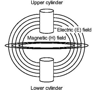

Using that method you can process your water molecules in the middle of EM field and obtain in output your gas , that semplify previously method but my question is you obtain an high efficiency >90% during the reaction?
Im not sure of that because during my test the variable of time inside process is very important.
an advanced solution
Instead that is advanced solution based on Gray tube, you can use every HV diode and MOT transformer that you can found inside an microwave oven
Instead that is advanced solution based on Gray tube, you can use every HV diode and MOT transformer that you can found inside an microwave oven
an other solution..
Hello,
That can be other solution, you can use low cost microwave oven parts and build an home generator or an tesla transmitter. You can use the same circuit in reverse mode as receiver. Regards
Hello,
That can be other solution, you can use low cost microwave oven parts and build an home generator or an tesla transmitter. You can use the same circuit in reverse mode as receiver. Regards
HHO LED Driver
#4 ·
ibpointless2 wrote:
Ran it all night. The battery went from 8.41 to 8.38, not bad becuase it gave off a good amount of light.
Now for the bad, the magnets won't work, you need stainless steel or gold magnets. I can't tell you how much HHO was produced but it can't be much, but it was constant small bubbles when i went to sleep.
I've got to find the resistance of the water so that i can make some resistor like it to run a LED off a 9 volt. It could run for a long time.
HHO LED Driver
#2 ·
ibpointless2 wrote:
I've got something, still in the early testing phase, a unique thing. Its very simple idea, a battery and two electrodes make HHO. But thats been done before so i spiced it up a bit.
I got a 9 volt battery with 8.41 volts on it and its running a LED, and producing what i assume is HHO at the same time. The setup is simple, the positive of the battery goes to a stack of round neo magnets and about 1 inch from that you got the positive of a LED in the water and the negative of the LED goes back to the battery. Small bubbles form on the positive of the LED and the LED lights up too. What is interesting is that battery has been at 8.41 volts for about a hour.
The reason for this idea started out with me thinking, could you make a HHO generator with two different metals? just like how a water battery works i thought the same principle could be applied and give great power to the HHO generators out their. so testing out metal i used the leads of a LED and to my amazement the LED lit up. Not really amazing when you consider the water acts like a resistor and thats why the led continues to light. But even with my control experiment i used a 1k ohm resistor with another 9 volt to see how long it would hold the charge, the resistor one drop in voltage while the water one didn't. I thought the HHO was a added bonus too.
It could be nothing but i figure i should let others know about it because you never know, it could spark a great idea from somebody.
I used just regular tap water.
[ATTACH]6876[/ATTACH]
 Can you post an photo when system running? Thanks
sebosfato wrote:
Hello,
I tried with my hand made flyback and kind of got high voltage on the thing kind of got the plasma coming out of the multimeter... however no effects on the water... i could not use plexiglas but i used a plastic coil former about 10cm diameter with 12 turns bif speaker wire, connected as you said...
Is there a problem for it not being plexiglass?
i'm not sure but i guess the insulation failed cause i could get a 3 cm hot arc when i opened the circuit... not sure yet... because with closed circuit without water nothing got burn. or fire.. only the multimeter hehe it flashed blue for a while i than disconnected it... i guess i got more than 5kv with the circuit closed.. I got my high voltage probe and multimeter burn, so i'm missing measurement means.
i think that my frequency generator is not very stable it goes really from 10hz to 100khz so i'm going to try making the half bridge as you described, i'm using a single irfp mosfet with the pll circuit... i will try that driver you mentioned, with a couple of irfp460 mosfets... Should i connect a capacitor in series with the primary like its shown on the data-sheet or is it not needed?
Is there a reason for the connection of the 30v supply to the water with only one wire?
i tried than to add another wire from ground to the water connected to a ss tube... nothing
My flyback have around 10 turns on the primary and 600 turns on the secondary...
Thanks again
Best Regards
Material need to be plexiglas and use 2mt. of audio cable of quality (big trasparent dielectric). However you don't need more of 15/20Kv AC high voltage , you need to add other 6 turns on flyback primary. You need to obtain real AC high voltage for that you need half-bridge driver, for that I suggest to use IR2153 with IRFP450 mosfets. You can try initially using car coil using an frequency tunable in the range of 5-6KHz, you need to use car coil inverted, the negative connection (1) to positive 30V and positive connection (15) to high voltage AC source. You have to connect in the same mode also the flyback. You don't need to obtain an arc from coil tube, probably you send inside coil tube more HV. About 30Vdc positive.. yes is correct, without that you don't obtain cold plasma. You need to connect the same 30V positive on flyback and inside coil of tube. Your experiment fail because you don't obtain nothing plasma but only discharge from your coil around tube.
E' molto importante che tu crei una adeguata sorgente AC ad alto voltaggio. Una bobina da auto ha una frequenza limitata ed oltre i 6KHz non funziona. Pertanto ti consiglio di utilizzare un flyback prelevato da qualche tv in B/N (non con diodo) e di usare un circuto half-bridge con oscillatore da 1KHz a 1MHz. Ovviamente devi rifare il primario del flyback (16/20 spire da 0.5mm di rame).
Is more important that you build an properly AC source to high voltage. The car coil have an limited frequency and at more of 6KHz don't work. In that way I suggest to utilize an flyback from old tv (not with diode inside) and to use an half-bridge circuit with oscillator from 1KHz to 1MHz. You need to build new primary on flyback (16/20 coils of copper of 0.5mm)
Is more important that you build an properly AC source to high voltage. The car coil have an limited frequency and at more of 6KHz don't work. In that way I suggest to utilize an flyback from old tv (not with diode inside) and to use an half-bridge circuit with oscillator from 1KHz to 1MHz. You need to build new primary on flyback (16/20 coils of copper of 0.5mm)
sebosfato wrote:
Ok ho capito. Pero non ho capito dove questi elettroni saranno liberati, e l'acqua come va messa poi? Diodi? altra bobina?
Puoi confermarmi una cosa? La bobina bifilare (cavo doppio) sarebbe connessa come esattamente? Naudin non fa vedere precisamente... Da quello che ho capito va connesso come un condensatore giusto? Tipo essendo due un filo nero ed uno rosso, il nero in corto con il nero ed il roso in corto con il rosso poi l'alto voltaggio connesso tra nero e rosso? Ho capito bene?
Grazie mile
Tutanka said that a uniform glowing discharge would free up electrons and it would make a noise like a high pitch whistle. The frequency would depend on the turns configuration...
Thanks
sebosfato wrote:
Hello guys,
Thanks lamar for helping to find it. And is great to know that you are working on puharich design.
Tutanka,
Ho provato a fare quello sistema di naudin pero, non sono riuscito a fare la cosa diventare blu... potresti illuminare questo fatto? Non capisco anche questi elettroni liberi che tu dici ... Ti credo ma non capisco..
I don't understand where this free electrons come from nor how to amplify them, the way you say.
Does it have to do with the electrostatic induction that i'm talking about on the other thread?
Could you please help us? Please
Oh and thanks for the Ic recommendation, seems a very good driver.
Best Regards
Saluti
Fabio