Zooty wrote:
Hi all, i decided to go back to the SSG setup and try something i have been thinking about. My thought was to put an inductor with an iron core in the path of the inductive spike before it hits the charge battery. The idea was to see if i could give the wheel an extra push with the extra inductor but it did not really make a difference although it did create an extra magnetic field. What if found very strange was when the extra inductor was connected, the neon on the ssg circuit would flash bright and the charge battery would still charge. I added another diode to the new coil and it is now charging another battery. The primary charge battery has hardly been affected in it's charge rate and the second battery is charging just as fast. The input has also dropped by 90ma!

Very interesting find!

It looks like the excess energy observed in Bedini's SG, Gray's motor, Meyer/Puharichs WFC and the so called Tesla switch all have something to do with what Tesla called a "distruptive discharge", a spike, into a coil in series with either an electrolytic cap, a battery or a WFC:
If indeed the ions inside an electrolytic cap cause a delay for currents to flow, then you have the essence of what Gray was doing. A HV sudden discharge into a coil causing a magnetic field because of the changing electric field during a short moment where there is not yet a current flowing, which is possible because the other terminal is loaded with some device containing an electrolyte fluid in between metal plates: an electrolytic cap, a battery or a WFC.
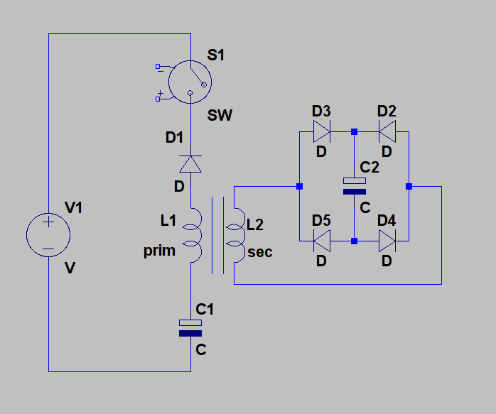
If that is the key mechanism, basically using a changing electric field to create a magnetic field inside a coil while delaying the moment a current can flow, because of the use of a device containing an electrolyte, then there may be a way to close the loop after all. This would be something like this in the way Gray did it:
However, Zooty's extra (green) coil could of course also be the primary of a transformer, while the secondary could be used to charge the source battery without directly closing the loop.
I came to this idea, because according to Mark McKay, the batteries were essential in Gray's stuff, and there are also a few strange (electrolytic!) capacitors in Bedini's schematic of the so-called Tesla switch:
Mark McKay posted some information on the earlier, succesfull, Gray engines which I think is very important also for understanding the Tesla switch:
Spokane1 wrote:
There is meaningful observation documented where the non-classical output was a simple, but huge, DC spike that recharged the storage capacitor(s) and was also directed towards the storage batteries. The batteries were destroyed by this input -BUT they could not be eleminated from the circuit. Their circuit parameters were a requirment for non-classical operation. The motor could never run "closed loop" becasue the energy that was not extracted in the form of torque couldn't be effectively stored. They only needed a 60A alternator to top off the batteries from a functional standpoint. But if the motor ran for more than 30-60 minutes the batteries were toasted. If the motor was ran longer than this they exploded from hydrogen outgassing. Today this challenge might be solved with some huge carbon foam capacitors and sophiscated switch-mode power supply circuits.
So, according to Mark,
the batteries are essential for "non-classic operation" and that this is a
documented observation. To me, this is one of the most important clues I have read ever since I started studying Grays stuff. And since this comes from McKay, one of the most knowledgeable persons on the history of Grays stuff, I have no doubt this is accurate. And beside that, John Bedini has also stated the importance of batteries in his systems. "
It's in the batteries!", is what I recall hearing him say on one of his video's.
Just like I wondered what capacitor 38 in Grays circuit is for, I also wondered why there are capacitors in the lines to the diode bridge in the most original working Tesla switch schematic I know of, the one on page 8 here:
As you can see, this one powers an inductive load, a motor, while being fed trough electrolytic capacitors in the line to the rectifier bridge.
It appears that devices containing metal plates with a water solution in between them, be it a battery, an electrolytic capacitor or a WFC, in combination with an inductor are essential for obtaining excess energy.
As I posted here, according to the Maxwell equations, a magnetic field can not only be caused by a current, but also by a changing electric field:
Maxwell's equations - Wikipedia, the free encyclopedia
by changing electric fields
This suggests it is very likelly possible to create a magnetic field inside a coil using only a changing electric field, without having to provide any current to the coil in order to get the magnetic field.
Interestingly, Bedini uses the same principle the other way around. He energizes a coil trough a transistor and then suddenly switches the transistor off, so no current can flow trough the transistor anymore. He redirects the sharp rising voltage at the coil terminal trough a diode to a charging battery. And then you get a DC spike, exactly
because the ion based current inside the battery takes some time to react.
So, it appears that with electrolytic capacitors, you get a short delay between the moment a field, a voltage, is applied to it and the moment a current starts flowing. And it appears this effect can be used to cause a magnetic field to build up inside a coil, without providing current to it, while the energy that has been build up in the coil can be harnassed for free.
Given that Gray's system includes a capacitor 38 and his schematic supposedly originate with Tesla, and Marvin Cole could not get this system to work without batteries, one can speculate that the plate distance of the electrolytic capacitors/batteries used is an important parameter for the effects we are after. And therefore it seems likely that old school electrolytic capacitors, basically aluminum plates in an electrolyte solution, offer the best results.
For more on how to make old school electrolytic capacitors as well as rectifiers, see:
http://www.energeticforum.com/renewa...tml#post123445





 The modification of the electric flyswatter
 You can semplify a lot using only one IC OSCILLATOR/HALF-BRIDGE DRIVER like IR2153 and IRFP450 mosfets.. in fact Puharich use ONLY alternate voltage and right cell (not metal only). Ask to you why Puharich use dieletric inside injector. Your cell is an antenna and you can tuned simply
