report
Water as fuel
1 January 1995
Page 113
Moat Cottage
The Dnve
Bosham
West Sussex PO18 8JG
WATER AS FUEL
Dear Stan,
HAPPY INDEPENDENCE DAY !
] enclose a copy of my Southampton paper which has to be in the hands of the Institute during the coming week for printing and improvement, | hope, in the quality of some of the figures, especially the photographs.
This version, (the sixth draft) is technicaly the same as the one which I sent to you on the 17th May, except that I have substituted a different, and hopefully more correct, treatment of the Second Law of Thermodynamics. I have also included a reference to the welcome paper you sent me by Gary Jonson of Kansas State University
The subsequent pages have been substantially altered mainly by deleting the whole section on United Nations Relief Ships and reducing the treatment of cargo submarines in order to increase the balance of the Paper in favour of WFC.
1 am relieved to say that Dr Harold Aspden, a physicist attached to Southampton University who tells me he introduced you when you spoke at Denver Colorado, had no adverse comments or corrections to make. I hope you are happy too.
Meanwhile I am very glad to report that David Goodrich, the managing director and Chief Executive of British Maritime Technology, (the leading centre of excellence on naval architecture in the UK) has pledged his full support for WFC. I hope to get a similar commitment from Stone Vickers (the main pump-jet company in the UK) when I meet them on 7th July. Unfortunately I have been unable to see Rolls Royce, the marine gas-turbine people at Ansty, but they have orally registered a distinct interest. ] shall have more to report when we meet on 18th July.
Mark Cliff sends his apologies about the necessary change to his plans. He will now arnive a day late, ie. on Monday 19th July, and make his own way by hire-car direct to the Red Roof Inn. I would be grateful if you could let the hotel know that he will need his room for one night instead of two and if Charlie Holdsworth's demo could be run on the morning of Tuesday 20th July. We need to convince Mark that it is ‘over unity.’
I hope this means that on Monday 19th July you and I can concentrate on the subject of your plans for demonstrations in Ohio and London, and also how best to promote hyperdrive, marine gas-turbines, and heavy slow speed marine diesels. | assume that all is proceeding smoothly with Perkins.
Am very relieved to hear that you managed to steer the tornado out of harm's way. It must have been a thoroughly alarming experience.
With my warmest regards
Page 114
WATER AS FUEL
Admiral Sir Anthony Griffin
ABSTRACT
The Earth's main sources of non solar energy are fossil] fuels, which Cause severe Pollution and-_cannot last indefinitely; nuclear, which is capital intensive, and whose waste disposal is problematical: tidal and wind schemes which are inefficient; and thermal and hydro installations which are efficient but lack flexibility and require major capital investment.
An alternative is water (salt, fresh or distilled) as a cheap and inexhaustible source of global energy which has none of the foregoing disadvantages. The theoretica] evidence in support of the relevant technology is briefly described and related to the first and second laws of thermodynamics. Practical evidence is illustrated and the impact of this revolutionary development on the marine industries, with ships floating on their own fuel and thus having no need for either bunkers or ambient
Much wider and global implications for the environment, industry, defence and Political Stability are discussed.
AUTHOR'S BIOGRAPHY
from RN in 1975 to become first Chairman of British Shipbuilders from 1975 -80; President of the Royal Institution of Naval Architects 1981 - 84, and founder member of the British Maritime League and the British Maritime Charitable
~~ - ipa naa me__fl
a aut
Page 115
WATER AS FUEL
INTRODUCTION
In 1972 the Royal Navy examined how the Fleet should be fuelled when current fossil fuels became too scarce, say in the year 2030. They concluded that the fuel of the future was hydrogen but that, as this gas was not normally available in usable form. it would havc to be extracted through either the electrolysis of water or nuclear fusion. Neither appeared to be immediately practicable. Electrolysis needed more power than that of the hydrogen it yielded and was too Slow a process to meet the demands of an internal combustion engine. This meant that it would have to be stored in either liquid form or in a fuel cell, both of which involved substantial weight or safety problems. Nuclear fusion appeared to be too distant and expensive
an alternative.
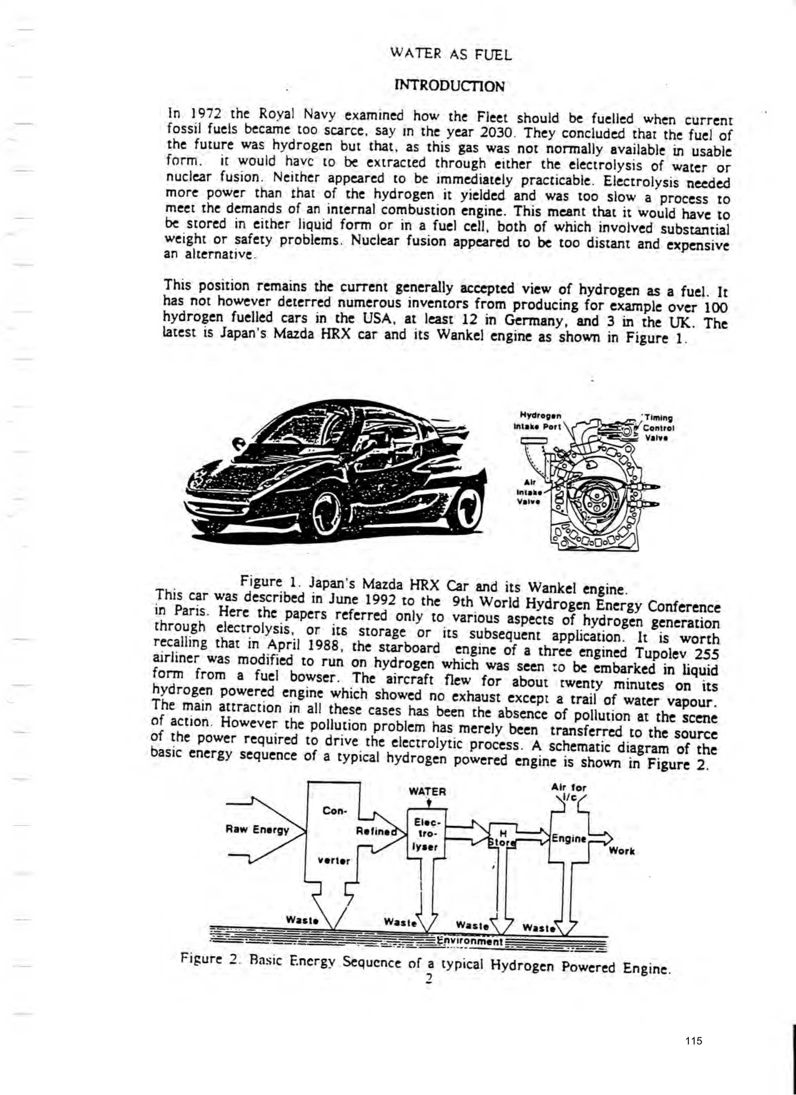
This position remains the current generally accepted view of hydrogen as a fuel. It has not however deterred numerous inventors from producing for example over 100 hydrogen fuelled cars in the USA, at least 12 in Germany, and 3 in the UK. The latest is Japan's Mazda HRX car and its Wankel engine as shown in Figure 1.
Hydrogen intake Port
= Valve
Sat:
Figure 1. Japan's Mazda HRX Car and its Wankel engine.
This car was described in June 1992 to the 9th World Hydrogen Energy Conference in Paris. Here the papers referred only to various aspects of hydrogen generation through electrolysis, or its Storage or its subsequent application. It is worth recalling that in April 1988, the Starboard engine of a three engined Tupolev 255 airliner was modified to run on hydrogen which was seen to be embarked in liquid form from a fuel bowser. The aircraft flew for about twenty minutes on its hydrogen powered engine which showed no exhaust except a trail of water vapour. The main attraction in all these cases has been the absence of pollution at the scene of action. However the pollution problem has merely been transferred to the source of the power required to drive the electrolytic process. A schematic diagram of the basic energy sequence of a typical hydrogen powered engine is shown in Figure 2.
Raw Energy
Environment ———_—
Basic Energy Sequence of a typical Hydrogen Powered Engine.
Figure 2.
Page 116
WATER AS FUFI.
DR.CORNISH'S HYDROGEN SUPPLY UNIT
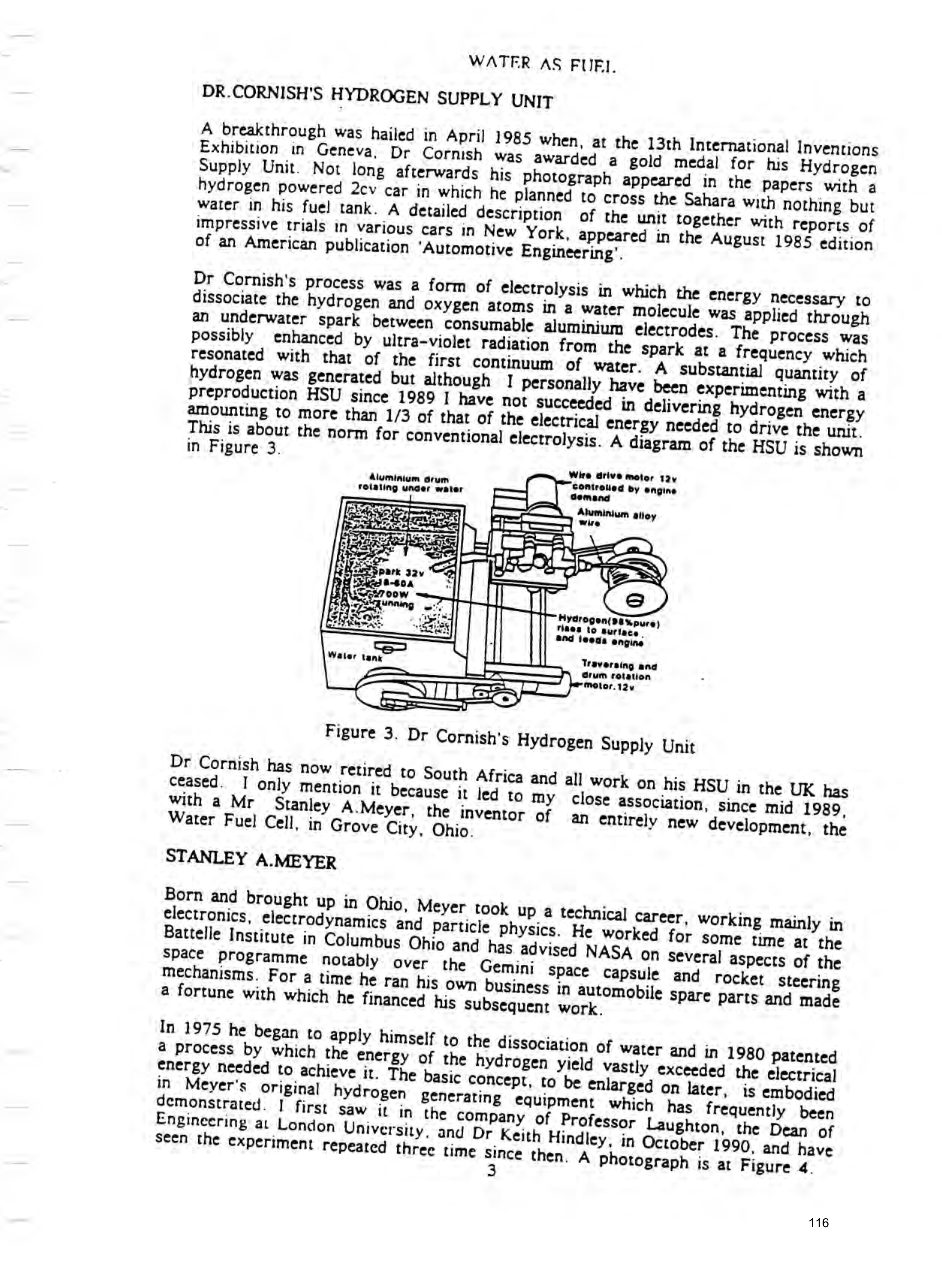
A breakthrough was hailed in April 1985 when, at the 13th International Inventions Exhibition in Geneva, Dr Cornish was awarded a gold medal for his Hydrogen Supply Unit. Not long afterwards his photograph appeared in the papers with a
hydrogen was generated but although | personally have been experimenting with a
Wire drive motor Ta
Aluminium drum controlled by engine rotating uncer water Gemand
Aluminium alloy wie
riaes to Burlace | and feeds engine
Water wa | Traversing and
Grum rotation
Figure 3. Dr Cornish's Hydrogen Supply Unit
Dr Cornish has now retired to South Africa and all work on his HSU in the UK has ceased. I only mention it because it led to my close association, since mid 1989, with a Mr Stanley A.Meyer, the inventor of an entirely new development, the Water Fuel Cell, in Grove City, Ohio.
STANLEY A.MEYER
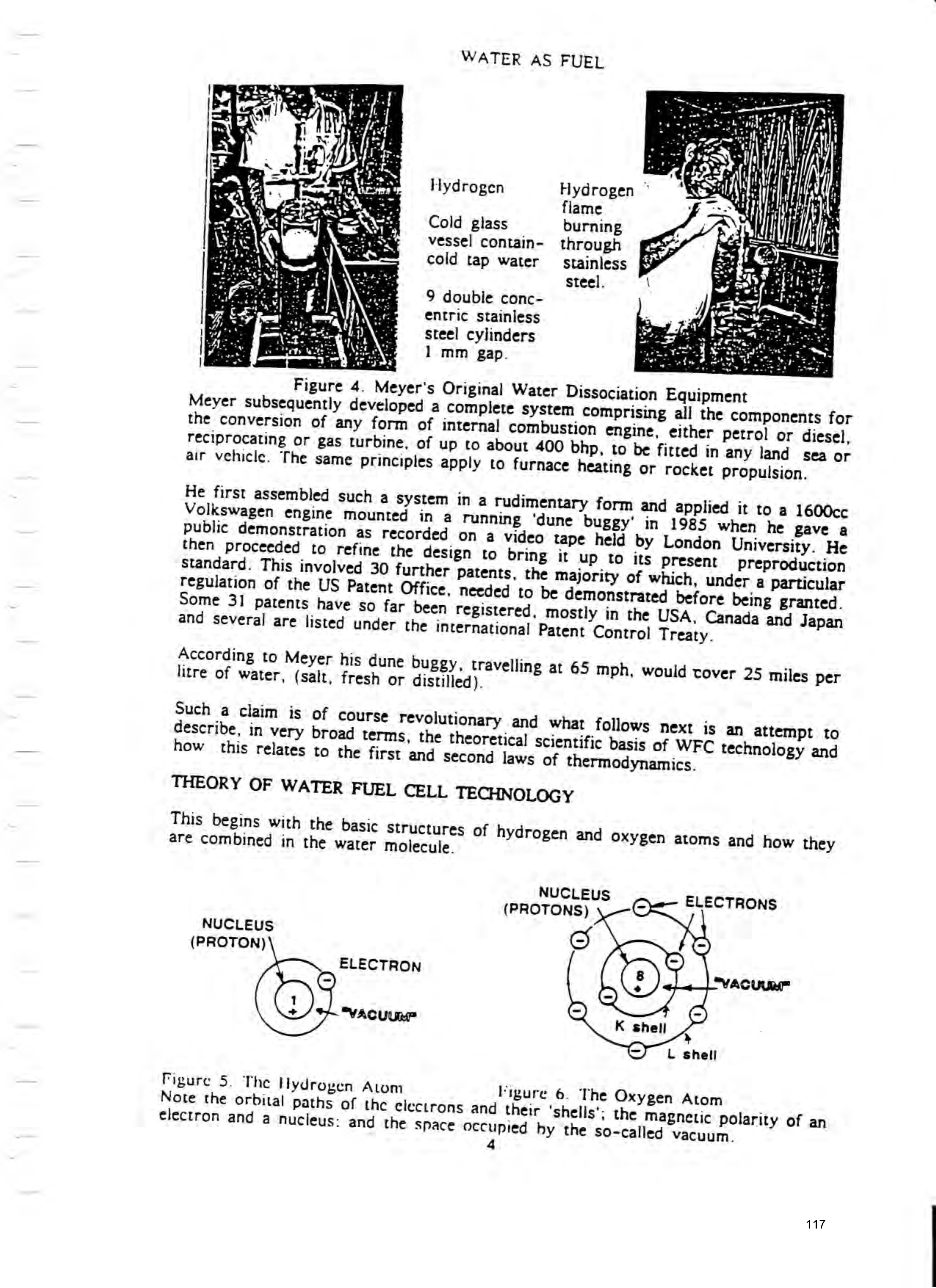
In 1975 he began to apply himself to the dissociation of water and in 1980 patented a process by which the energy of the hydrogen yield vastly exceeded the electrical energy needed to achieve it. The basic concept, to be enlarged on later, is embodied in Meyer's original hydrogen generating equipment which has frequently been demonstrated. | first saw it in the company of Professor Laughton, the Dean of Engineering at London University, and Dr Keith Hindley, in October 1990, and have seen the experiment repeated three time since then. A Photograph is at Figure 4.
Page 117
WATER AS FUEL
Hydrogen Hydrogen © flame
Cold glass burning vessel contain- through cold tap water stainless steel.
9 double concentric stainless steel cylinders ae 5 1 mm gap.
pea
Figure 4. Meyer's Original Water Dissociation Equipment
Meyer subsequently developed a complete system comprising all the components for the conversion of any form of internal combustion engine, either petrol or diesel, reciprocating or gas turbine, of up to about 400 bhp, to be fitted in any land sea or air vehicle. The same principles apply to furnace heating or rocker propulsion.
He first assembled such a System in a rudimentary form and applied it to a 1600cc
Volkswagen engine mounted in a running ‘dune buggy’ in 1985 when he gave a public demonstration as recorded on a video tape held by London University. He
According to Meyer his dune buggy, travelling at 65 mph, would tover 25 miles per litre of water, (salt, fresh or distilled).
THEORY OF WATER FUEL CELL TECHNOLOGY
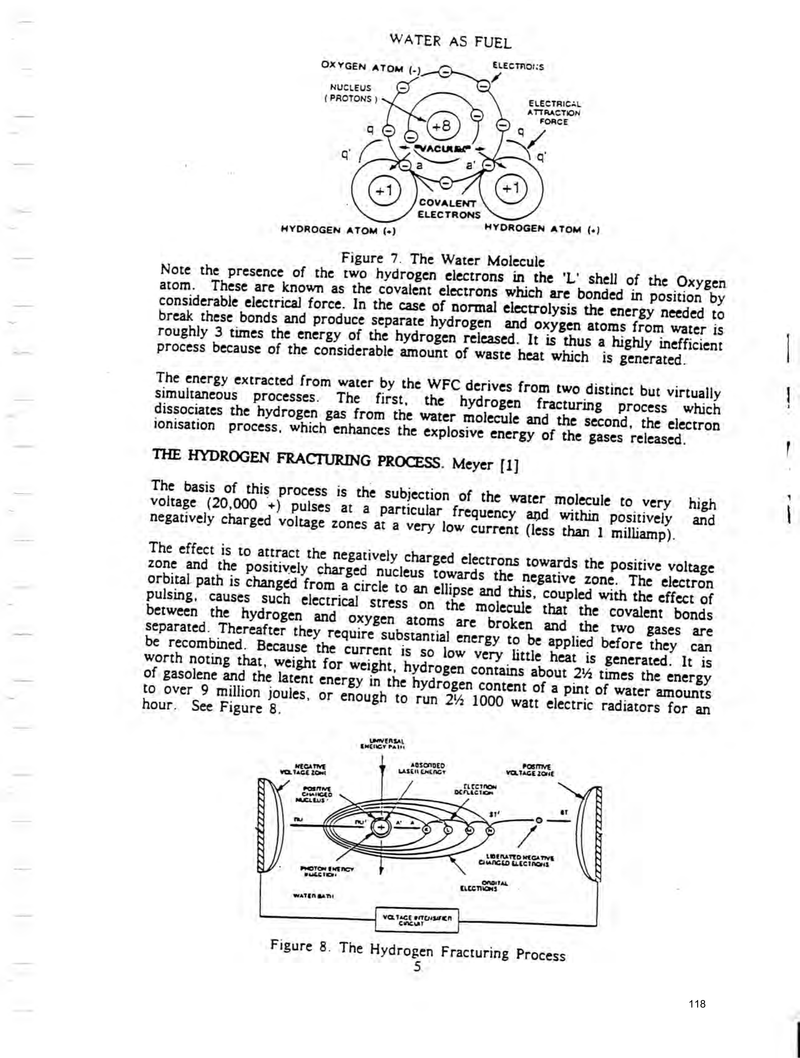
This begins with the basic structures of hydrogen and Oxygen atoms and how they are combined in the water molecule.
NUCLEUS
(PROTONS)
ELECTRONS
NUCLEUS
(PROTON)
ELECTRON "VACUUM
L shell
Figure 5. The Hydrogen Atom Migure 6. The Oxygen Atom
Note the orbital paths of the electrons and their ‘shells’; the magnetic polarity of an electron and a nucleus: and the space occupied by the so-called vacuum.
Page 118
WATER AS FUEL
ELECTRONS
OXYGEN aTom (-)
NUCLEUS avis.
TONS ELECTRICA)
SPACTONS } ATTRACTION
FORCE
ELECTRONS
HYDROGEN ATOM (.)
HYDROGEN ATOM (-)
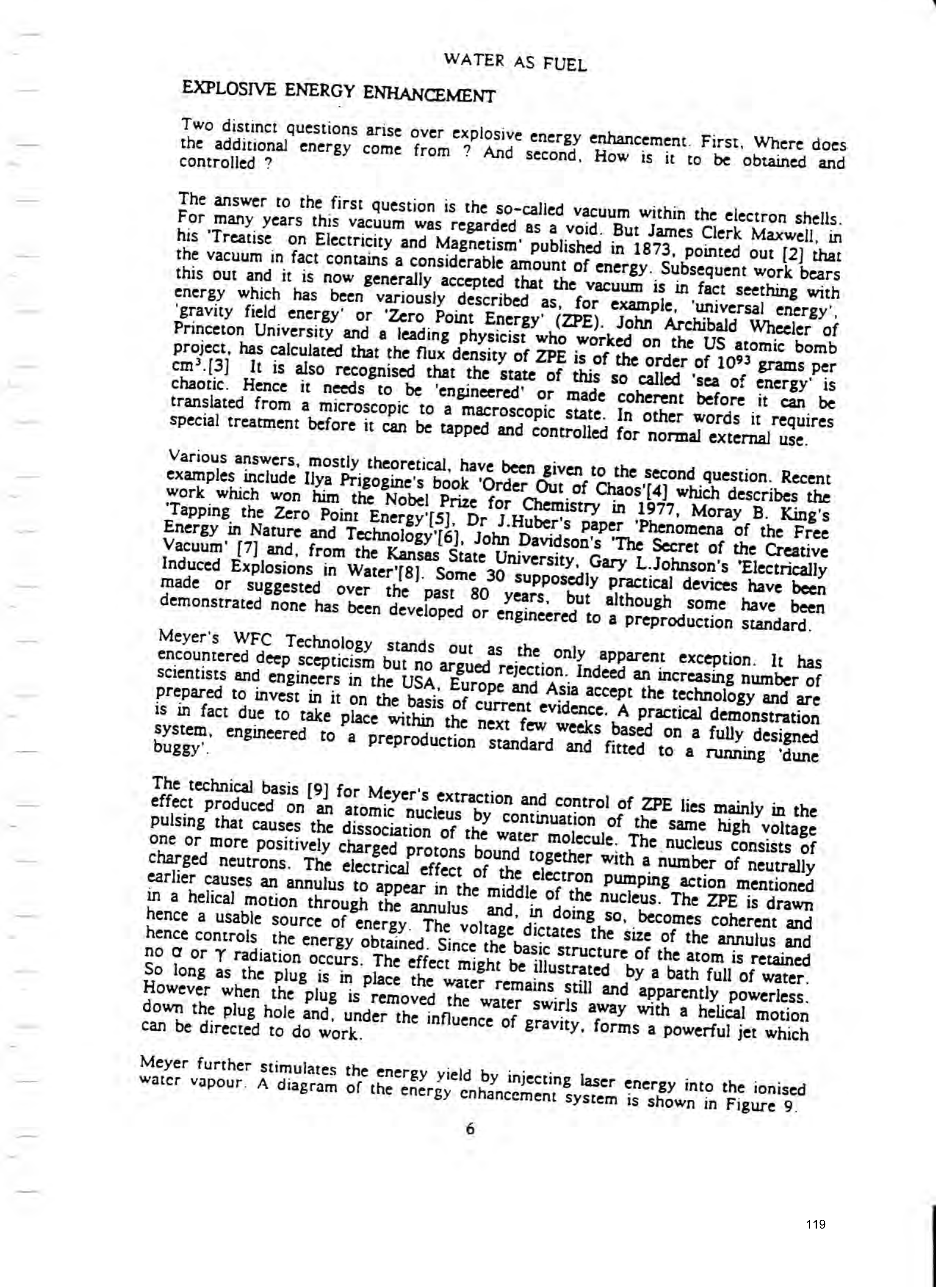
Figure 7. The Water Molecule
Note the presence of the two hydrogen electrons in the 'L' shell of the Oxygen atom. These are known as the covalent electrons which are bonded in position by considerable electrical force. In the case of normal electrolysis the energy needed to
The energy extracted from water by the WFC derives from two distinct but virtually Simultaneous processes. The first, the hydrogen fracturing process which dissociates the hydrogen gas from the water molecule and the second, the electron ionisation process, which enhances the explosive energy of the gases released.
THE HYDROGEN FRACTURING PROCESS. Meyer [1]
The basis of this process is the subjection of the water molecule to very high voltage (20,000 +) Pulses at a particular frequency and within Positively and negatively charged voltage zones at a very low current (less than 1 milliamp).
S¢parated. Thereafter they require substantial energy to be applied before they can be recombined. Because the current is so low very little heat is generated. It is worth noting thar, weight for weight, hydrogen contains about 2% times the energy of gasolene and the latent energy in the hydrogen content of a pint of water amounts to over 9 million joules, or enough to run 2% 1000 watt electric radiators for an hour. See Figure 8,
UMVERSAL
EMCHGY Pain ansonnEeo POSITIVE wo MEGANE Y uasen cvener VOLTAGE Zone
TLECTAOs rte DCLEcticn
Crmnceo
LWEMATEO wEGA TIVE
CUNGED LECTROHS
PROTON Ewency
PUSEVES! OngiTAL
CLccTicNs
wWaTEN gan:
VOLTACE erTcusareen cme
Figure 8. The Hydrogen Fracturing Process
Page 119
WATER AS FUEL
EXPLOSIVE ENERGY ENHANCEMENT
Two distinct questions arise over explosive energy enhancement. First, Where does the additional energy come from ? And second, How is it to be obtained and
controlled ?
The answer to the first question is the so-called vacuum within the electron shells. For many years this vacuum was regarded as a void. But James Clerk Maxwell, in his ‘Treatise on Electricity and Magnetism’ published in 1873, pointed out [2] thar
Project, has calculated that the flux density of ZPE is Of the order of 1093 grams per cm?.[3] It is also recognised that the state of this so called ‘sea of energy’ is
Energy in Nature and Technology'[6], John Davidson's ‘The Secret of the Creative Vacuum' [7] and, from the Kansas State University, Gary L.Johnson’s Electrically Induced Explosions in Water'[8]. Some 30 Supposedly practical devices have been made or suggested over the past 80 years. but although some have been demonstrated none has been developed or engineered to a Preproduction standard.
The technical basis [9] for Meyer's extraction and control of ZPE lies mainly in the effect Produced on an atomic nucleus by continuation of the same high voltage pulsing that causes the dissociation of the water molecule. The nucleus consists of
Page 120
WATER AS FUEL
Ear re errsrs:
TIT G Creeps rrr ery
Lo epee ees acre
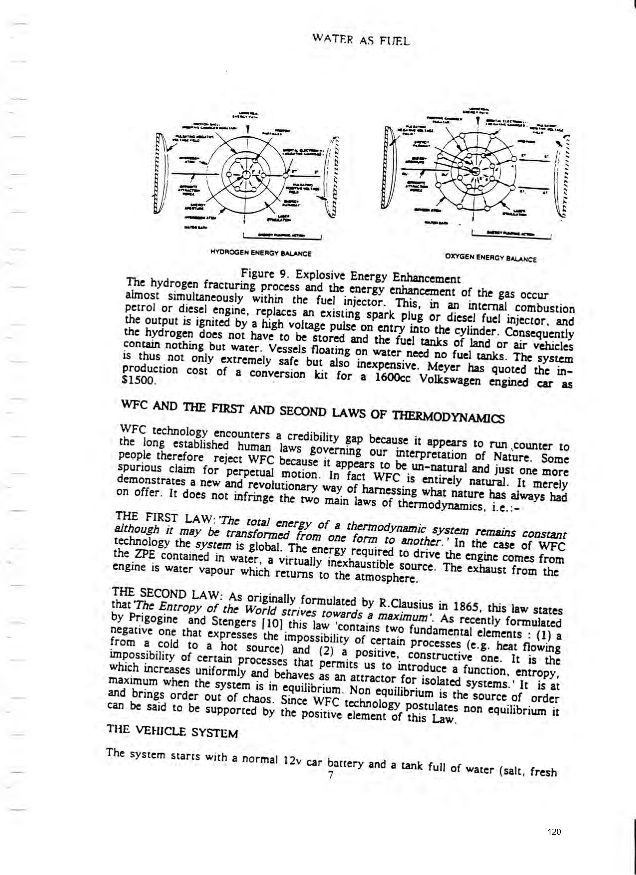
HYDROGEN ENERGY BALANCE OXYGEN ENERGY BALANCE
Figure 9. Explosive Energy Enhancement
The hydrogen fracturing process and the energy enhancement of the gas occur almost Simultaneously within the fuel injector. This, in an internal combustion petrol or diesel engine, replaces an existing spark Plug or diesel fuel injector, and the output is ignited by a high voltage pulse on entry into the cylinder. Consequently
WFC AND THE FIRST AND SECOND LAWS OF THERMODYNAMICS
WFC technology encounters a credibility Bap because it appears to Tun counter to the long established human laws governing our interpretation of Nature. Some
THE SECOND LAW: As originally formulated by R.Clausius in 1865, this law states that ‘The Entropy of the World Strives towards a maximum’. As recently formulated by Prigogine and Stengers [| 10] this law ‘contains two fundamental elements :(l)a negative one that expresses the impossibility of certain Processes (e.g. heat flowing Tom a cold to
which increases uniformly and behaves as an attractor for isolated Systems.' It is at
THE VEHICLE SYSTEM
The system starts with a normal 12v car battery and a tank full of water (salt, fresh
Page 121
WATER AS FUEL
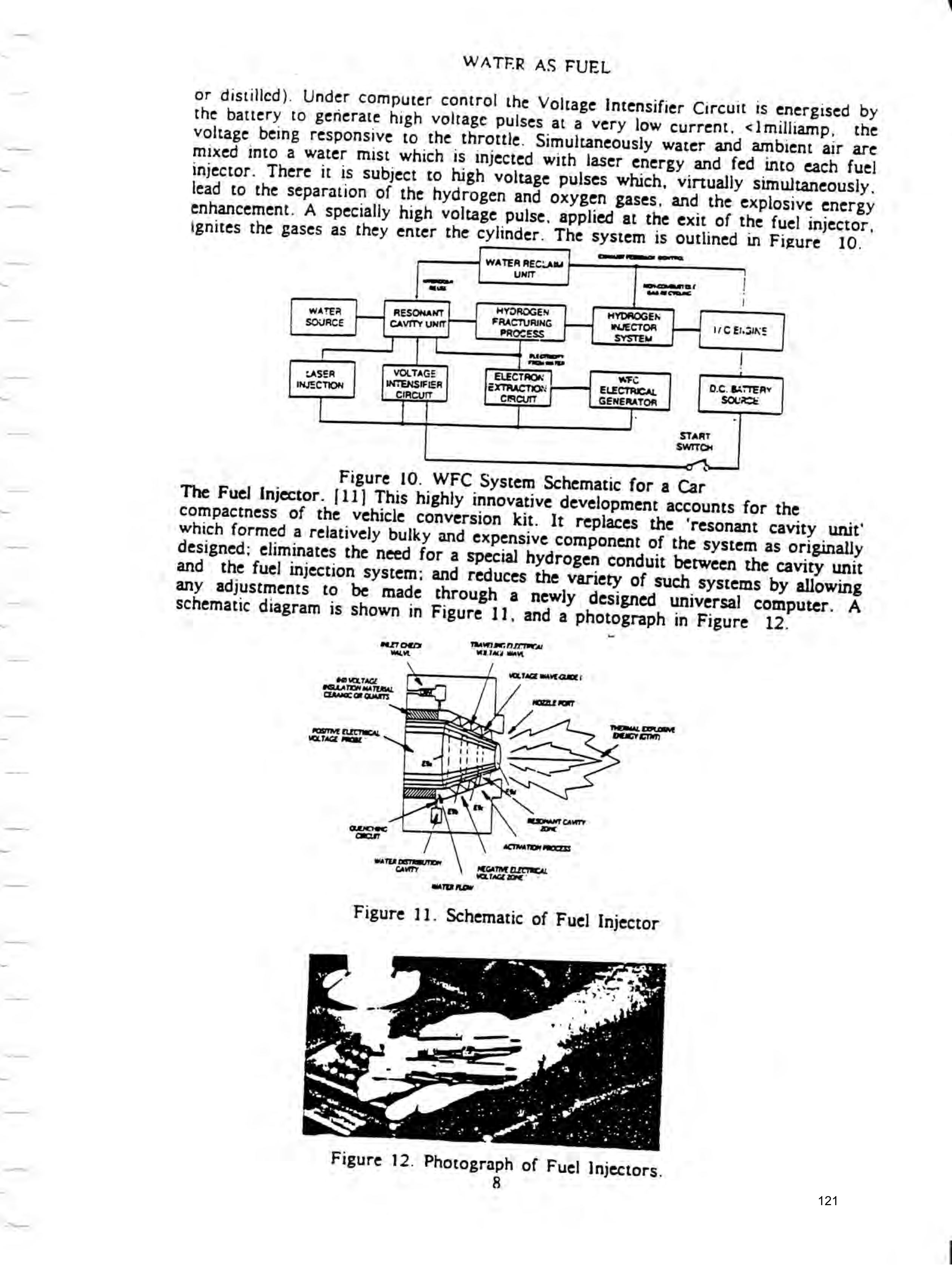
the battery to generate high voltage pulses at a very low current, <1 milliamp, the voltage being responsive to the throttle. Simultaneously water and ambient air are
lead to the separation of the hydrogen and oxygen Bases, and the explosive energy enhancement. A specially high voltage pulse, applied at the exit of the fuel injector, ignites the gases as they enter the cylinder. The system is Outlined in Figure 10.
ow ees eorren,
| WATER RECL aw —
RAF meneuarmi |
HYOROGEN HYDAOGEN
WATEA RESONANT
‘ FRACTURING WJECTOR WCELSINE
SOURCE CAVITY UNIT part ree
if Fe ws FER 3
LASER VOLTAGE ELECTROK WFc DS BATTERY
TION INTENSIFIER EXTRACTION ELECTRICAL G. BATTE:
seme! CIRCuTT emcur GENERATOR Source [i START
SWITCH
Figure 10. WFC System Schematic for a Car
The Fuel Injector. [11] This highly innovative development accounts for the
any adjustments to be made through a newly designed universal computer. A schematic diagram is shown in Figure 11, and a photograph in Figure 12.
TRAVELING ecto
Ee MTA Way \ / OL Tact WAVE Comte
CEAasr GF QUARTS AOZTLE PORT fe Tema CLE
POSTIVE ELECTINcAL
VOLTAGE Pre
Sy bain
RESORANT CAVITY
qnowc ae
ACTIVATION PROCTXS
ATER DosTeRUTIOW
NEGATIVE ELEC Tea cad Vex Tae ore’ ero how
Figure 11. Schematic of Fuel Injector
Figure 12. Photograph of Fuel Injectors.
Page 122
WATER AS FUEL
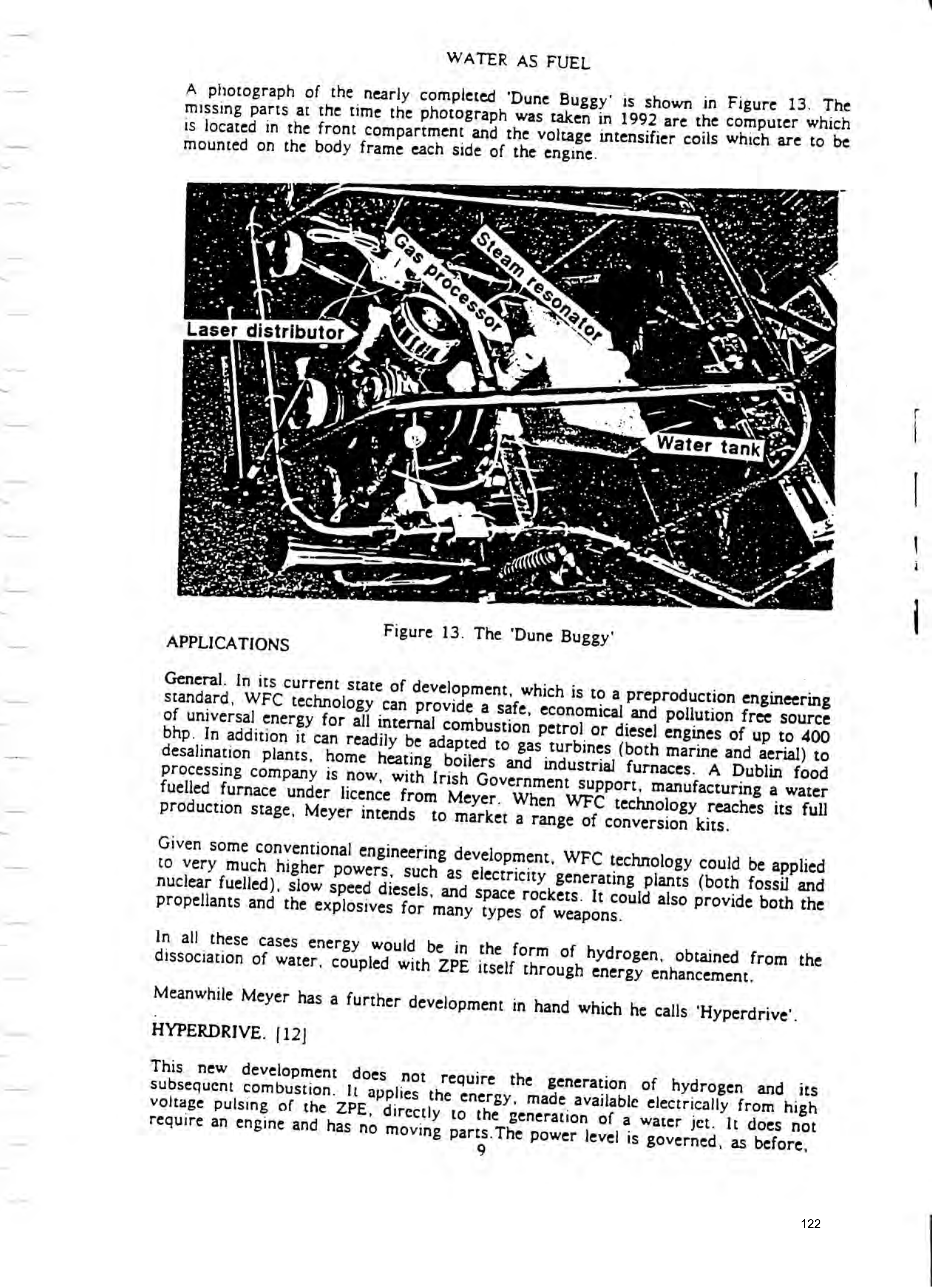
A photograph of the nearly completed ‘Dune Buggy’ is shown in Figure 13. The missing parts at the time the photograph was taken in 1992 are the computer which 1S located in the front compartment and the voltage intensifier coils which are to be mounted on the body frame each side of the engine.
Laser distributor %
Given some conventional engineering development, WFC technology could be applied tO very much higher powers, such as electricity generating plants (both fossil and nuclear fuelled), slow Speed diesels, and space rockets. It could also provide both the propellants and the explosives for many types of weapons.
In all these cases energy would be in the form of hydrogen, obtained from the dissociation of water, coupled with ZPE itself through energy enhancement,
Meanwhile Meyer has a further development in hand which he calls 'Hyperdrive’.
HYPERDRIVE. /12]
This new development does not require the generation of hydrogen and its
subsequent combustion. It applies the energy, made available electrically from high
voltage pulsing of the ZPE, directly to the Beneration of a water jet. It does not
require an engine and has nO moving parts.The power level is governed, as before,
Page 123
WATER AS FUEL
by the applied voltage. Direction is controlled by feeding the jet through manoeuvring nozzles such as those fitted to Harrier v/stol aircraft or space rockets. It is thus of special significance to marine transport.
APPLICATION OF WFC TO MARINE TRANSPORT
Existing Vessels. With the application of a straightforward and inexpensive conversion kit, the present engines of these vessels could be modified to run on hydrogen extracted from the water on which they float. All auxiliary machinery, powered lifeboats etc could be similarly fuelled. The use to be made of redundant fuel tanks, pumps and heaters etc would be a matter of choice.
Vessels Designed for Water Fuel. As these would be designed from the outset to run heir existing machinery on hydrogen, any space or deadweight which would Previously have been devoted to fuel ete could usefully be reallocated by design. Performance, especially speed, need not have to take account of endurance.
Vessels Designed for Hyperdrive. These would be subject to radically new design to accommodate the Hyperdrive power units, including the electrical plant, and
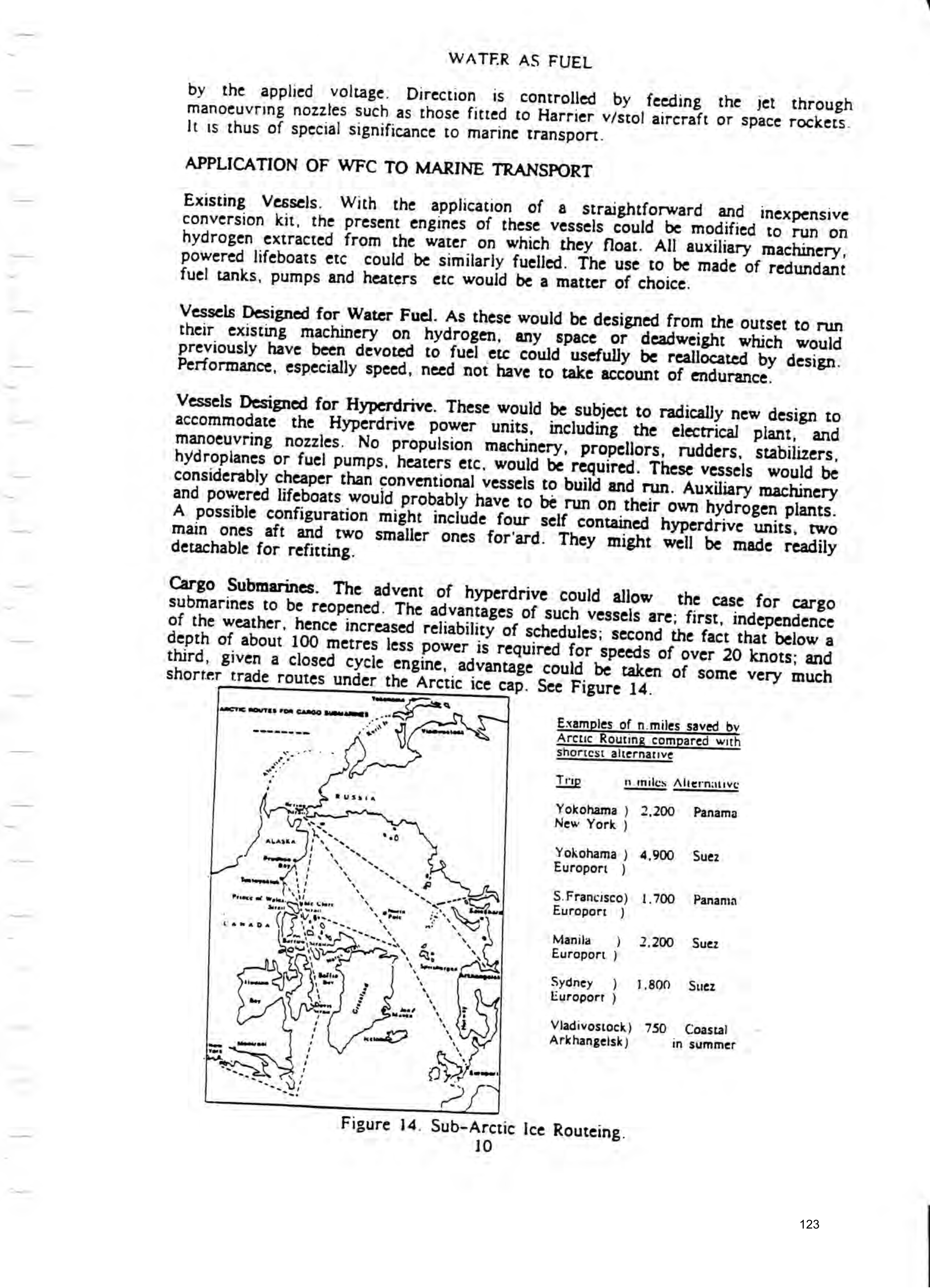
shorter trade routes under the Arctic ice cap. See Figure 14.
ro unto amas we
eee ee
~~ Examples of n.miles saved by
Arctic Routing compared with shortest alternative
Trip nomiles Alternative
Yokohama ) 2,200 Panama
New York )
Yokohama ) 4,900 Suez
Europort )
S.Francisco) 1.700 Panama
Europorr )
Manila ) 2,200 Suez
Europort )
Sydney ) 1,800 Suez
Europort )
Viadivostock) 750 Coastal
Arkhangelsk ) in summer
Figure 14. Sub-Arctic Ice Routeing.
Page 124
WATER AS FURL
Seasonal ice coupled with the shallowness of the water restrict submarine passage through the Bering Strait to August and September. However. given commercial demand it is possible that this restriction could be eased.
Other trading opportunities lie amongst the considerable mineral deposits In the Queen Elizabeth Islands off northern Canada from where under ice submarine passage eastwards would not be affected by conditions in the Bering Strait.
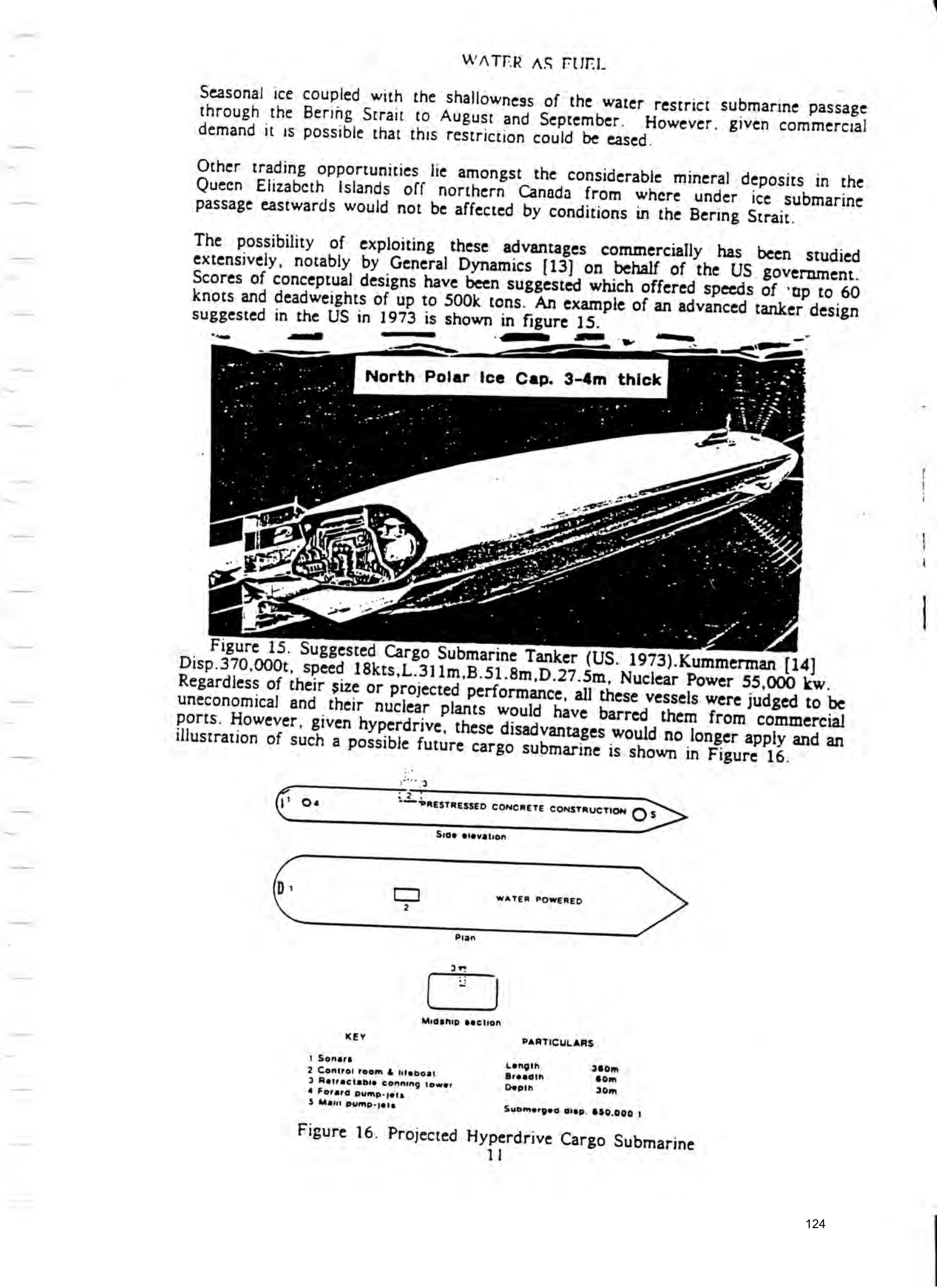
The possibility of exploiting these advantages commercially has been Studied extensively, notably by General Dynamics [13] on behalf of the US government. Scores of conceptual designs have been suggested which offered speeds of ‘ap to 60 knots and deadweights of up to 500k tens. An example of an advanced tanker design
suggested in the US in 1973 is shown in figure 15. ss :
Swat
Figure 15. Suggested Cargo Submarine Tanker (US. 1973).Kummerman [14] Disp.370,000t, speed 18kts,L.311m,B.51.8m,D.27.5m, Nuclear Power 55,000 kw.
ports. However, given hyperdrive, these disadvantages would no longer apply and an illustration of such a Possible future cargo submarine is shown in Figure 16.
fey
}' Oa “= PRESTRESSED CONCRETE CONSTRUCTION oO 5
Side sievation
D: C4 WATER POWERED
Midsnip section
KEY PARTICULARS
1 Sonars Length 360m 2 Control room & iiteboat Breacin som 3 Retractabie conning tower Depin 30m 4 Forara Pump-jets
S Main Pump-jeis Submerged gisp, 650.000 ;
Figure 16. Projected Hyperdrive Cargo Submarine
Page 125
WATER AS FUEL
Water Refuelling of Aircraft. Aircraft which can fly low over water, notably helicopters, but also including certain fixed wing aircraft, could readily be adapted to include water scoops in the Same way as French Riviera fire-fighting aircaft are now fitted for replenishing their water tanks. The endurance of aircraft so fitted would not be restricted by the Capacity of their water fuel tanks.
THE POTENTIAL BENEFITS OF WFC TECHNOLOGY
Elimination of Fossil Fuel Pollution. This would apply both locally and globally. In urban areas, such as Los Angeles, Athens, Tokyo and many other cities, Pollution is an increasingly serious and apparently insoluble problem. Similarly prevailing weather patterns are said to spread pollution internationally and at the Rio de Janeiro conference concern was expressed about harmful damage being done to the World ecosystem. Meanwhile vast resources are being expended on partial palliatives such as desulphurisation plants for power Stations and the elimination of CFCs.
and on land, not forgetting massive problems over the disposal of nuclear waste
Cost Savings in Energy Production. Huge financial Savings could be made over the research, production and distribution of almost all current forms of energy. (Hydroelectric and gco-thermal plants excepted).
Cost Savings in Energy Consumption. According to 'The Economist's 'Viral World Statistics’ the World's total energy consumption in 1987 amounted to about 9.6 was of coal equivalent. In 1990 the Marine industry, according to the OECD,
Reaction of Current Energy Interests to Threat of Displacement. Vast resources have been committed in people and money to develop, promote and maintain whole energy industries in the fields of coal, gas, oil, and nuciear power. These investments cannot sensibly be closed down Precipitately without Causing major disruption and unrest. In several areas, such as the Middle East, Central America and Indonesia, national economies have become heavily dependent On national sources of fossil fuel. Consequently whole arcas of the world could well become
Page 126
WATER AS FUEL
politically destabilised. Such a prospect, together with the natural concern: of energy producers, could well threaten the introduction of WFC technology, as has frequently been foreshadowed during recent years by death threats and several proffered multi-million dollar inducements.
Desalination. Massive desalination of sea water could give Tise to an excessive concentration locally of brine. Remedies need to be identified and applied.
COUNTER ARGUMENTS TO THREATS AGAINST WFC
The following arguments could usefully be deployed :-
a. The World's energy demands are increasing especially because the World's population, now about 10 billion, is forecast to double during the next century. Existing sources of energy should therefore be maintained so far as
solutions to the pollution and nuclear problems allow.
b. Fossil fuels are likely to be exhausted within the next century. c. The pollution problem needs urgent solutions.
d. There is a serious and increasing risk of major accidents amongst many nuclear power stations.
e. It may well take several decades before the application of WFC technology becomes significant.
f. There are more constructive uses, such as fertilizers and plastics, for fossil products than just burning them. It is possible that new fossil products could attract higher prices than are now obtainable for fuel.
g. WFC offers major global benefits, not least for the Developing World where competition for scarce resources causes civil war and Starvation. The need is urgent. Plentiful free erergy should provide such widespread economic benefits as substantially to reduce future threats to World peace.
h. With the exception of the urgent action needed to deal with pollution and dangerous nuclear power plants, there should be enough time to make reasonably orderly adjustments to the World's current energy supply industries.
CONCLUSIONS
General a. WFC Technology offers a real Prospect of a universal, ecologically friendly, economical and inexhaustible source of energy.
b. Its introduction would solve all the pollution problems now caused by fossil and nuclear fuels.
c. WFC technology would greatly benefit the world's economy as a whole. In the developing world, such tensions as civil wars and Starvation, brought about by competition for scarce resources, could be significantly eased.
d. Weapons would be cheaper and hence tend to proliferate. This could result in increased threats to world peace. The UN would have to be prepared to provide adequate safeguards.
Page 127
WATER AS FUEL
¢. Major opposition must be expected to the introduction of WFC ‘technology because of the threat it appears tO pose to powertul vested interests and, in certain areas, political stability. There are powerful arguments for countering such Opposition.
Impact on Marine Industries
&. As vessels would be floating on their own fuel, propulsion and other machinery in existing vessels should be converted to WFC technology as soon as possible. This would save all fuel costs, (except lubricants) amounting to about 30% of total running expenses. In many cases it should be Possible to make further gains by Putting existing bunker spaces and fuel facilities to better use. "
b. Designs for new vessels should be modified as soon as Possible both to include hydrogen fuelled conventional machinery and to design out, to commercial advantage, the need for bunkers and associated pumps, heaters etc.
c. There are major opportunities, especially in the marine field, for collaboration with Meyer over WFC developments for the immediate future. Potential conversion kits range from small outboard motors through, for example, auxiliary machinery and refrigeration plants to slow speed marine diesels and marine gas turbines of many thousands of horsepower.
d. A further substantial R&D programme is required, in close collaboration with Meyer, to bring Hyperdrive into service. Considerable technology is already available amongst existing marine pump jets and the control systems installed in aircraft and Space vehicles.
¢. More radical designs for vessels and submarines of all sizes should now be initiated to incorporate Hyperdrive with its elimination of the need for conventional Propulsion machinery, Propellors, rudders, stabilizers and hydroplanes.
f. Consideration Should be given to the introduction of cargo submarines, powered by Hyperdrive. and constructed out of a new form of concrete material.

Page 128
WATER AS FUEL
REFERENCES
1 Meyer, Stanley A. Hydrogen Fracturing Process. Memo WFC 420. Grove City Ohio. 1990(C)Stanley Meyer.
2. Maxwell,James Clerk. A Treatise on Electricity & Magnetism. 1873 Paperback
3. King, Moray.B. Tapping the Zero-Point Energy. Provo,Utah 1989.(C)King,p158
4. Prigogine. Ilya and Stengers, Isabelle. Order out of Chaos. New York 1984. Chapter IX.
5. King,Moray B. ibid.1989. Electrolytic Fusion: A Zero-Point Energy Coherence?
6. Huber. J. Phenomena of the Free Energy in Nature and Technology. raumé&zeir
7. Davidson, John. The Secret of the Creative Vacuum, chapter 11. C.W.Daniel
8. Johnson. Gary L. Kansas State University, ‘Electrically Induced Explosions in Water’ Johnson's description of his technology has much in common with WFC.
9. Meyer, Stanley A. Atomic Energy Balance of Water. Memo WFC 424. Grove City, Ohio 1991. (©Stanley A.Meyer.
10. Prigogine. Ilya and Stengers, Isabelle. Order out of Chaos. New York 1984. Chapter IV.
11. Meyer, Stanley A. Water Fuel Injector. Memo WFC 425. Grove City, Ohio 1992. Stanley A.Meyer. ze
2. Meyer, Stanley A. Hyperdrive. Memo WFC 455/455DA. Grove City,Ohio 1991. tanley A.Meyer.
13. General Dynamics Corporation. Summary of a Feasibility Study on Submarine
14. Kummerman Foundation. Ships and Shipping of Tomorrow 1983. p.108.
Provenance
- Pages
- pages 113–128 of 140
- Binder
- WFC Project Binder 423-DA
- Method
- pdftoppm 300dpi + tesseract 5 (eng), orientation-corrected
- Source
- WFC International Independent Test-Evaluation Report (1995), scanned binder
- Attribution
- Admiral Sir Anthony Griffin
- Reproduced material
- Reproduced inside Meyer's 1995 report as bound; copyright is the original author's.