patent · US2653481
Temperature-compensated gyroscope
29 September 1953
Page 1
Drawing sheet — no readable text.
Page 2
Patented Sept. 29, 1953
UNITED STATES PATENT OFFICE
GYROSCOPE
James C. Mathiesen, Pleasantville, N.Y., assignor to The Norden Laboratories Corporation, White
Plains, N. Y., a corporation of Connecticut
Application February 19, 1952, Serial No. 272,389
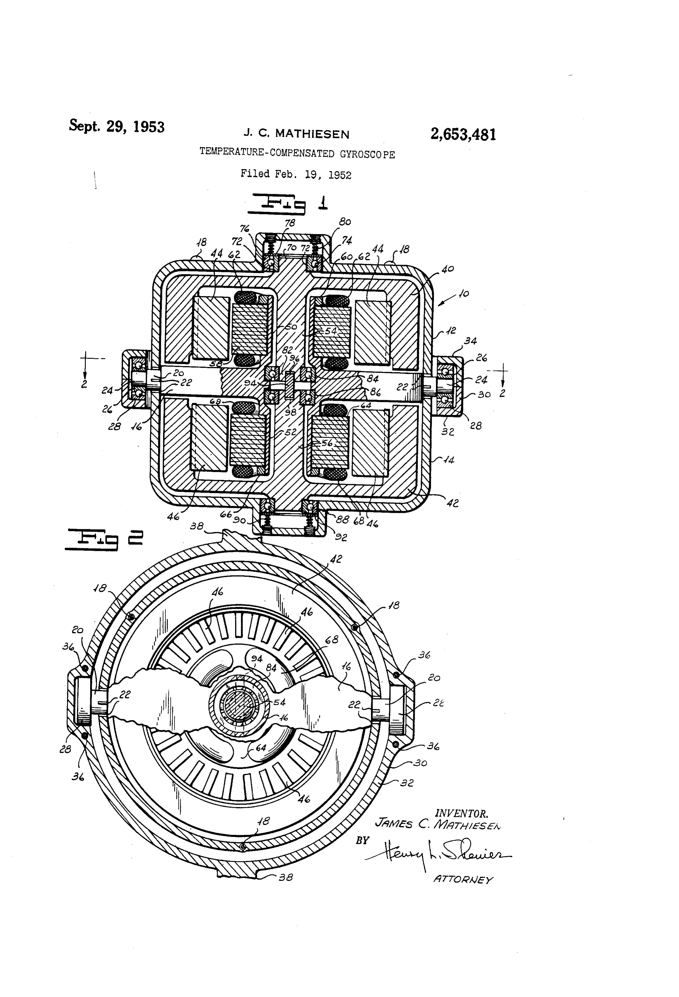
My invention relates to temperature-compen More particularly referring now to the draw Sated gyroscopes and more particularly to a ings, a gyroscope housing indicated generally by gyroscope which will automatically compensate the reference numeral O is formed by two iden itself for unbalancing forces which would nor tical cup-shaped members 2 and 4 and a cen mally be introduced by reason of the expansion tral plate 6. The cup-shaped members are and contraction of metal parts due to tempera adapted to be clamped together by means of ture changes. screws 8. The plate 6 is formed with a pair Gyroscopes are frequently used for many con of trunnions 20 provided with splines 22 adapted trol devices to furnish reference planes. For to coact with the housing members 0 and 4 to these purposes the gyroscope rotor must be care- it provide a rigid framework for supporting the fully balanced to prevent precessional drifts from gyro rotor. For purposes of convenience I Will developing due to unbalance of the rotor with re describe my gyroscope as one in which the Spin Spect to the axes around which the gyroscope is axis is vertical, though it is to be understood that free to pivot. ny invention is applicable to a gyroscope having It has been found that if a gyroscope is bal a spin axis extending along any direction. The anced at One temperature, a change in tempera trunnions 20 are formed with reduced end por ture will frequently result in the production of tions 24 which are carried by the inner races 26 unbalancing forces due to contraction and ex of a pair of ball bearings. The outer races 28 of pansion inherent in the metal of which the rotor the ball bearings are supported by a gimbal ring is made and the manner in which the rotor is 2 3. The gyroscope housing, it will be observed, mounted. Many attempts have been made by is pivoted along a horizontal plane normal to the the art to eliminate this defect. Spin axis. The axis of the trunnions 20 lies along One object of my invention is to provide a the horizontal center line of plate 6. The gin gyroscope which will automatically compensate ball ring 30 is made with a lower part 32 and an itself for the expansion and contraction of the 25 upper symmetrical part 34 adapted to be clamped rotor resulting from temperature changes. together by vertical screws 36, as can readily be Another object of my invention is to provide seen by reference to Figure 2. The gimbal ring a gyroscope structure which when balanced at 32 is in turn formed with a pair of trunnions 38 one temperature will remain in balance through lying in a horizontal plane but extending at right a wide temperature range automatically com angles to the axis around which bearings 26 are pensating for expansion and contraction of metal nositioned. These trunnions are mounted in parts. suitable bearings carried by any desire? support Other and further objects of my invention will (not shown). The gyroscope rotor, therefore, is appear from the following description: thus mounted with three degrees of freedon. The In general, my invention contemplates con gyroscope rotor, per se, comprises an upper sec structing the gyroscope rotor and stator of two tion A9 and a lower section 42, both of which are equal masses and mounting the rotor and stator identical as nearly as they can be made. The symmetrically about, a plane normal to the spin rotor components may be formed of a heavy axis. My construction is such that the expan ineta such as tungsten so that the rotor will have Sion and contraction of the parts will be equal it) a high moment of inetia. The rotor 4 carries and opposite about this plane such that the a plurality of blades 44 forming the sniirrel cage gyroscope will remain always balanced. Advan of an induction motor. The lower rotor 42 car tageously I provide each of the symmetrical rotor ries a plurality of blades 46 likewise forming the elements with floating bearings adapted to ac Squirrel cage of an induction motor. The cen commodate expansion and contraction of the tral plate is is formed with an upper tubular por rotor assembly. tion 50 and a lower tubular portion 52 through In the accompanying drawings, which form which the shaft 54 of the upper rotor and the nart of the instant specification and which are shaft, 56 of the lower rotor respectively, extend. to be read in conjunction therewith and in which arminated core elements 58 are lodged around Jikey reference nurnerals are used to indicate like the upper tube 59 and clamped in position by a parts in the various views: in it, . The stator Winding 62 is disposed about Figure 1 is a sectional elevation of a gyroscope the core laminations 58. Similarly, core lamina assembly containing one embodiment of my in tions 64 are disposed about the lower tube 52 and wention. clamped in position by a nut 66. The winding 68 Figure 2 is a sectional view taken along the 55 for the field of the lower rotor is disposed about line 2-2 of Figure 1, with parts broken away. the core laminations 54. Suitable three-phase
Page 3
alternating current is fed to the windings 62 and is within the scope of my claims. It is further 88, as is well known in the art, to produce a ro obvious that various changes may be made in tating magnetic field which, coacting with the details within the scope of my claims without squirrel cage blades 44 and 46, drives the upper departing from the spirit of my invention. It is and lower rotors. The upper shaft 54 is pro therefore to be understood that my invention is Vided With a reduced end portion 0 carried by not to be limited to the specific details shown the inner race 72 of a ball bearing which is pro and described.
vided with balls 14 and an outer race 76. An Having thus described my invention, what I annular plate 8 contacts the bearing assembly claim is:
and is urged downwardly by a plurality of 0 i. A gyroscope having a housing, a rotor Springs 86. The lower portion of the shaft 54 is mounted in the housing for rotation about a provided with a reduced end portion 82 which is spin axis, means for mounting the housing for carried by a suitable ball bearing 84 in the cen pivotal movement about a tilt axis extending at tral plate 6. The upper portion of lower shaft; right angles to the Spin axis, said rotor being 56 is carried by a ball bearing 86 lodged in the formed with two symmetrical parts of equal mass central plate 6. The bearing seats for bearings each having its own rotor shaft, a bearing Sup 84 and 86 in central plate 6 are symmetrically port member carried by the housing symmetrical disposed, as can readily be seen by reference to with a plane passing through the tilt axis at right Figure 1. The lower portion of lower shaft 56 angles with the Spin axis, a first bearing carried is Supported by a ball bearing 88 similar to the by the support on one side of Said plane, a Second upper ball bearing assembly. The ball bearing bearing carried by the support on the other side 88 is urged upwardly by a plurality of springs 90 of the plane symmetrical to the first bearing, a acting through an annular disk 92. A key 94 has third bearing carried by the housing On. One side its upper portion lodged in a slot 96 formed in the of said plane, a fourth bearing carried by the lower end of shaft 54. The lower end of key 93 2 5 housing on the other side of Said plane Symmetri is lodged in a slot 98 formed in the upper por cal with the third bearing, said bearings being tion of the shaft 56. The key constrains the disposed coaxially with the spin axis, the shaft Upper and lower shafts to rotate together. The of the first rotor part being mounted in the first upper springs 8 constrain the upper bearing to and third bearings, the shaft of the Second rotor move downwardly, thus firmly maintaining the 3.O part being mounted in the Second and fourth shaft against the bearing 84. Similarly, the bearings, means for fixedly positioning one Syn springs 90 bias the ball bearing 88 to constrain metrically carried pair of bearings, means for the shaft 56 to be seated firmly in its upper bear floatingly positioning the other symmetrically ing 86. In this manner the bearings 84 and 86 Carried pair of bearings for movement along the are fixedly positioned in their seats in central 3. 3 spin axis, means for biasing each floating bearing plate 6. As the shafts 54 and 56 expand and toward its companion fixed bearing and meafis contract due to temperature changes, the respec for connecting the rotor shafts to each other for tive outer bearings will move against the action rotation together.
of the respective springs 80 and 90. It will be 2. A gyroscope as in claim 1 in which the fixed observed, however, that this movement is sym 40 bearings are carried by said support member. metrical to the horizontal center line of the cen 3. A gyroscope as in claim 1 in which each Gf tral plate 6 so that no eccentric distribution of said rotor parts carries squirrel cage induction the rotor weight is occasioned by any expansion motor elements and a pair of symmetrical field or contraction due to temperature changes, and Windings carried by said support iiieriber on each accordingly no precessional errors are introduced 5 side of said plane.
from this cause. It is to be understood, of 4. A gyroscope having a compouild rotor Course, that expansion and contraction of the formed of two equal masses disposed Syininetiri rotors themselves are likewise balanced. Any cally about a playle extending at right angles to change in dimensions of the upper rotor due to the Spiri axis, each of the rotor components have temperature changes will be equal and opposite ing a pair of bearings for independently rotatably to the change in dimensions produced from ten supporting the Sarne, said bearings being respec perature changes in the lower rotor. This is tively symmetrically disposed, means for fixedly true, too, of the field laminations and the cen positioning one symmetrically disposed pair of tral tubes 50 and 52. Accordingly, my gyroscope bearings, and means for floatingly positioning assembly being balanced for one temperature 55 the other symmetrically disposed pair of bearings will remain balanced for all temperatures, since for movement along the Spin axis, ineans for bias a change in weight distribution of the upper ing each floating bearing towards its respective rotor and its associated parts Will be compen fixed bearing, and means for constraining the sated for by an equal and opposite change in the rotor components to rotate together. weight distribution of the lower rotor. 60 JAMES C. MATHIESEN. It will be seen that I have accomplished the objects of my invention. I have provided a gyro References Cited in the file of this patent scope which will automatically compensate itself UNITED STATES PATENTS for expansion and contraction of the rotor, the housing and associated parts from temperature Nuinbjer Namie Date changes and thus provide a gyroscope structure 1,136,666 Gardner ---------- Apr. 20, 1915 which, when balanced at one temperature, will 1,250,592 Klahn -------------- Dec. 18, 1917 remain balanced through a wide temperature 2,345,915 Carlson ------------ Apr. 4, 1944 range. FOREIGN PATENTS It Will be understood that certain features and 70 Number Country Date subcombinations are of utility and may be en ployed without reference to other features and 6,359 Great Britain ------ Mar. 1, 1906 subcombinations. This is contemplated by and of 1905
Provenance
- Collection
- Cited prior art
- Original PDF
- patentimages.storage.googleapis.com →
- Filed
- 1952-02-19
- Pages
- 3
- Method
- pdftotext (the PDF's own text layer) + pdftoppm 300dpi page scans
- Source
- Google Patents bibliographic record
- Granted
- 1953-09-29
- Inventors
- James C Mathiesen; NORDEN LAB CORP
- Transcribed from
- patentimages.storage.googleapis.com →