patent · US6207055
Method and apparatus for forming a slurry
27 March 2001
Page 1 — bibliographic record
(12) United States Patent (10) Patent No.: US 6,207,055 B1 Satterfield et al. (45) Date of Patent: Mar. 27, 2001
(54) METHOD AND APPARATUS FOR FORMING OTHER PUBLICATIONS
A SLURRY
Hinchee, Robert et al., “Biological Unit Processes For (75) Inventors: Ronald J. Satterfield, Pocatello, ID Hazardous Waste Treatment'. Third Internatl. In Situ And (US); Thomas W. Yergovich, Lathrop, On-Site Bioreclaimation Symposium, San Diego, CA, Apr. CA (US) 199, Battelle Press, vol. 3(9), pp. 129-135. (73) Assignee: Idaho Research Foundation, Inc.,
Moscow, ID (US)
Primary Examiner-Chester T. Barry (*) Notice: Subject to any disclaimer, the term of this (74) Attorney, Agent, or Firm Wells, St. John, Roberts, patent is extended or adjusted under 35 Gregory & Markin, P.S.
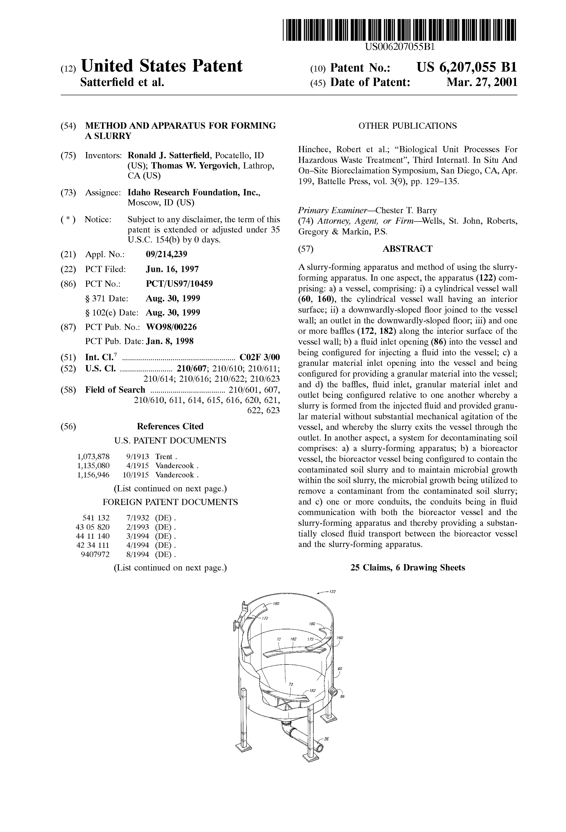
(22) PCT Filed: Jun. 16, 1997 A slurry-forming apparatus and method of using the Slurry forming apparatus. In one aspect, the apparatus (122) com (86) PCT No.: PCT/US97/10459 prising: a) a vessel, comprising: i) a cylindrical vessel wall S371 Date: Aug. 30, 1999 (60, 160), the cylindrical vessel wall having an interior S 102(e) Date: Aug. 30, 1999 Surface; ii) a downwardly-sloped floor joined to the vessel wall; an outlet in the downwardly-sloped floor; iii) and one (87) PCT Pub. No.: WO98/00226 or more baffles (172,182) along the interior surface of the PCT Pub. Date:Jan. 8, 1998 vessel wall; b) a fluid inlet opening (86) into the vessel and (51) Int. Cl." ........................................................ CO2F 3/00 being configured for injecting a fluid into the vessel; c) a (52) U.S. Cl. ... 210/607; 210/610; 210/611; granular material inlet opening into the vessel and being 210/614; 210/616; 210/622; 210/623 configured for providing a granular material into the vessel; (58) Field of Search ..................................... 210/601, 607, and d) the baffles, fluid inlet, granular material inlet and 210/610, 611, 614, 615, 616, 620, 621, outlet being configured relative to one another whereby a 622, 623 Slurry is formed from the injected fluid and provided granu lar material without Substantial mechanical agitation of the (56) References Cited vessel, and whereby the slurry exits the vessel through the
comprises: a) a slurry-forming apparatus; b) a bioreactor 1,073,878 9/1913 Trent. vessel, the bioreactor vessel being configured to contain the 1,135,080 4/1915 Vandercook. contaminated Soil slurry and to maintain microbial growth
within the soil slurry, the microbial growth being utilized to
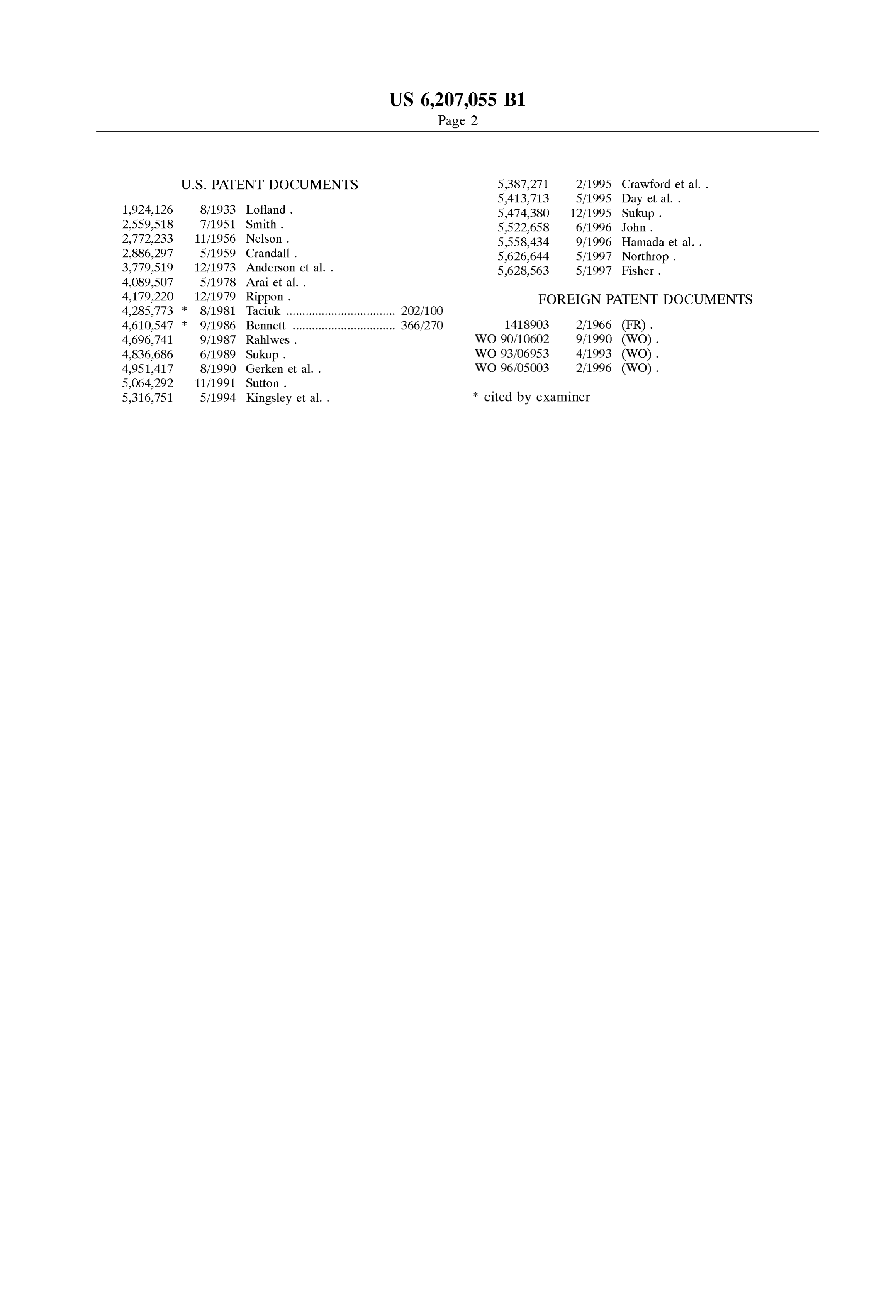
(List continued on next page.) remove a contaminant from the contaminated Soil slurry; FOREIGN PATENT DOCUMENTS and c) one or more conduits, the conduits being in fluid communication with both the bioreactor vessel and the 541 132 7/1932 (DE). Slurry-forming apparatus and thereby providing a Substan
4411 140 3/1994 (DE). tially closed fluid transport between the bioreactor vessel 42 34 111 4/1994 (DE). and the slurry-forming apparatus.
(List continued on next page.) 25 Claims, 6 Drawing Sheets
Page 2
1924,126 8/1933 Lofland. 5,474,380 12/1995 Sukup. 2,559,518 7/1951 Smith. 5,522,658 6/1996 John. 2,772,233 11/1956 Nelson. 5,558,434 9/1996 Hamada et al.. 2,886.297 5/1959 Crandall. 5,626,644 5/1997 Northrop. 3,779,519 12/1973 Anderson et al.. 5,628,563 5/1997 Fisher.
4,179,220 12/1979 Rippon. FOREIGN PATENT DOCUMENTS 4,285,773 8/1981 Taciuk .................................. 202/100 4,610,547 9/1986 Bennett ................................ 366/270 1418903 2/1966 (FR). 4,696,741 9/1987 Rahlwes. WO 90/10602 9/1990 (WO). 4,836,686 6/1989 Sukup. WO 93/06953 4/1993 (WO). 4,951,417 8/1990 Gerken et al. . WO 96/O5003 2/1996 (WO).
5,316,751 5/1994 Kingsley et al.. * cited by examiner
Page 3
Drawing sheet — no readable text.
Page 4
Drawing sheet — no readable text.
Page 5
Drawing sheet — no readable text.
Page 6
Drawing sheet — no readable text.
Page 7
Drawing sheet — no readable text.
Page 8
Drawing sheet — no readable text.
Page 9
METHOD AND APPARATUS FOR FORMING larly likely to occur during transport of the contaminated A SLURRY Soil, as the Soil may become a dust which is wind-blown to clean areas, or may be dribbled from open containers, or
TECHNICAL FIELD trucks, passing over the clean areas. Accordingly, it would The invention pertains to methods and apparatuses for be desirable to develop methods and apparatuses which forming a Slurry. The invention is thought to have particular minimize Spread of contaminated Soil from a remediation relevance to applications in which a contaminated Soil is to Site during a remediation process. be decontaminated through biological activity. Yet another set of problems facing those who would remediate contaminated Soil sites arises from the remote
BACKGROUND ART locations of the Sites. Frequently, Such sites lack access to Major efforts are currently being expended to clean up electrical power and lack nearby facilities for repair of contaminated Soils throughout the United States and the broken minimize equipment. Accordingly, it would be desirable to the power requirements of decontamination appa
World. Such contaminated Soils typically arise as industrial ratuses utilized at the Sites, and to provide relatively durable products or by-products which are spilled either inadvert 15 ently or purposely into the environment. Commonly found decontamination apparatuses.
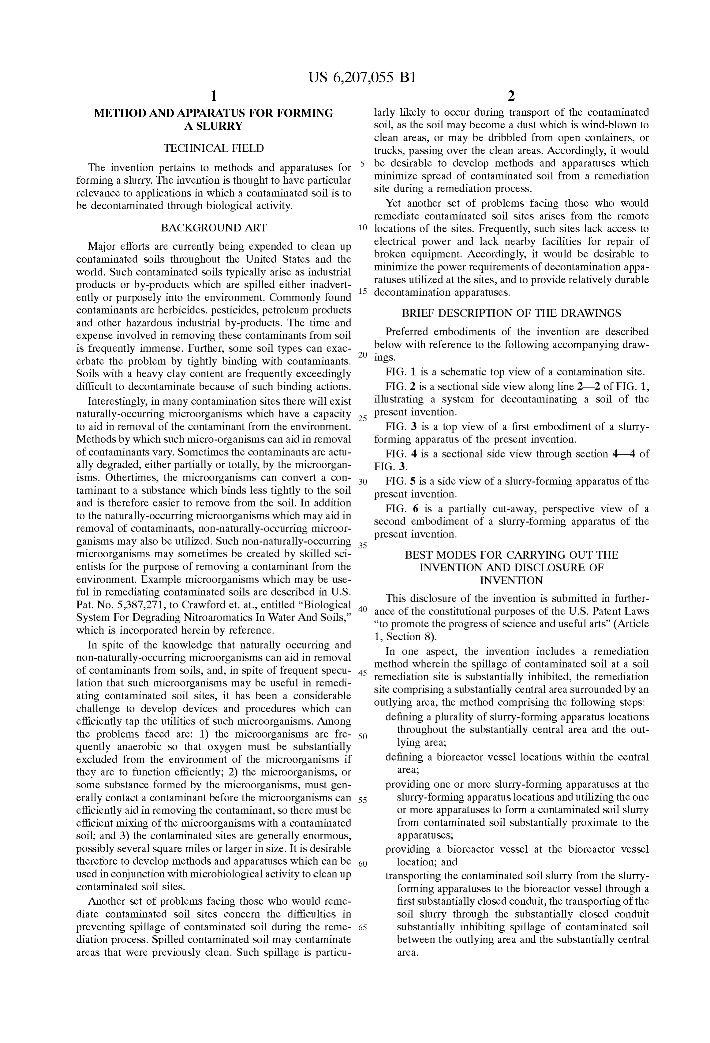
contaminants are herbicides. pesticides, petroleum products BRIEF DESCRIPTION OF THE DRAWINGS and other hazardous industrial by-products. The time and Preferred embodiments of the invention are described expense involved in removing these contaminants from Soil is frequently immense. Further, Some Soil types can exac ings. below with reference to the following accompanying draw erbate the problem by tightly binding with contaminants.
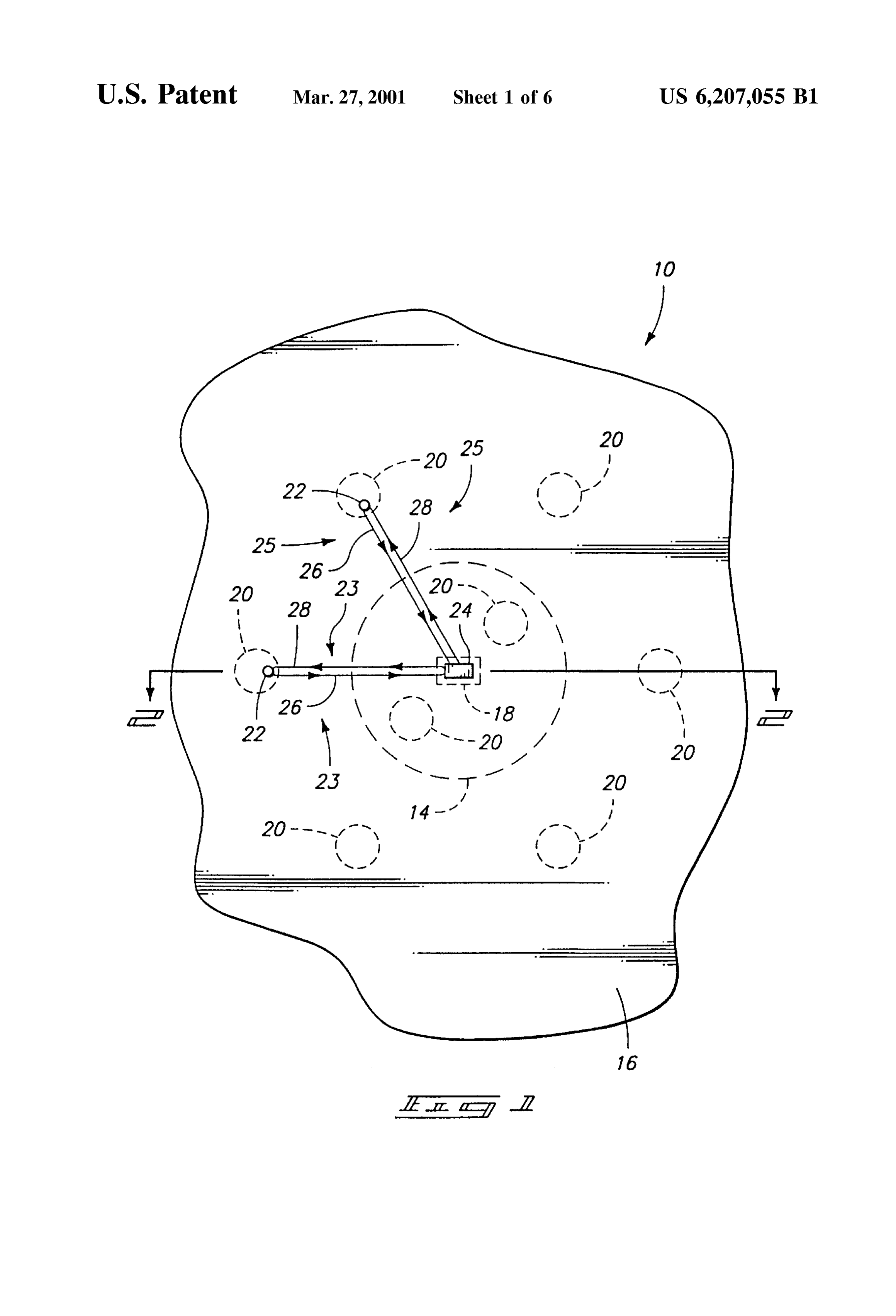
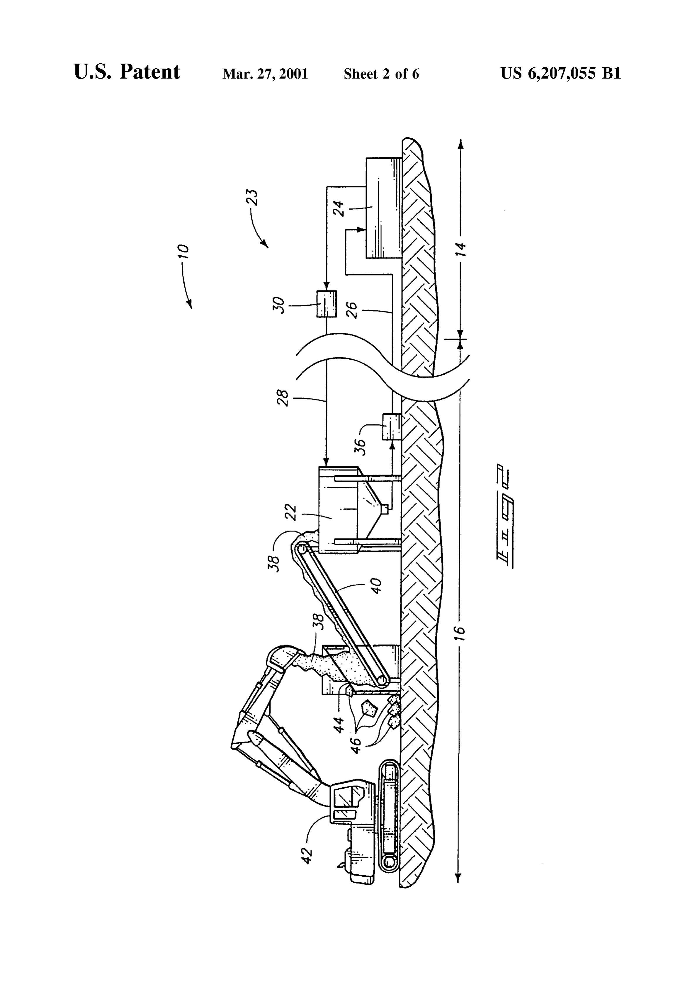
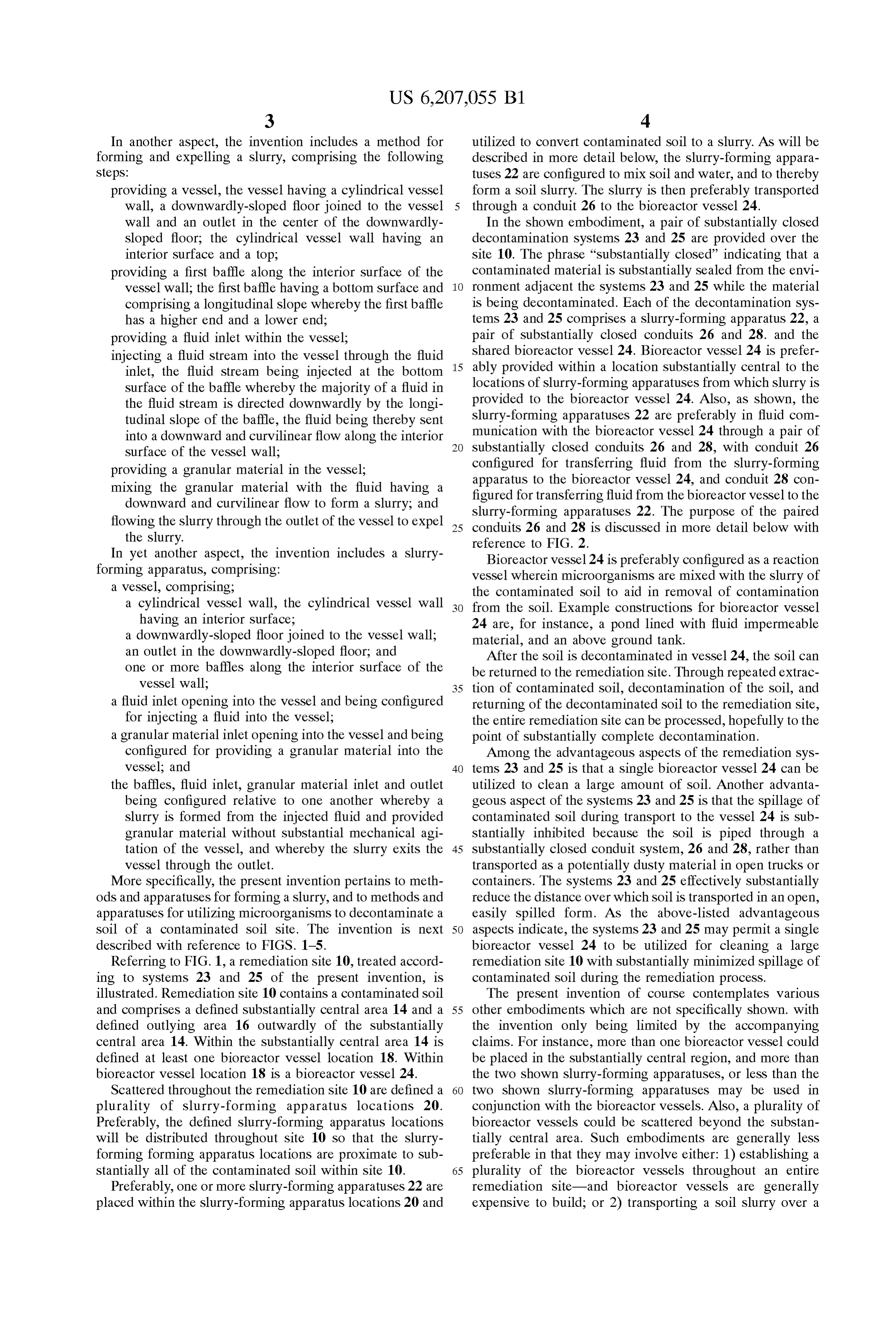
Soils with a heavy clay content are frequently exceedingly FIG. 1 is a Schematic top view of a contamination Site. difficult to decontaminate because of Such binding actions. FIG. 2 is a sectional side view along line 2-2 of FIG. 1, Interestingly, in many contamination Sites there will exist illustrating a System for decontaminating a Soil of the naturally-occurring microorganisms which have a capacity 25 present invention.
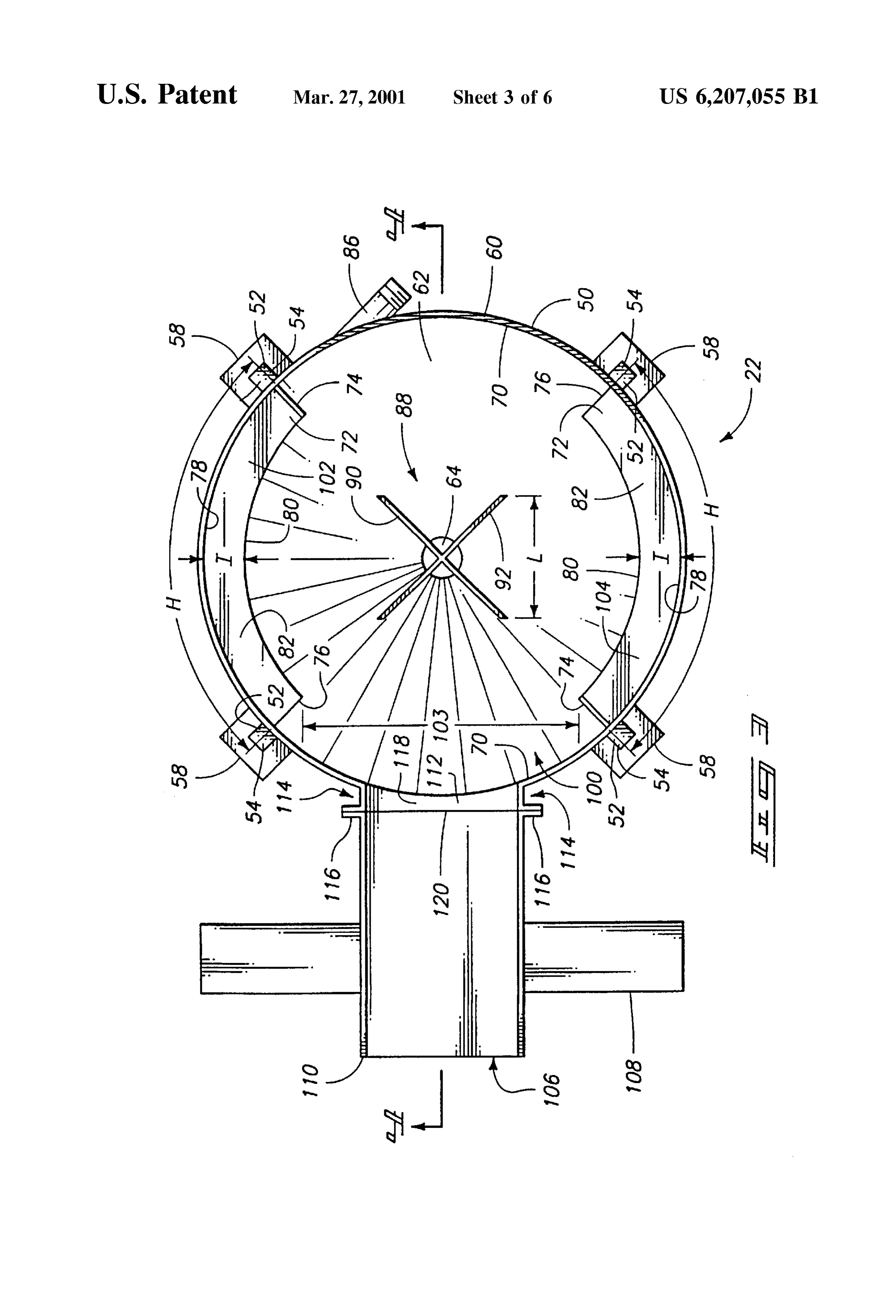
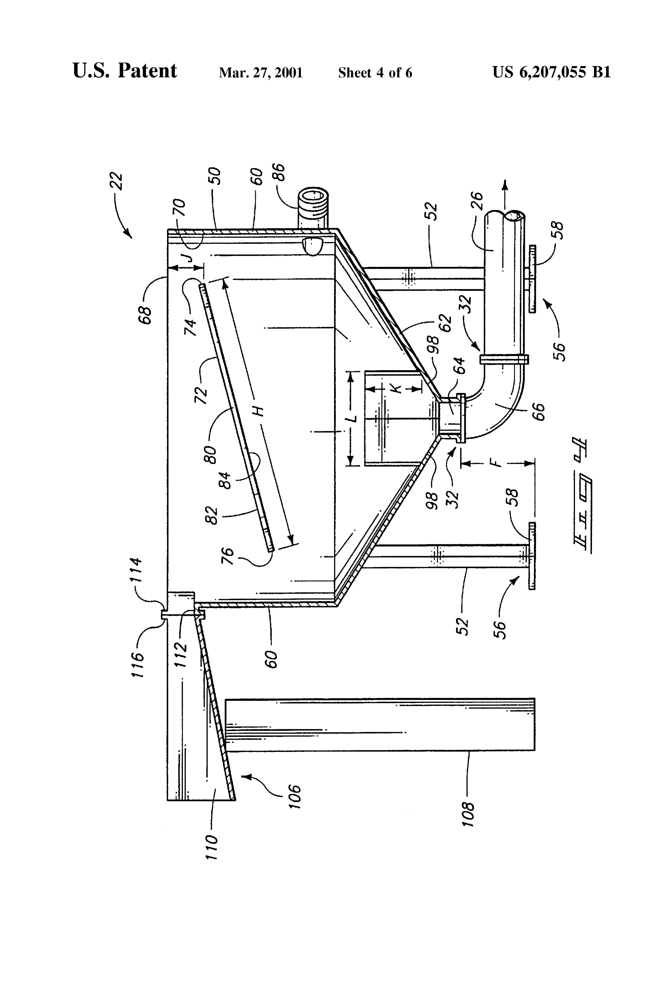
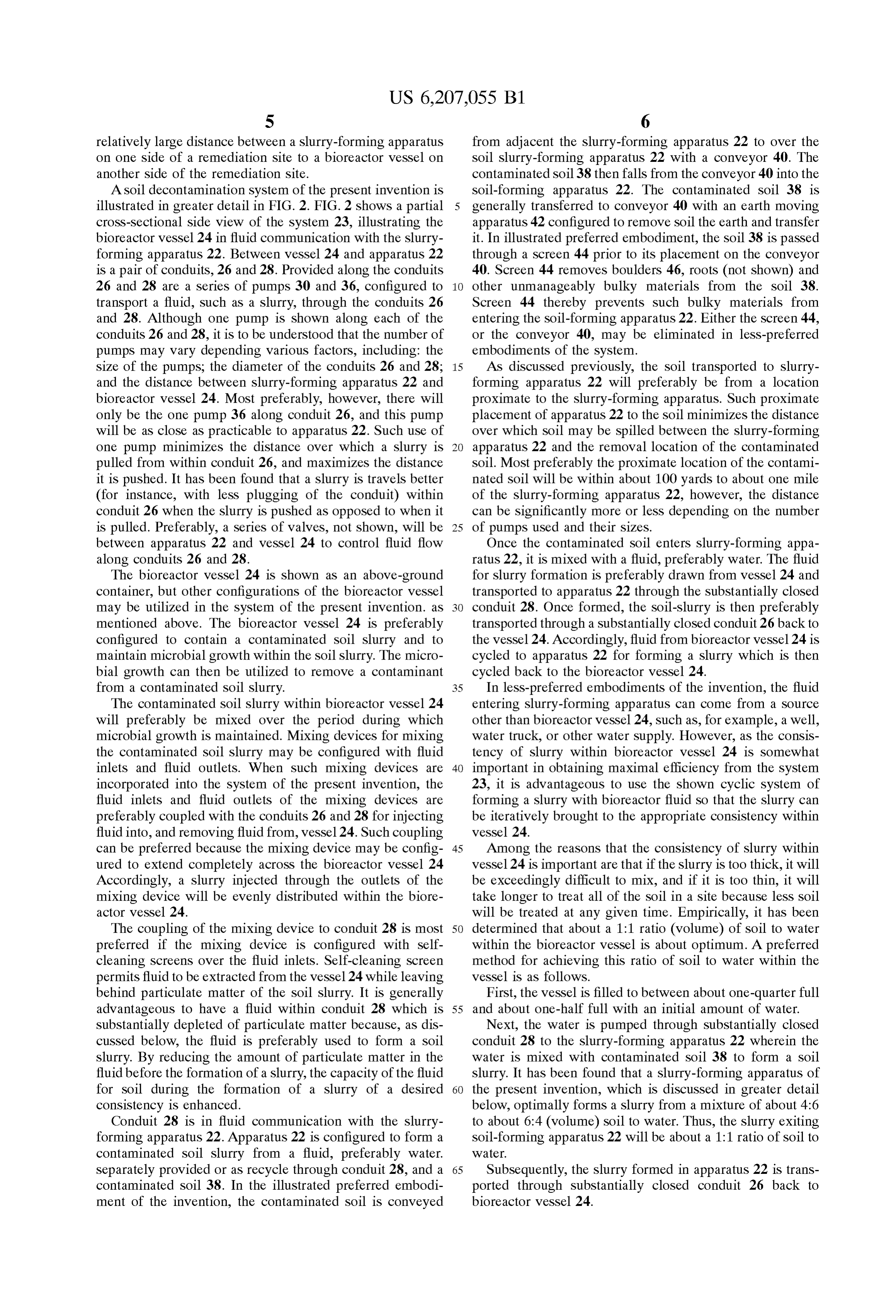
to aid in removal of the contaminant from the environment. FIG. 3 is a top view of a first embodiment of a slurry Methods by which Such micro-organisms can aid in removal forming apparatus of the present invention. of contaminants vary. Sometimes the contaminants are actu FIG. 4 is a sectional side view through section 4-4 of ally degraded, either partially or totally, by the microorgan FIG. 3.
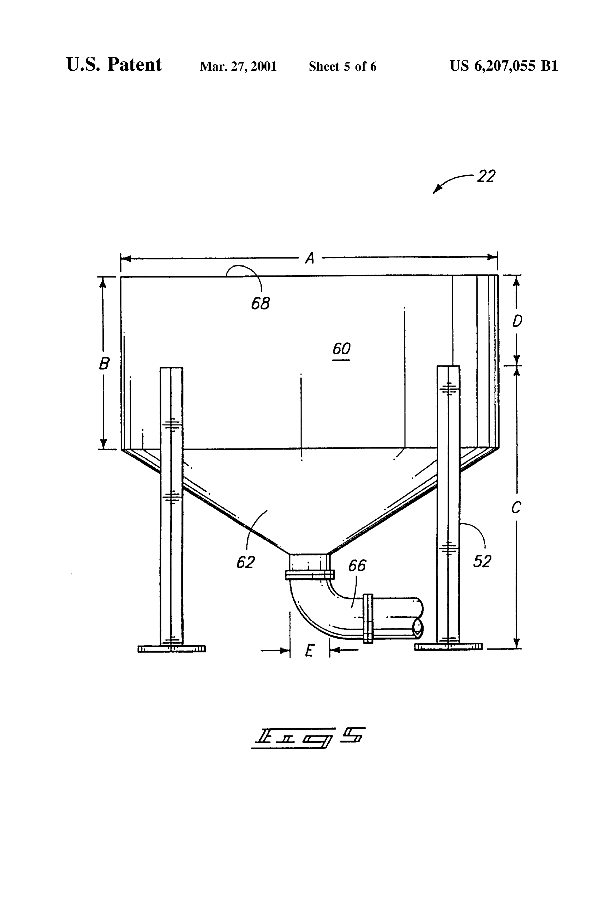
isms. Othertimes, the microorganisms can convert a con FIG. 5 is a side view of a slurry-forming apparatus of the taminant to a Substance which binds less tightly to the Soil present invention.
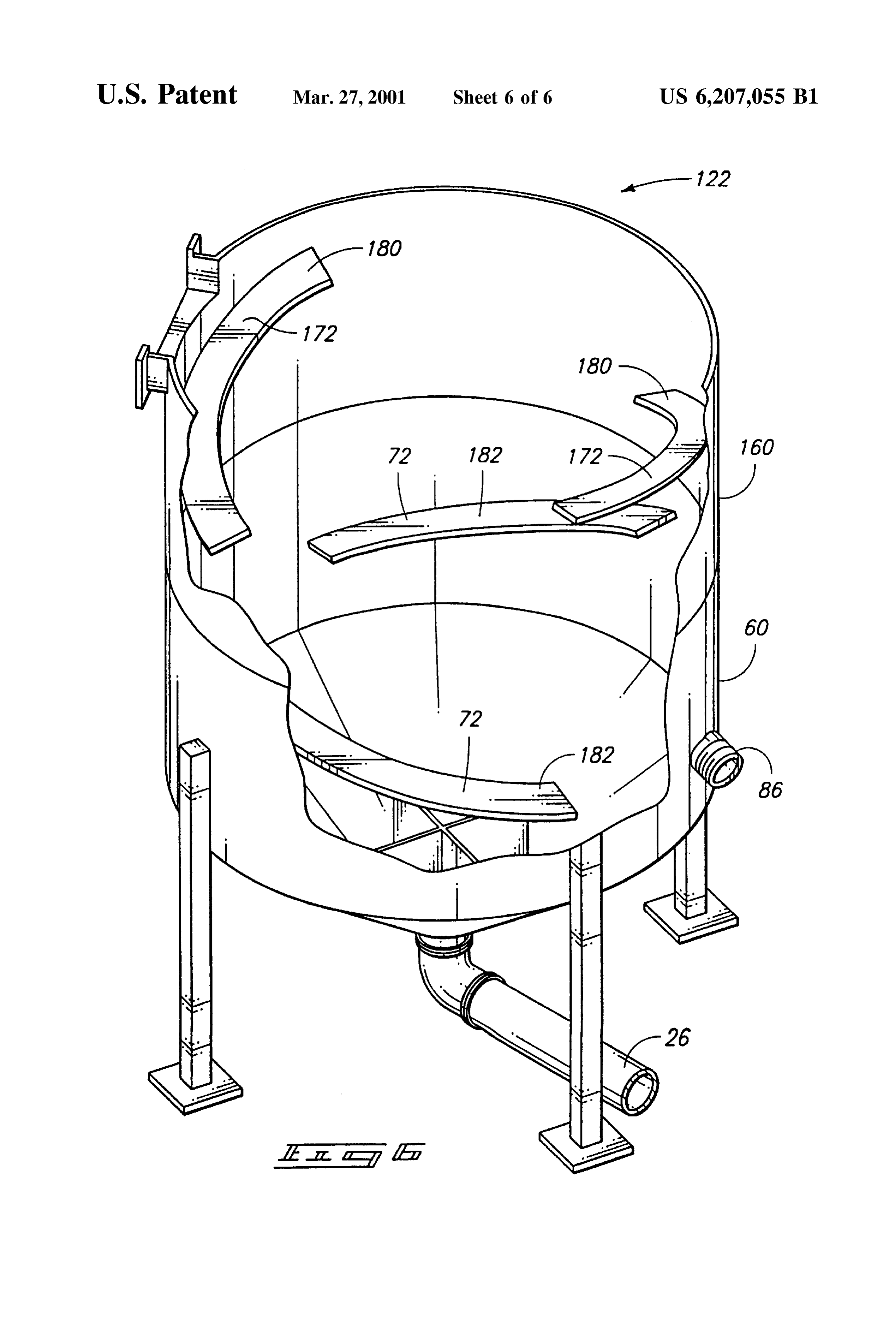
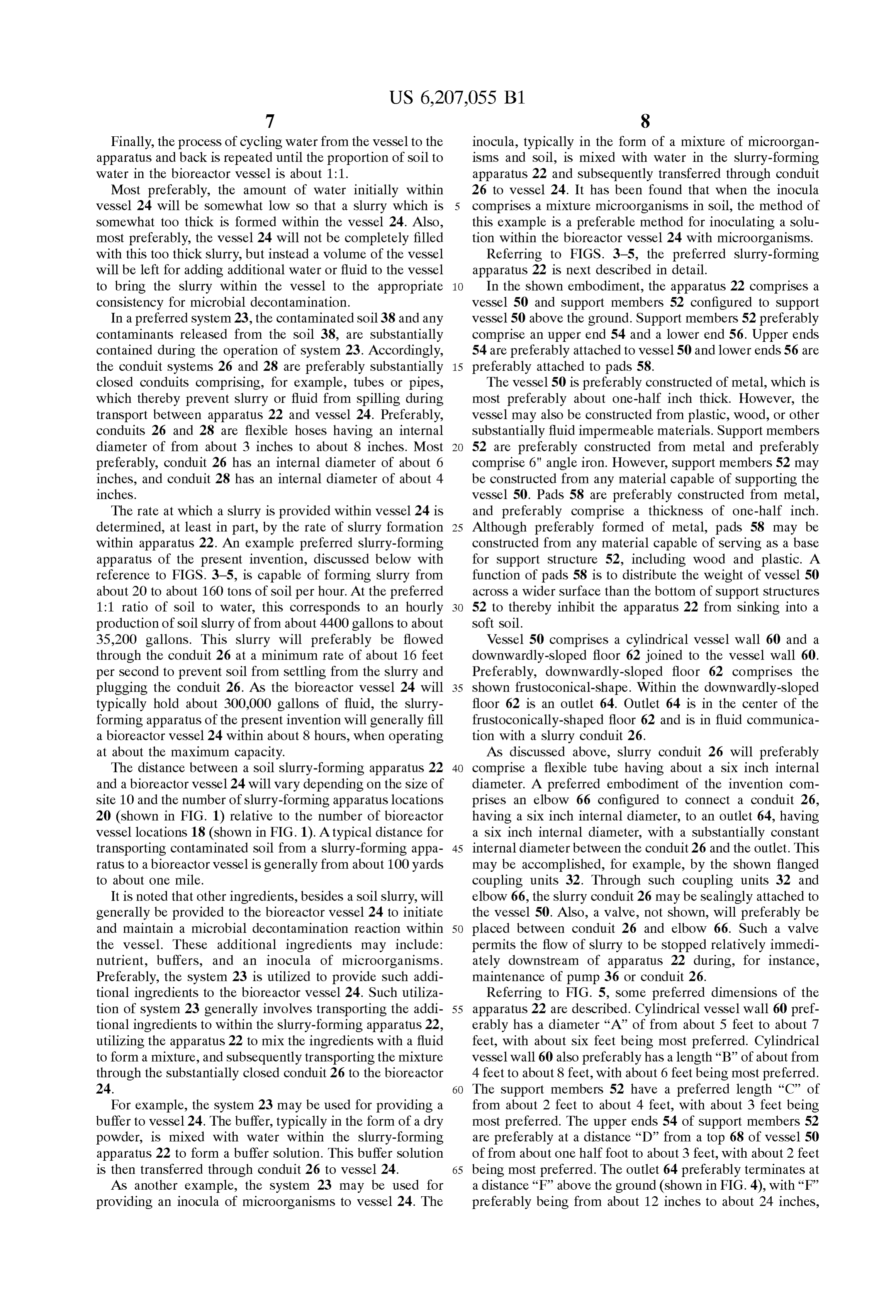
and is therefore easier to remove from the soil. In addition to the naturally-occurring microorganisms which may aid in Second FIG. 6 is a partially cut-away, perspective view of a embodiment of a slurry-forming apparatus of the removal of contaminants, non-naturally-occurring microor present invention.
ganisms may also be utilized. Such non-naturally-occurring 35 microorganisms may Sometimes be created by skilled Sci BEST MODES FOR CARRYING OUT THE entists for the purpose of removing a contaminant from the INVENTION AND DISCLOSURE OF environment. Example microorganisms which may be use INVENTION ful in remediating contaminated Soils are described in U.S. This disclosure of the invention is Submitted in further Pat. No. 5,387,271, to Crawford et. at., entitled “Biological 40 ance of the constitutional purposes of the U.S. Patent Laws System For Degrading Nitroaromatics In Water And Soils,” “to promote the progress of Science and useful arts” (Article which is incorporated herein by reference.
In Spite of the knowledge that naturally occurring and 1, In Section 8).
one aspect, the invention includes a remediation non-naturally-occurring microorganisms can aid in removal method wherein the Spillage of contaminated Soil at a Soil of contaminants from Soils, and, in spite of frequent specu 45 remediation site is Substantially inhibited, the remediation lation that Such microorganisms may be useful in remedi Site comprising a Substantially central area Surrounded by an ating contaminated Soil Sites, it has been a considerable challenge to develop devices and procedures which can outlying area, the method comprising the following Steps: defining a plurality of slurry-forming apparatus locations efficiently tap the utilities of Such microorganisms. Among the problems faced are: 1) the microorganisms are fre 50 throughout the Substantially central area and the out quently anaerobic So that oxygen must be Substantially lying area;
excluded from the environment of the microorganisms if defining a bioreactor vessel locations within the central they are to function efficiently; 2) the microorganisms, or area,
Some Substance formed by the microorganisms, must gen providing one or more Slurry-forming apparatuses at the erally contact a contaminant before the microorganisms can 55 Slurry-forming apparatus locations and utilizing the one efficiently aid in removing the contaminant, So there must be or more apparatuses to form a contaminated Soil slurry efficient mixing of the microorganisms with a contaminated from contaminated Soil Substantially proximate to the Soil; and 3) the contaminated Sites are generally enormous, apparatuSeS, possibly Several Square miles or larger in size. It is desirable providing a bioreactor vessel at the bioreactor vessel therefore to develop methods and apparatuses which can be 60 location; and used in conjunction with microbiological activity to clean up transporting the contaminated Soil slurry from the Slurry contaminated Soil Sites. forming apparatuses to the bioreactor vessel through a Another Set of problems facing those who would reme first Substantially closed conduit, the transporting of the diate contaminated Soil Sites concern the difficulties in Soil Slurry through the Substantially closed conduit preventing Spillage of contaminated Soil during the reme 65 Substantially inhibiting Spillage of contaminated Soil diation process. Spilled contaminated Soil may contaminate between the outlying area and the Substantially central areas that were previously clean. Such spillage is particu C.
Page 10
In another aspect, the invention includes a method for utilized to convert contaminated Soil to a slurry. AS will be forming and expelling a slurry, comprising the following described in more detail below, the Slurry-forming appara Steps: tuses 22 are configured to mix Soil and water, and to thereby providing a vessel, the vessel having a cylindrical vessel form a soil slurry. The slurry is then preferably transported wall, a downwardly-sloped floor joined to the vessel through a conduit 26 to the bioreactor vessel 24. wall and an outlet in the center of the downwardly In the shown embodiment, a pair of Substantially closed sloped floor; the cylindrical vessel wall having an decontamination systems 23 and 25 are provided over the interior Surface and a top; site 10. The phrase “substantially closed” indicating that a providing a first baffle along the interior Surface of the contaminated material is Substantially Sealed from the envi vessel wall; the first baffle having a bottom surface and ronment adjacent the systems 23 and 25 while the material comprising a longitudinal slope whereby the first baffle is being decontaminated. Each of the decontamination Sys has a higher end and a lower end; tems 23 and 25 comprises a slurry-forming apparatus 22, a providing a fluid inlet within the vessel; pair of Substantially closed conduits 26 and 28. and the injecting a fluid Stream into the vessel through the fluid 15 shared bioreactor vessel 24. Bioreactor vessel 24 is prefer inlet, the fluid Stream being injected at the bottom ably provided within a location substantially central to the surface of the baffle whereby the majority of a fluid in locations of Slurry-forming apparatuses from which Slurry is the fluid stream is directed downwardly by the longi provided to the bioreactor vessel 24. Also, as shown, the tudinal slope of the baffle, the fluid being thereby sent Slurry-forming apparatuses 22 are preferably in fluid com into a downward and curvilinear flow along the interior munication with the bioreactor vessel 24 through a pair of Surface of the vessel wall; substantially closed conduits 26 and 28, with conduit 26 providing a granular material in the vessel; configured for transferring fluid from the slurry-forming mixing the granular material with the fluid having a figured apparatus to the bioreactor vessel 24, and conduit 28 con downward and curvilinear flow to form a slurry; and for transferring fluid from the bioreactor vessel to the Slurry-forming apparatuses 22. The purpose of the paired flowing the slurry through the outlet of the vessel to expel 25 conduits 26 and 28 is discussed in more detail below with the slurry. reference to FIG. 2.
In yet another aspect, the invention includes a slurry Bioreactor vessel 24 is preferably configured as a reaction forming apparatus, comprising: vessel wherein microorganisms are mixed with the Slurry of a Vessel, comprising; the contaminated Soil to aid in removal of contamination a cylindrical vessel wall, the cylindrical vessel wall from the Soil. Example constructions for bioreactor vessel having an interior Surface; 24 are, for instance, a pond lined with fluid impermeable a downwardly-sloped floor joined to the vessel wall; material, and an above ground tank. an outlet in the downwardly-sloped floor, and After the Soil is decontaminated in vessel 24, the Soil can one or more baffles along the interior Surface of the be returned to the remediation Site. Through repeated extrac vessel wall; 35 tion of contaminated Soil, decontamination of the Soil, and a fluid inlet opening into the vessel and being configured returning of the decontaminated Soil to the remediation site, for injecting a fluid into the vessel; the entire remediation site can be processed, hopefully to the a granular material inlet opening into the vessel and being point of Substantially complete decontamination. configured for providing a granular material into the Among the advantageous aspects of the remediation Sys vessel; and 40 tems 23 and 25 is that a single bioreactor vessel 24 can be the baffles, fluid inlet, granular material inlet and outlet utilized to clean a large amount of Soil. Another advanta being configured relative to one another whereby a geous aspect of the Systems 23 and 25 is that the Spillage of slurry is formed from the injected fluid and provided contaminated Soil during transport to the vessel 24 is Sub granular material without Substantial mechanical agi Stantially inhibited because the Soil is piped through a tation of the vessel, and whereby the slurry exits the 45 substantially closed conduit system, 26 and 28, rather than vessel through the outlet. transported as a potentially dusty material in open trucks or More Specifically, the present invention pertains to meth containers. The systems 23 and 25 effectively substantially ods and apparatuses for forming a slurry, and to methods and reduce the distance over which Soil is transported in an open, apparatuses for utilizing microorganisms to decontaminate a easily Spilled form. AS the above-listed advantageous Soil of a contaminated Soil Site. The invention is next 50 aspects indicate, the Systems 23 and 25 may permit a single described with reference to FIGS. 1-5. bioreactor vessel 24 to be utilized for cleaning a large Referring to FIG. 1, a remediation site 10, treated accord remediation site 10 with Substantially minimized spillage of ing to Systems 23 and 25 of the present invention, is contaminated Soil during the remediation process. illustrated. Remediation site 10 contains a contaminated Soil The present invention of course contemplates various and comprises a defined Substantially central area 14 and a 55 other embodiments which are not specifically shown. with defined outlying area 16 outwardly of the substantially the invention only being limited by the accompanying central area 14. Within the substantially central area 14 is claims. For instance, more than one bioreactor vessel could defined at least one bioreactor vessel location 18. Within be placed in the Substantially central region, and more than bioreactor vessel location 18 is a bioreactor vessel 24. the two shown Slurry-forming apparatuses, or less than the Scattered throughout the remediation site 10 are defined a 60 two shown Slurry-forming apparatuses may be used in plurality of Slurry-forming apparatus locations 20. conjunction with the bioreactor vessels. Also, a plurality of Preferably, the defined slurry-forming apparatus locations bioreactor vessels could be Scattered beyond the Substan will be distributed throughout site 10 so that the slurry tially central area. Such embodiments are generally leSS forming forming apparatus locations are proximate to Sub preferable in that they may involve either: 1) establishing a stantially all of the contaminated soil within site 10. 65 plurality of the bioreactor vessels throughout an entire Preferably, one or more Slurry-forming apparatuses 22 are remediation site-and bioreactor vessels are generally placed within the slurry-forming apparatus locations 20 and expensive to build; or 2) transporting a Soil slurry over a
Page 11
S 6 relatively large distance between a slurry-forming apparatus from adjacent the Slurry-forming apparatus 22 to over the on one side of a remediation site to a bioreactor vessel on soil slurry-forming apparatus 22 with a conveyor 40. The another Side of the remediation site. contaminated soil 38 then falls from the conveyor 40 into the A Soil decontamination System of the present invention is Soil-forming apparatus 22. The contaminated Soil 38 is illustrated in greater detail in FIG. 2. FIG. 2 shows a partial generally transferred to conveyor 40 with an earth moving croSS-Sectional Side view of the System 23, illustrating the apparatus 42 configured to remove Soil the earth and transfer bioreactor vessel 24 in fluid communication with the slurry it. In illustrated preferred embodiment, the soil 38 is passed forming apparatus 22. Between vessel 24 and apparatus 22 through a Screen 44 prior to its placement on the conveyor is a pair of conduits, 26 and 28. Provided along the conduits 40. Screen 44 removes boulders 46, roots (not shown) and 26 and 28 are a series of pumps 30 and 36, configured to other unmanageably bulky materials from the soil 38. transport a fluid, Such as a slurry, through the conduits 26 Screen 44 thereby prevents such bulky materials from and 28. Although one pump is shown along each of the entering the Soil-forming apparatus 22. Either the Screen 44, conduits 26 and 28, it is to be understood that the number of or the conveyor 40, may be eliminated in less-preferred pumps may vary depending various factors, including: the embodiments of the system.
size of the pumps; the diameter of the conduits 26 and 28; 15 AS discussed previously, the Soil transported to Slurry and the distance between Slurry-forming apparatus 22 and forming apparatus 22 will preferably be from a location bioreactor vessel 24. Most preferably, however, there will proximate to the Slurry-forming apparatus. Such proximate only be the one pump 36 along conduit 26, and this pump placement of apparatuS 22 to the Soil minimizes the distance will be as close as practicable to apparatus 22. Such use of over which soil may be spilled between the slurry-forming one pump minimizes the distance over which a slurry is apparatus 22 and the removal location of the contaminated pulled from within conduit 26, and maximizes the distance soil. Most preferably the proximate location of the contami it is pushed. It has been found that a slurry is travels better nated soil will be within about 100 yards to about one mile (for instance, with less plugging of the conduit) within of the Slurry-forming apparatus 22, however, the distance conduit 26 when the Slurry is pushed as opposed to when it can be significantly more or leSS depending on the number is pulled. Preferably, a series of valves, not shown, will be 25 of pumps used and their sizes.
between apparatus 22 and vessel 24 to control fluid flow Once the contaminated Soil enterS Slurry-forming appa along conduits 26 and 28. ratus 22, it is mixed with a fluid, preferably water. The fluid The bioreactor vessel 24 is shown as an above-ground for slurry formation is preferably drawn from vessel 24 and container, but other configurations of the bioreactor vessel transported to apparatus 22 through the Substantially closed may be utilized in the System of the present invention. as conduit 28. Once formed, the soil-slurry is then preferably mentioned above. The bioreactor vessel 24 is preferably transported through a Substantially closed conduit 26 back to configured to contain a contaminated Soil slurry and to the vessel 24. Accordingly, fluid from bioreactor vessel 24 is maintain microbial growth within the Soil slurry. The micro cycled to apparatus 22 for forming a slurry which is then bial growth can then be utilized to remove a contaminant cycled back to the bioreactor vessel 24.
from a contaminated Soil slurry. 35 In less-preferred embodiments of the invention, the fluid The contaminated soil slurry within bioreactor vessel 24 entering slurry-forming apparatus can come from a Source will preferably be mixed over the period during which other than bioreactor vessel 24, Such as, for example, a well, microbial growth is maintained. Mixing devices for mixing water truck, or other water Supply. However, as the consis the contaminated Soil Slurry may be configured with fluid tency of slurry within bioreactor vessel 24 is somewhat inlets and fluid outlets. When such mixing devices are 40 important in obtaining maximal efficiency from the System incorporated into the System of the present invention, the 23, it is advantageous to use the shown cyclic System of fluid inlets and fluid outlets of the mixing devices are forming a slurry with bioreactor fluid So that the slurry can preferably coupled with the conduits 26 and 28 for injecting be iteratively brought to the appropriate consistency within fluid into, and removing fluid from, Vessel 24. Such coupling vessel 24.
can be preferred because the mixing device may be config 45 Among the reasons that the consistency of slurry within ured to extend completely across the bioreactor vessel 24 vessel 24 is important are that if the slurry is too thick, it will Accordingly, a slurry injected through the outlets of the be exceedingly difficult to mix, and if it is too thin, it will mixing device will be evenly distributed within the biore take longer to treat all of the Soil in a site because leSS Soil actor vessel 24. will be treated at any given time. Empirically, it has been The coupling of the mixing device to conduit 28 is most 50 determined that about a 1:1 ratio (volume) of soil to water preferred if the mixing device is configured with Self within the bioreactor vessel is about optimum. A preferred cleaning Screens over the fluid inlets. Self-cleaning Screen method for achieving this ratio of soil to water within the permits fluid to be extracted from the vessel 24 while leaving vessel is as follows.
behind particulate matter of the Soil slurry. It is generally First, the vessel is filled to between about one-quarter full advantageous to have a fluid within conduit 28 which is 55 and about one-half full with an initial amount of water. Substantially depleted of particulate matter because, as dis Next, the water is pumped through Substantially closed cussed below, the fluid is preferably used to form a soil conduit 28 to the Slurry-forming apparatus 22 wherein the Slurry. By reducing the amount of particulate matter in the water is mixed with contaminated Soil 38 to form a soil fluid before the formation of a slurry, the capacity of the fluid Slurry. It has been found that a slurry-forming apparatus of for Soil during the formation of a slurry of a desired 60 the present invention, which is discussed in greater detail consistency is enhanced. below, optimally forms a slurry from a mixture of about 4:6 Conduit 28 is in fluid communication with the slurry to about 6:4 (volume) soil to water. Thus, the slurry exiting forming apparatus 22. Apparatus 22 is configured to form a Soil-forming apparatus 22 will be about a 1:1 ratio of Soil to contaminated Soil slurry from a fluid, preferably water. Water.
Separately provided or as recycle through conduit 28, and a 65 Subsequently, the Slurry formed in apparatus 22 is trans contaminated soil 38. In the illustrated preferred embodi ported through Substantially closed conduit 26 back to ment of the invention, the contaminated Soil is conveyed bioreactor vessel 24.
Page 12
Finally, the process of cycling water from the vessel to the inocula, typically in the form of a mixture of microorgan apparatus and back is repeated until the proportion of Soil to isms and Soil, is mixed with water in the slurry-forming water in the bioreactor vessel is about 1:1. apparatus 22 and Subsequently transferred through conduit Most preferably, the amount of water initially within 26 to vessel 24. It has been found that when the inocula vessel 24 will be somewhat low so that a slurry which is comprises a mixture microorganisms in Soil, the method of Somewhat too thick is formed within the vessel 24. Also, this example is a preferable method for inoculating a Solu most preferably, the vessel 24 will not be completely filled tion within the bioreactor vessel 24 with microorganisms. with this too thick slurry, but instead a volume of the vessel Referring to FIGS. 3-5, the preferred slurry-forming will be left for adding additional water or fluid to the vessel apparatus 22 is next described in detail. to bring the slurry within the vessel to the appropriate In the shown embodiment, the apparatuS 22 comprises a consistency for microbial decontamination. vessel 50 and support members 52 configured to support In a preferred system 23, the contaminated soil 38 and any vessel 50 above the ground. Support members 52 preferably contaminants released from the soil 38, are substantially comprise an upper end 54 and a lower end 56. Upper ends contained during the operation of System 23. Accordingly, 54 are preferably attached to vessel 50 and lower ends 56 are the conduit systems 26 and 28 are preferably substantially 15 preferably attached to pads 58.
closed conduits comprising, for example, tubes or pipes, The vessel 50 is preferably constructed of metal, which is which thereby prevent slurry or fluid from spilling during most preferably about one-half inch thick. However, the transport between apparatus 22 and vessel 24. Preferably, vessel may also be constructed from plastic, wood, or other conduits 26 and 28 are flexible hoses having an internal Substantially fluid impermeable materials. Support members diameter of from about 3 inches to about 8 inches. Most 52 are preferably constructed from metal and preferably preferably, conduit 26 has an internal diameter of about 6 comprise 6" angle iron. However, Support members 52 may inches, and conduit 28 has an internal diameter of about 4 be constructed from any material capable of Supporting the inches. vessel 50. Pads 58 are preferably constructed from metal, The rate at which a slurry is provided within vessel 24 is and preferably comprise a thickness of one-half inch. determined, at least in part, by the rate of Slurry formation 25 Although preferably formed of metal, pads 58 may be within apparatus 22. An example preferred slurry-forming constructed from any material capable of Serving as a base apparatus of the present invention, discussed below with for Support Structure 52, including wood and plastic. A reference to FIGS. 3-5, is capable of forming slurry from function of pads 58 is to distribute the weight of vessel 50 about 20 to about 160 tons of soil per hour. At the preferred acroSS a wider Surface than the bottom of Support Structures 1:1 ratio of Soil to water, this corresponds to an hourly 52 to thereby inhibit the apparatus 22 from sinking into a production of soil slurry of from about 4400 gallons to about Soft Soil.
35,200 gallons. This slurry will preferably be flowed Vessel 50 comprises a cylindrical vessel wall 60 and a through the conduit 26 at a minimum rate of about 16 feet downwardly-sloped floor 62 joined to the vessel wall 60. per Second to prevent Soil from Settling from the Slurry and Preferably, downwardly-sloped floor 62 comprises the plugging the conduit 26. AS the bioreactor vessel 24 will 35 shown frustoconical-shape. Within the downwardly-sloped typically hold about 300,000 gallons of fluid, the slurry floor 62 is an outlet 64. Outlet 64 is in the center of the forming apparatus of the present invention will generally fill frustoconically-shaped floor 62 and is in fluid communica a bioreactor vessel 24 within about 8 hours, when operating tion with a slurry conduit 26.
at about the maximum capacity. As discussed above, slurry conduit 26 will preferably The distance between a Soil slurry-forming apparatus 22 40 comprise a flexible tube having about a six inch internal and a bioreactor vessel 24 will vary depending on the size of diameter. A preferred embodiment of the invention com Site 10 and the number of slurry-forming apparatus locations prises an elbow 66 configured to connect a conduit 26, 20 (shown in FIG. 1) relative to the number of bioreactor having a six inch internal diameter, to an outlet 64, having vessel locations 18 (shown in FIG. 1). A typical distance for a six inch internal diameter, with a Substantially constant transporting contaminated Soil from a slurry-forming appa 45 internal diameter between the conduit 26 and the outlet. This ratus to a bioreactor vessel is generally from about 100 yards may be accomplished, for example, by the shown flanged to about one mile. coupling units 32. Through Such coupling units 32 and It is noted that other ingredients, besides a Soil slurry, will elbow 66, the slurry conduit 26 may be sealingly attached to generally be provided to the bioreactor vessel 24 to initiate the vessel 50. Also, a valve, not shown, will preferably be and maintain a microbial decontamination reaction within 50 placed between conduit 26 and elbow 66. Such a valve the vessel. These additional ingredients may include: permits the flow of slurry to be stopped relatively immedi nutrient, buffers, and an inocula of microorganisms. ately downstream of apparatus 22 during, for instance, Preferably, the system 23 is utilized to provide such addi maintenance of pump 36 or conduit 26.
tional ingredients to the bioreactor vessel 24. Such utiliza Referring to FIG. 5, some preferred dimensions of the tion of System 23 generally involves transporting the addi 55 apparatus 22 are described. Cylindrical vessel wall 60 pref tional ingredients to within the Slurry-forming apparatus 22, erably has a diameter “A” of from about 5 feet to about 7 utilizing the apparatus 22 to mix the ingredients with a fluid feet, with about six feet being most preferred. Cylindrical to form a mixture, and Subsequently transporting the mixture vessel wall 60 also preferably has a length “B” of about from through the substantially closed conduit 26 to the bioreactor 4 feet to about 8 feet, with about 6 feet being most preferred. 24. 60 The support members 52 have a preferred length “C” of For example, the System 23 may be used for providing a from about 2 feet to about 4 feet, with about 3 feet being buffer to vessel 24. The buffer, typically in the form of a dry most preferred. The upper ends 54 of support members 52 powder, is mixed with water within the Slurry-forming are preferably at a distance “D” from a top 68 of vessel 50 apparatus 22 to form a buffer solution. This buffer solution of from about one half foot to about 3 feet, with about 2 feet is then transferred through conduit 26 to vessel 24. 65 being most preferred. The outlet 64 preferably terminates at AS another example, the System 23 may be used for a distance “F” above the ground (shown in FIG. 4), with “F” providing an inocula of microorganisms to vessel 24. The preferably being from about 12 inches to about 24 inches,
Page 13
with about 19 inches being most preferred. Also, outlet 64 Preferably, fluid inlet 86 is oriented to inject a fluid into preferably has a diameter “E” of from about 5 inches to vessel 50 and substantially horizontally, and substantially about 15 inches, with about 6 inches being most preferred. perpendicular to a radius of the cylindrical vessel wall 60. Referring to FIGS. 3 and 4, vessel 50 comprises an The injected fluid preferably Swirls within the vessel 50, and interior Surface 70 and an inner circumference extending preferably is maintained at a level within the vessel which is curvilinearly around the interior surface 70 of the vessel wall a couple of inches above the top surface 82 of a baffle 102. 60. Most preferably, as shown, the inner circumference of The Swirling fluid is directed downwardly by the longitu vessel wall 60 remains constant along the entire length “B” dinal slope of baffle 102 into the vessel 50. As the fluid is (shown in FIG. 5) of the wall 60. directed downwardly by baffle 102, the cylindrical vessel Along the interior surface 70 are one or more baffles 72, wall 60 further directs the fluid curvilinearly within the and most preferably two baffles; a first baffle 102 and a vessel 50. Accordingly, in a most preferred embodiment of second baffle 104. Each of the baffles 72 comprises a baffle the invention, a fluid is injected from fluid inlet 86 and is end 74, an opposite opposing baffle end 76, an outer edge 78, directed into a curvilinear downward flow within the vessel an inner edge 80, an upper Surface 82, and a bottom Surface 84. The baffles further comprise an arcuate length “H” from 15 50.
the baffle end 74 to the opposite opposing baffle end 76, and At the bottom of vessel 50, over the outlet 64. is provided a radially oriented width “I” from the outer edge 78 to the a vortex breaker 88. Vortex breaker 88 comprises a pair of inner opposing edge 80. In a preferred embodiment of the perpendicular members 90 and 92 which extend across invention, cylindrical vessel wall 60 comprises an internal outlet 64. The perpendicular members 90 and 92 cross at diameter of about six feet and each of the two baffles 72 has about a center of outlet 64. The vortex breaker 88 is a radially oriented width “I” of less than about one-tenth of preferably configured to be complementary to the the internal diameter of vessel wall 60, and most preferably downwardly-sloped floor 62 of vessel 50, as shown in FIG. of about Six inches. 4. Accordingly, the vortex breaker 88 preferably comprises The arcuate length “H” of baffles 72 is preferably equal to sloped portions 98 which have a slope parallel to a slope of about one-fourth of the inner circumference of the vessel downwardly sloped floor 62.
wall 60. Most preferably, the first and second baffles 102 and 25 Vortex breaker 88 is preferably formed from a substan 104 each comprises about an identical arcuate length “H” tially rigid material Such as wood, plastic or metal. Vortex which is about equal to one-fourth of the inner circumfer breaker 88 may be mounted to vessel 50 by a number of ence of the cylindrical vessel wall. Also, most preferably the methods known to perSons with skill in the art, including: first and second baffles 102 and 104 are circumferentially welding, adhesion by glue, and adhesion by fastenerS Such Spaced from one another by about a distance of one-fourth as Screws, bolts and rivets.
the inner circumference of vessel wall 60. In less preferred A function of vortex breaker 88 is to interrupt the down embodiments, the baffles 72 may comprise varying lengths ward curvilinear flow of fluid within vessel 50 and to thereby and may be separated by unequal distances. enhance the mixing of Solid particles and fluid within the Baffles 72 are preferably formed from a relatively rigid, vessel 50. Vortex breaker 88 may thus enhance slurry fluid-impermeable material, Such as metal, wood or plastic. 35 formation. Vortex breaker 50 preferably comprises a mini The baffles may be mounted to the interior Surface of vessel mum thickness dimension “K” (FIG. 4) of from about 8 wall 60 by a number of methods known to persons with skill inches to about 20 inches, and most preferably of about 14 in the art. Such methods include: welding, adhesion with inches. The VorteX breaker also preferably comprises a glue, and adhesion with penetrating fastenerS Such as length “L”, of from about 12 inches to about 24 inches, and Screws, bolts or nails. 40 most preferably of about 18 inches. In the shown embodiment, each baffle 72 comprises a Apparatus 22 further comprises a granular material inlet longitudinal Slope So that opposing end 74 is higher than 100 (FIG. 3) which opens into vessel 50 and which is opposite opposing end 76. Preferably the longitudinal Slope configured for provision of a granular material into the will not be 90 from level, more preferably the slope will be vessel 50. In the shown preferred embodiment, the granular from about 10 to about 20 from level, and most preferably 45 material inlet comprises the open top of vessel 50. the longitudinal slope will be about 15 from level. Also Preferably, the granular material inlet will be provided in a preferably, the higher end 74 is a distance “J” (shown in FIG. region 103 (FIG. 3) which extends between the two baffles 4) from the top 68 of vessel 50. Preferably, “J” is from about 72 and which extends from the interior Surface 70 of vessel 3 inches to about 9 inches, and most preferably “J” is about wall 60 to less than about one-third of the internal diameter 6 inches. In a most preferred embodiment of the invention, 50 of vessel wall 60. It is generally undesired to provide the higher end 74 of each of the two baffles 72 is about an granular material directly over opening 64, as the granular equal distance “J” from the top 68 of vessel. material is likely to exit from vessel 50 before it has been A fluid inlet 86 opens into vessel 50 and is configured for Substantially converted to a slurry. Also, it is generally injecting a fluid into the vessel. Fluid inlet 86 will most undesired to have the granular material inlet directly over preferably comprise a tube having about a 4 inch internal 55 one of the baffles 72, as the granular material tends to diameter. In the shown embodiment, vessel inlet 86 extends accumulate on the baffle rather than mixing into a slurry. through the cylindrical vessel wall 60 and terminates flush AS mentioned above, in operation the a fluid injected into with the inside of the vessel wall. Other configurations for vessel 50 preferably is directed substantially downwardly providing a fluid inlet within vessel 50, will be recognized and substantially curvilinearly along the interior surface 70 by persons skilled in the art. Such methods include, for 60 of vessel 50. Some of the injected fluid most preferably example, running a tube or hose over the top of vessel 50 and flows above the first baffle 102, and most preferably flows along the interior surface 70 of the vessel to provide the inlet about 1 to 2 inches above the first baffle 102. Accordingly, within the vessel. Preferably, fluid inlet 86 is connected to in operation there is preferably a fluid level within vessel 50 conduit 28 through a flanged coupling unit analogous to the which most preferably has an upper Surface that is about an flanged coupling units 32. Also preferably, a valve is posi 65 inch or two above the top surface 82 of first baffle 102. Due tioned between pump 30 and inlet 86, most preferably to the cylindrical configuration of vessel 50 and the pressure between the inlet an conduit 28. of injection of fluid within the vessel, the fluid Swirls
Page 14
curvilinearly within vessel 50 and approaches upper end 74 embodiment of the invention and comprises four baffles 172 of the second baffle 104. As discussed previously, second Spaced circumferentially within the apparatus. The appara baffle 104 will most preferably have a 15 slope identical to tuS 122 may be thought of as being formed by Stacking a the slope of first baffle 102. Accordingly, the fluid approach second cylindrical wall 160 of length “B” (length “B” is ing second baffle 104 will be generally forced downwardly shown in FIG. 5) atop the first cylindrical wall 60 shown in by the longitudinal slope of second baffle 104. FIGS. 4 and 5. The second cylindrical wall 60 preferably AS the above discussion indicates, a net effect of the two comprises the same preferable construction as the first vessel baffles 72 and cylindrical wall 60 is to force a fluid within wall 60, discussed above, and preferably has a pair of baffles apparatus 22 in a downward curvilinear flow. The downward 172 attached within an interior of the wall 160 in the same curvilinear flow of the fluid is substantially countered, preferred orientation illustrated for baffles 72 within wall 60 however, by the vortex breaker 88 at the bottom of the vessel (the preferred orientation of baffles 72 within wall 60 is 50 So that a vigorous mixing action occurs within the vessel shown in FIG. 4). The second cylindrical wall 160 is to thereby form a slurry. Once formed, the slurry eventually preferably rotated 90° relative to wall 60. Thus, the appa finds a way to the outlet 64, whereby the slurry exits the ratus 122 comprises an upper pair of baffles 180 and a lower vessel 50. 15 pair of baffles 182, with the upper pair of baffles being When a soil slurry is formed with apparatus 22, Soil will circumferentially displaced relative to the lower pair of preferably be mixed with the fluid water. The rates of water baffles.
flow and soil flow will preferably be controlled to maintain In the shown preferred embodiment, there is no granular a ratio of Soil to water within the apparatus in a range of from material opening analogous to the opening 103 (shown in about 4:6 to about 6:4, at which range it has been found that FIG. 3) which is not over a baffle, so the granular material the most efficient Slurry formation occurs. At higher ratios of is generally input over a baffle. AS discussed previously Soil to water, the Slurry tends to be thick and accordingly regarding the vessel 22, this may create Some problems with difficult to flow through conduit 26. At lower ratios of soil granular material accumulating on a baffle. However, ideally to water, the Soil-slurry tends to be thin Such that it takes the fluid level within apparatus 122 will be maintained longer to make a quantity of slurry then it does at the 25 within a few inches of upper baffles 180, so if granular preferred ratioS. material is input over lower baffles 182 the granular material An example preferred water injection rate for forming a generally will not accumulate on the baffles. soil slurry in the shown apparatus 22 is from about 7000 A slurry-forming apparatus of the present invention is gallons/hour to about 20,000 gallons/hour, and a most pref thought to be particularly well adapted to Soil remediation erably is about 13,000 gallons/hour. An example preferred processes in that the apparatus does not required Substantial soil provision rate for the apparatus 22 is from about 900 mechanical agitation to form a slurry. Accordingly, there is cubic feet/hour to about 2700 cubic feet/hour. no need for moving mechanical parts, in the apparatus itself, After the Slurry is formed, it exits vessel 50 at a slurry which may Substantially reduce the likelihood of wear of the removal rate. The slurry removal rate can be controlled apparatus, thereby potentially increasing the uSable lifetime somewhat by having the slurry enter a conduit 26 which is 35 of the apparatus and reducing the need for repair of the connected to a pump, and controlling the pumping rate. apparatus. Also, the lack of moving mechanical parts effec Preferably, the slurry removal rate and the fluid injection rate tively eliminates a need to provide power to the apparatus of are controlled to maintain a Substantially constant Volume of the present invention, which may make the apparatus par fluid within the vessel, with the top of the fluid at the most ticularly Suitable for use in remote locations. Additionally, preferred level discussed previously. Under such preferable 40 the durable, effectively one-piece construction of the pre conditions, a Substantially continuous Stream of Slurry may ferred apparatus may enable the apparatus to be transported be formed with the apparatus. A preferred slurry removal to varying locations in a remediation site and utilized with rate is 16 feet per Second. minimal Set up effort.
Due to the contaminated nature of the Soil entering It is noted that an apparatus of the present invention may Slurry-forming apparatus 22, the fluid within the apparatus is 45 have utility beyond Soil-slurry formation. For instance, it has generally contaminated. Thus, it is most preferred that the been found experimentally that the apparatus may have Slurry removal rate and fluid injection rate be controlled to utility for Washing a Soil. Specifically, a contaminated Soil substantially prevent fluid from spilling over the top of Subjected to mixing within the Slurry-forming device of the vessel wall 60. The spill-over of contaminated fluid from present invention can Sometimes be washed of contaminate vessel 50 can also be substantially reduced by increasing the 50 to form a relatively decontaminated Soil and a contaminated distance “J” from the top of baffles 72 to the top 68 of vessel wash Solution. In Such cases, the relatively decontaminated 50. Soil can be separated from the wash Solution and returned to In the embodiment shown in FIGS. 3 and 4, a safeguard the environment. The wash Solution can then be transferred, device is attached to the apparatus 22 to channel fluid for example, through a conduit System, to a bioreactor vessel overflow and to thereby reduce the risk of uncontrolled 55 wherein the Solution is treated to remove contamination. Spill-over of contaminated fluid from the apparatus 22. This process would be advantageous Over processes wherein Safeguard device 106 consists of a support structure 108 and an entire Soil-slurry is transferred to a bioreactor vessel, in a trough 110. Trough 110 is configured a direct overflow that it is generally more expedient to treat a fluid than a fluid from vessel 50 into a desired location (not shown). Slurry, and in that it is generally easier to transfer a fluid Vessel 50 is fluidly connected to trough 110 through a notch 60 through a conduit System than to transfer a slurry through a 112 in the wall 60 of vessel 50. Vessel 50 comprises a pair conduit System.
of flanges 114 adjacent notch 112 and configured for con It is also noted that an apparatus of the present invention necting to a flange 116 joined to trough 110. A fluid channel could have applicability to any applications in which it is 118 extends from notch 112 under an upper portion 120 of desired to eliminate moving mechanical parts from a slurry flange 116 and along trough 110. 65 forming apparatus. Additionally, the apparatus may have Referring to FIG. 6, a second embodiment slurry-forming application to Systems in which mixing is to be done, even apparatus 122 is illustrated. Apparatus 122 is a preferred if Such mixing is to form Something other than a slurry.
Page 15
In compliance with the Statute, the invention has been 8. The method of claim 1 further comprising: described in language more or leSS Specific as to structural providing a slurry conduit in fluid communication with and methodical features. It is to be understood, however that the outlet, the Slurry conduit being a tube Sealingly the invention is not limited to the Specific features shown attached to the vessel; and and described, Since the means herein disclosed comprise pumping the formed slurry through the Slurry conduit. preferred forms of putting the invention into effect. The 9. The method of claim 8 wherein the formed slurry is invention is, therefore, claimed in any of its forms or pumped through the slurry conduit at a rate of equal to or modifications within the proper Scope of the appended greater than about Sixteen feet per Second. claims appropriately interpreted in accordance with the 10. The method of claim 1 wherein the fluid stream is doctrine of equivalents. injected into the vessel at a fluid injection rate, the method What is claimed is:
1. A method for forming and expelling a slurry, compris further comprising:
ing the following Steps: providing a slurry conduit in fluid communication with providing a vessel, the vessel having a cylindrical vessel 15 the outlet;
wall, a downwardly-sloped floor joined to the vessel pumping the slurry through the Slurry conduit at a slurry wall and an outlet in about the center of the removal rate; and downwardly-sloped floor; the cylindrical vessel wall controlling the Slurry removal rate and fluid injection rate having an interior Surface and a top; to maintain a Substantially constant Volume of fluid and providing a first baffle along the interior Surface of the Slurry within the vessel during the Step. vessel wall; the first baffle comprising a longitudinal 11. The method of claim 1 wherein the fluid stream slope; comprises water injected into the vessel at a water injection providing a fluid inlet to within the vessel; rate, and wherein the Soil is provided at a Soil provision rate, injecting a fluid Stream into the vessel through the fluid 25 the Soil provision rate and the water injection rate being inlet, the fluid stream being directed downwardly by together controlled to maintain a ratio of Soil to water within the longitudinal slope of the baffle, the fluid being the apparatus of from about 4:6 to about 6:4 during the thereby sent into a downward and curvilinear flow mixing 12. A
Step.
method for reducing contamination of a contami along the interior Surface of the vessel wall; nated Soil, comprising the following Steps: providing a granular material in the vessel, wherein the transporting the contaminated Soil to within a slurry granular material is a contaminated Soil; forming apparatus;
mixing the granular material with the fluid having a transporting water to within the Slurry-forming apparatus, downward and curvilinear flow to form a slurry; and flowing the slurry through the outlet of the vessel to expel mixing the contaminated Soil with the water in the Slurry the slurry. 35 forming apparatus to thereby form a contaminated Soil 2. The method of claim 1 wherein the fluid stream is Slurry;
injected in a direction Substantially perpendicular to a radius transporting the contaminated Soil slurry from the Slurry of the cylindrical vessel wall. forming apparatus to a separate bioreactor vessel 3. The method of claim 1 further comprising providing a through a first Substantially closed conduit; vortex breaker over the floor of the vessel. 40 growing microbes within the slurry in the bioreactor 4. The method of claim 1 wherein the step of providing a vessel and removing the contaminant from the con granular material comprises dropping the granular material taminated Soil slurry to reduce a concentration of a into the vessel over the vessel top. contaminant within the soil and to thereby reduce the 5. The method of claim 1 wherein the step of providing a contamination of the Soil, and granular material comprises dropping the granular material 45 transporting the water from the bioreactor vessel to the into the vessel and wherein the granular material is con Slurry-forming apparatus through a Second Substan veyed over the top of the vessel on a conveyor and thereafter tially closed conduit.
dropped into the vessel. 13. The method of claim 12 wherein the bioreactor vessel 6. The method of claim 1 wherein a second baffle is is initially partially filled with water, comprising: provided and wherein the cylindrical inner wall has a 50 cycling the water between the bioreactor vessel and the circumference, the first and Second baffles each comprising Slurry-forming apparatus until the proportion of Soil to a length which is about equal to one-fourth the inner water in the bioreactor is about 1:1. circumference of the cylindrical vessel wall, the first and 14. The method of claim 13 further comprising: Second baffles each being about the same distance down in providing a mixer in the bioreactor vessel, the mixer the vessel from the top of the vessel wall, and the first and 55 having outlet nozzles and fluid inlet conduits, the fluid Second baffles being circumferentially Spaced from one another by about a distance of one-fourth the inner circum inlet conduits being covered by Self-cleaning Screens, ference of the vessel wall. the fluid inlet conduits being in fluid communication 7. The method of claim 1 wherein a second baffle is with the Second Substantially closed conduit and the provided and wherein the cylindrical inner wall has a 60 outlet nozzles being in fluid communication with the circumference and a diameter, the first and Second baffles first Substantially closed conduit; being circumferentially spaced from one another by about a providing the water from the bioreactor vessel to the distance of one-fourth the inner circumference of the vessel Second Substantially closed conduit through the inlet wall, the granular material being provided between the conduits, and circumferentially Spaced baffles and within a distance of leSS 65 providing the soil-slurry from the first substantially closed than about one-third the diameter of the inner wall from the conduit to the bioreactor vessel through the outlet inner wall. nozzles.
Page 16
15. The method of claim 12 further comprising: contaminated Soil within a vessel, the vessel having a transporting at least one of a buffer and an inocula of cylindrical vessel wall, a downwardly-sloped floor microorganisms to within the slurry-forming apparatus, joined to the vessel wall and a baffle along an interior mixing at least one of the buffer and the inocula of 5 Surface of the vessel wall, the baffle comprising a microorganism with water in the Slurry-forming appa longitudinal Slope;
ratus to form a mixture, and injecting water into the vessel through a fluid inlet, the transporting the mixture to the bioreactor vessel. water being directed downwardly by the longitudinal 16. The method of claim 12 wherein the step of trans slope of the baffle, the water being thereby sent into a porting the Soil to within the Slurry-forming apparatus downward and curvilinear flow along the interior Sur comprises conveying the Soil to over the Slurry-forming face of the vessel wall;
apparatuS. mixing the Soil with the water having a downward and 17. The method of claim 12 further comprising passing curvilinear flow to wash the soil; the contaminated Soil through a Screen prior to transporting Separating the Substantially decontaminated Soil from the the Soil to within the Slurry-forming apparatus. 15 contaminated liquid;
18. The method of claim 12 wherein the slurry-forming providing the Separated contaminated liquid within a apparatus is from about 100 yards to about one mile of the bioreactor; and bioreactor vessel. microbial decontamination of the contaminated liquid to 19. A soil remediation method wherein spillage of con reduce a contaminant concentration with the liquid. taminated Soil at a Soil remediation site is Substantially 23. A method for microbial decontamination of a con inhibited, the remediation site comprising a Substantially taminated Soil, comprising the following Steps: central area Surrounded by an outlying area, the method providing the contaminated Soil within a vessel, the vessel comprising the following Steps: having a cylindrical vessel wall, a downwardly-sloped defining a plurality of slurry-forming apparatus locations floor joined to the vessel wall and a baffle along an throughout at least one of the Substantially central area 25 interior Surface of the vessel wall; the baffle comprising and the outlying area; a longitudinal Slope;
defining a bioreactor vessel location within the central injecting water into the vessel through a fluid inlet, the area, water being directed downwardly by the longitudinal providing at least one slurry-forming apparatus at the slope of the baffle, the water being thereby sent into a Slurry-forming apparatus locations and utilizing the downward and curvilinear flow along the interior Sur apparatus to form a contaminated Soil Slurry from face of the vessel wall;
contaminated Soil Substantially proximate to the appa mixing the Soil with the water having a downward and ratuS, curvilinear flow to wash the soil and to form a slurry providing a bioreactor vessel at the bioreactor vessel comprising a contaminated liquid and a Substantially location; 35 decontaminated Soil;
transporting the contaminated Soil slurry from the slurry Separating the Substantially decontaminated Soil from the forming apparatus to the bioreactor vessel through a contaminated liquid;
first Substantially closed conduit, the transporting of the providing the Separated contaminated liquid within a Soil Slurry through the Substantially closed conduit bioreactor; and
Substantially inhibiting Spillage of contaminated Soil 40 microbial decontamination of the contaminated liquid to between the outlying area and the Substantially central reduce a contaminant concentration within the liquid. area; and 24. A method for microbial decontamination of a con partially filling the bioreactor vessel with water; taminated Soil, comprising the following Steps: transporting the water from the bioreactor vessel to the 45 Washing the contaminated Soil in a slurry-forming appa one or more slurry-forming apparatuses through a ratus to form a slurry comprising a contaminated liquid Second Substantially closed conduit; and and a Substantially decontaminated Soil; cycling the water between the bioreactor vessel and the Separating the Substantially decontaminated Soil from the one or more slurry-forming apparatuses to provide a contaminated liquid;
Slurry-forming apparatuses water to form the contami 50 transporting the contaminated liquid from the Slurry nated Soil slurry. forming apparatus to a bioreactor vessel through a 20. The remediation method of claim 19 wherein the Substantially closed conduit and; contaminated Soil proximate to the Slurry-forming apparatus microbial decontamination of the contaminated liquid to is within about 300 yards of the slurry-forming apparatus. reduce a contaminant concentration within the liquid. 21. The remediation method of claim 19 wherein the 55 25. A method for forming and expelling a slurry, com bioreactor vessel is initially partially filled with water, prising the following Steps:
comprising: providing a vessel, the vessel having a cylindrical vessel cycling the water between the bioreactor vessel and the wall, a downwardly-sloped floor joined to the vessel one or more slurry-forming apparatuses until the pro wall and an outlet in about the center of the portion of soil to water in the bioreactor vessel is about 60 downwardly-sloped floor; the cylindrical vessel wall 1:1. having an interior Surface and a top; 22. A method for microbial decontamination of a con providing a first baffle along the interior Surface of the taminated Soil, comprising the following Steps: vessel wall; the first baffle comprising a longitudinal Washing the contaminated Soil in a slurry-forming appa slope;
ratus to form a slurry comprising a contaminated liquid 65 providing a fluid inlet to within the vessel; and a Substantially decontaminated Soil, the Washing in injecting a fluid Stream into the vessel through the fluid the slurry-forming apparatus comprising providing the inlet, the fluid stream being directed downwardly by

Page 17
the longitudinal slope of the baffle, the fluid being wherein the fluid Stream comprises water injected into the thereby sent into a downward and curvilinear flow vessel at a water injection rate, wherein the granular along the interior Surface of the vessel wall; material is Soil, and wherein the Soil is provided at a Soil providing a granular material in the vessel; provision rate, the Soil provision rate and the water injection rate being together controlled to maintain a mixing the granular material with the fluid having a ratio of Soil to water within the apparatus of from about downward and curvilinear flow to form a slurry; 4:6 to about 6:4 during the mixing Step. flowing the slurry through the outlet of the vessel to expel the Slurry; and k . . . .
Page 18
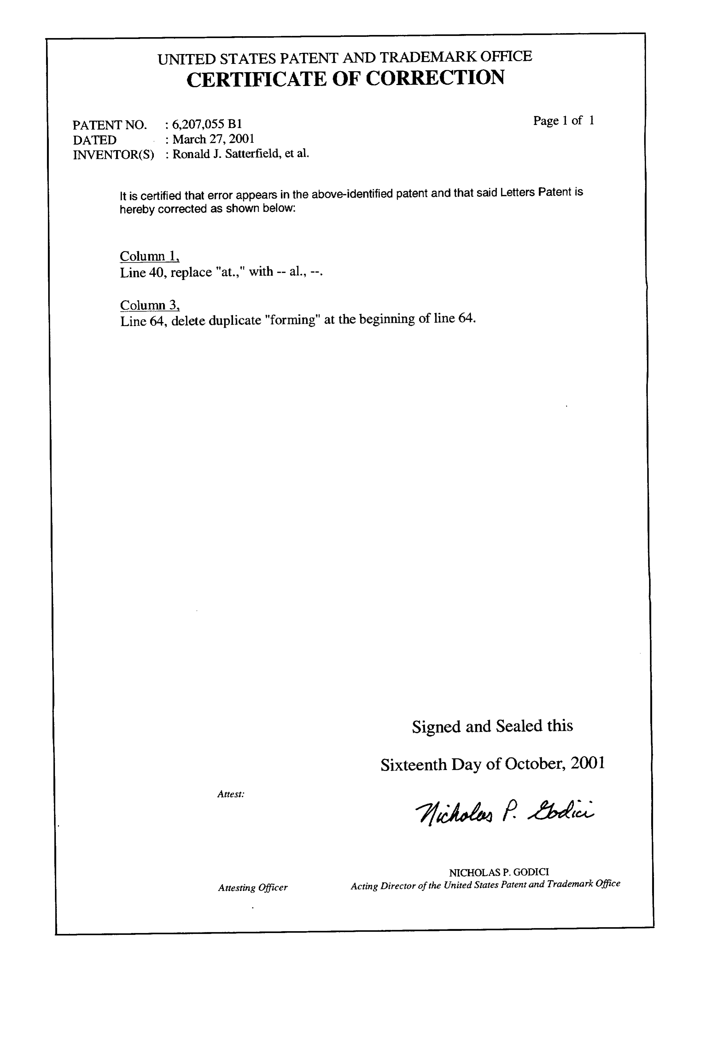
UNITED STATES PATENT AND TRADEMARK OFFICE
CERTIFICATE OF CORRECTION
PATENT NO. : 6,207,055 B1 Page 1 of 1
INVENTOR(S) : Ronald J. Satterfield, et al.
It is certified that error appears in the above-identified patent and that said Letters Patent is hereby corrected as shown below:
Column 1
Column 3
Line 64, delete duplicate "forming" at the beginning of line 64.
Signed and Sealed this
Sixteenth Day of October, 2001
7c44 fael
NICHOLASP. GODICI
Attesting Officer Acting Director of the United States Patent and Trademark Office
Provenance
- Collection
- Cited prior art
- Original PDF
- patentimages.storage.googleapis.com →
- Filed
- 1997-06-16
- Pages
- 18
- Method
- pdftotext (the PDF's own text layer) + pdftoppm 300dpi page scans
- Source
- Google Patents bibliographic record
- Granted
- 2001-03-27
- Inventors
- Ronald J. Satterfield; Thomas W. Yergovich; Idaho Research Foundation Inc
- Transcribed from
- patentimages.storage.googleapis.com →