patent · US6116221
Gasoline vapor purging system of internal combustion engine
12 September 2000
Page 1 — bibliographic record
United States Patent (19) 11 Patent Number: 6,116,221 Matsumoto et al. (45) Date of Patent: Sep. 12, 2000
54). GASOLINE WAPOR PURGING SYSTEM OF 5,746,187 5/1998 Ninomiya et al. ...................... 123/698 INTERNAL COMBUSTION ENGINE 5,765,541 6/1998 Farmer et al. .......................... 123/698 5,806,501 9/1998 Osanai .................................... 123/698 75 Inventors: Mikio Matsumoto; Masaya Furushou; 5,950,603 9/1999 Cook et al. ............................. 123/520 Shigeaki Kakizaki; Hiraku Ooba, all FOREIGN PATENT DOCUMENTS of Yokohama, Japan
73 Assignee: Nissan Motor Co., Ltd., Yokohama, 2-169834 6/1990 Japan. Japan 7-42588 2/1995 Japan.
No.: 09/112,443 2 300 278 A 10/1996 United Kingdom.
p 9 Primary Examiner Thomas N. Moulis 22 Filed: Jul. 9, 1998 Attorney, Agent, or Firm-Foley & Lardner 30 Foreign Application Priority Data 57 ABSTRACT Jul. 10, 1997 JP Japan .................................... 9-185144 In an internal combustion engine of gasoline direct injection (51) Int. Cl." ..................................................... F02M 37/04 type, there is arranged a gasoline vapor purging System. The 52 U.S. CI 123/520; 123/295 Vapor purging System has a vapor purging Section which -: -- -- s temporarily traps gasoline vapor produced in a fuel Supply 58 Field of Search ...........123,519,520, 3.s Section of the engine and feeds the gasoline vapor through s s s s a vapor purge conduit into an intake Section of the engine 56) References Cited upon operation of the engine. In the vapor purge conduit, there is installed an electrically actuated valve which con
k 5 The vapor purging System has further a control unit which R. only i al. . . . . . . . . . . . . . . . . . . . . . 5.3. controls operation of the valve So that a target purging rate 5616973 4f1997 Hara et all - - - - - - - - ... 123/520 of the gasoline vapor toward the intake Section is determined 5,626,122 5/1997 Azuma. ... 123,698 based on an amount of gasoline injected to each combustion 5,655,507 8/1997 Kawasaki ............. ... 123/698 chamber of the engine through an injector. 5,699,778 12/1997 Muraguchi et al. ..... ... 123/698 5,735,255 4/1998 Farmer et al. .......................... 123/698 14 Claims, 5 Drawing Sheets
CONTROL
UNT
N As Navy as Ayya Sasy 2 S Saw S 18
AMOSPHERE
Page 2
Drawing sheet — no readable text.
Page 3
Drawing sheet — no readable text.
Page 4
Drawing sheet — no readable text.
Page 5
Drawing sheet — no readable text.
Page 6
Drawing sheet — no readable text.
Page 7
GASOLINE WAPOR PURGING SYSTEM OF affected by the above-mentioned vapor purging and the INTERNAL COMBUSTION ENGINE exhaust gas recirculation (EGR). That is, if the stratified mixture becomes to have an outer layer whose air/fuel ratio
The contents of Japanese Patent Application 9-185144 is too high (viz., too lean) due to affection by the vapor filed Jul. 10, 1997 are hereby incorporated by reference. purging and/or the exhaust gas recirculation (EGR), appro BACKGROUND OF THE INVENTION priate combustion of the outer layer is not obtained, which 1. Field of the Invention increases a possibility of remaining unburned Substances in The present invention relates in general to evaporation the combustion chambers. While, if the stratified mixture emission controls (EEC) of motor vehicles powered by has a too low air/fuel ratio (viz., too rich mixture) in total, internal combustion engines, which prevent the escape of appropriate combustion of the mixture is not obtained also, gasoline vapors from the fuel tank and fuel Supply System, which increases a possibility of exhausting much Smoke and whether or not the engine is running More specifically, the thus increasing fuel consumption, present invention relates to a gasoline vapor purging System for use in an internal combustion engine of a gasoline direct 15 For Solving the above-mentioned drawbacks, a measure injection type. may be thought out wherein during combustion of the 2. Description of the Prior Art Stratified mixture, the vapor purging is inhibited or at least For preventing the escape of gasoline vapors from the fuel turned Down. However, in this case, the performance of the Supply Section Such as a fuel tank or the like, most vehicles gasoline Vapor purging System per Se is Sacrificed. That is, built during these days use an activated charcoal canister to fuel (viz., gasoline vapors) trapped by the charcoal canister trap the vapors when the engine is shut off. Upon restarting, can not be completely purged from the charcoal canister a flow of filtered air through the canister purges the vapors under operator of the engine, So that it tends occur that when from the charcoal. The mixture goes through a vapor purge the engine is Stopped, the canister exhibits its Saturation pipe feeding into an intake Section of the engine and it is condition in adsorbing vapors. In this case, gasoline vapor burnt in the engine. 25 generated thereafter can not be trapped is by the canister any
In a gasoline vapor purging System disclosed by Japanese longer, which permits escape of the vapor into the atmo Patent First Provisional Publication 7-42588, a purge control Sphere.
valve is used for controlling the flow off vapors in the vapor purge pipe in accordance with an operation condition of the SUMMARY OF THE INVENTION engine. That is, in the conventional vapor purging System, a target vapor purging rate (viz., target open degree of the It is therefore an object of the present invention to provide purge control valve) is determined in accordance with the a measure which is free of the above-mentioned drawbackS. flow rate of air (viz., intake air) led into the engine. According to the present invention, there is provided a However, hitherto, the vapor Surging System has been gasoline vapor purging System of an internal combustion given little thought in internal combustion engines of a type 35 engine of gasoline direct injection type, which optimally which can Switch between a So-called “Stoichiometric com carries out the vapor purging in accordance with the com bustion mode” wherein the engine operates on a mixture of bustion of the engine.
Stoichiometric air/fuel ratio and a So-called “lean combus tion mode” wherein the engine operates on a mixture of According to the present invention, there is provided a higher (or lean) air/fuel ratio. That is, to allow the engine to 40 engine ofvapor gasoline purging System for an internal combustion gasoline direct injection type. The System com operate in the lean combustion rode, it is necessary to increase the flow rate of the intake airby increasing the open prises a vapor purging Section which temporarily traps degree of a throttle valve. Thus, if the target vapor purging gasoline vapor produced in a fuel Supply Section of the rate is determined in accordance with the flow rate of the engine and feeds the gasoline vapor through a vapor purge intakes air like in case of the Publication 7-42588, the lean 45 conduit to an intake Section of the engine upon operation of combustion mode is forced to induce excessive vapor the engine; an electrically actuated valve installed in the purging, which tends to lower combustibility of the mixture Vapor purge conduit to control flow of the gasoline vapor in combustion chambers. toward the intake Section; and a control unit which controls In internal combustion engines operating on gasoline, operation of the valve So that a target purging rated of the there is a So-called "gasoline direct injection type' wherein 50 gasoline vapor directed toward the intake Section is deter fuel (viz., gasoline) is directly injected into combustion mined based on an amount of gasoline injected to each combustion chamber of the engine through an injector.
chambers. The engines of Such type disclosed by Japanese
Patent First Provisional Publications 62-191622 and According to the present invention, there is further pro 2-169834 have two combustion modes of early and late Vided a gasoline vapor purging control System for use with injection of fuel. That is, injection early in the intake Stroke 55 an internal combustion engine which has a vapor purging produces a homogeneous mixture for high-load conditions, Section which temporarily traps gasoline vapor produced in while the late injection delays the event until near the end of a fuel Supply System of the engine and feeds the same to an the compression Stroke to create a Stratified mixture for intake Section of the engine upon operation of the engine. low-load conditions. The Stratified mixture generally con The control System comprises first means for determining a Sists of a first layer of richer mixture which is easily ignited 60 target vapor purging rate based on an amount of fuel fed to by an ignition plug and a Second layer of leaner mixture each combustion chamber of the engine, Second means which is ignited by the burning of the first layer of mixture. which, when the engine operates on a Stratified lean mixture, Combustion of the stratified mixture realizes ultra-lean corrects the target vapor purging rate in accordance with a combustion and thus brings about improvement in fuel target air/fuel ratio of the mixture; and third means for economy due to reduction in pumping loSS. 65 Selectively controlling the vapor purging effected by the However, as is known, combustion of Stratified mixture is Vapor purging Section in accordance with the target vapor very Sensitive to a change in air/fuel ratio and thus easily purging rate and the corrected target Vapor purging rate.
Page 8
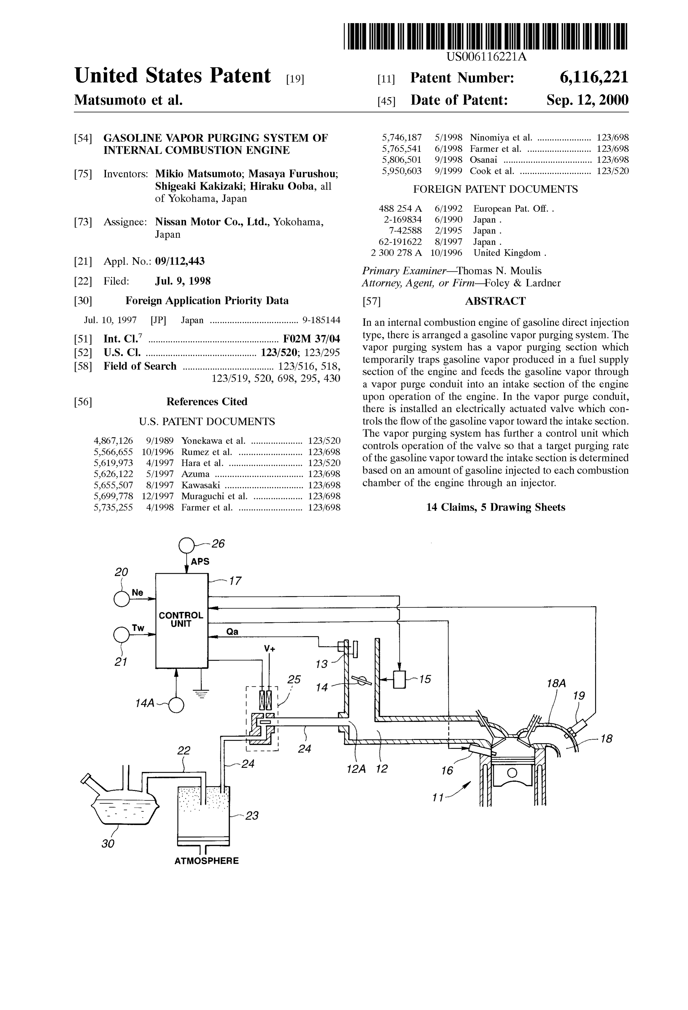
BRIEF DESCRIPTION OF THE DRAWINGS A crank angle Sensor 40 is installed in a distributor (not FIG. 1 is a Schematic view of a gasoline vapor purging shown), tion with which issues a crank angle signal in Synchroniza the engine Speed. By counting pends of the Signal
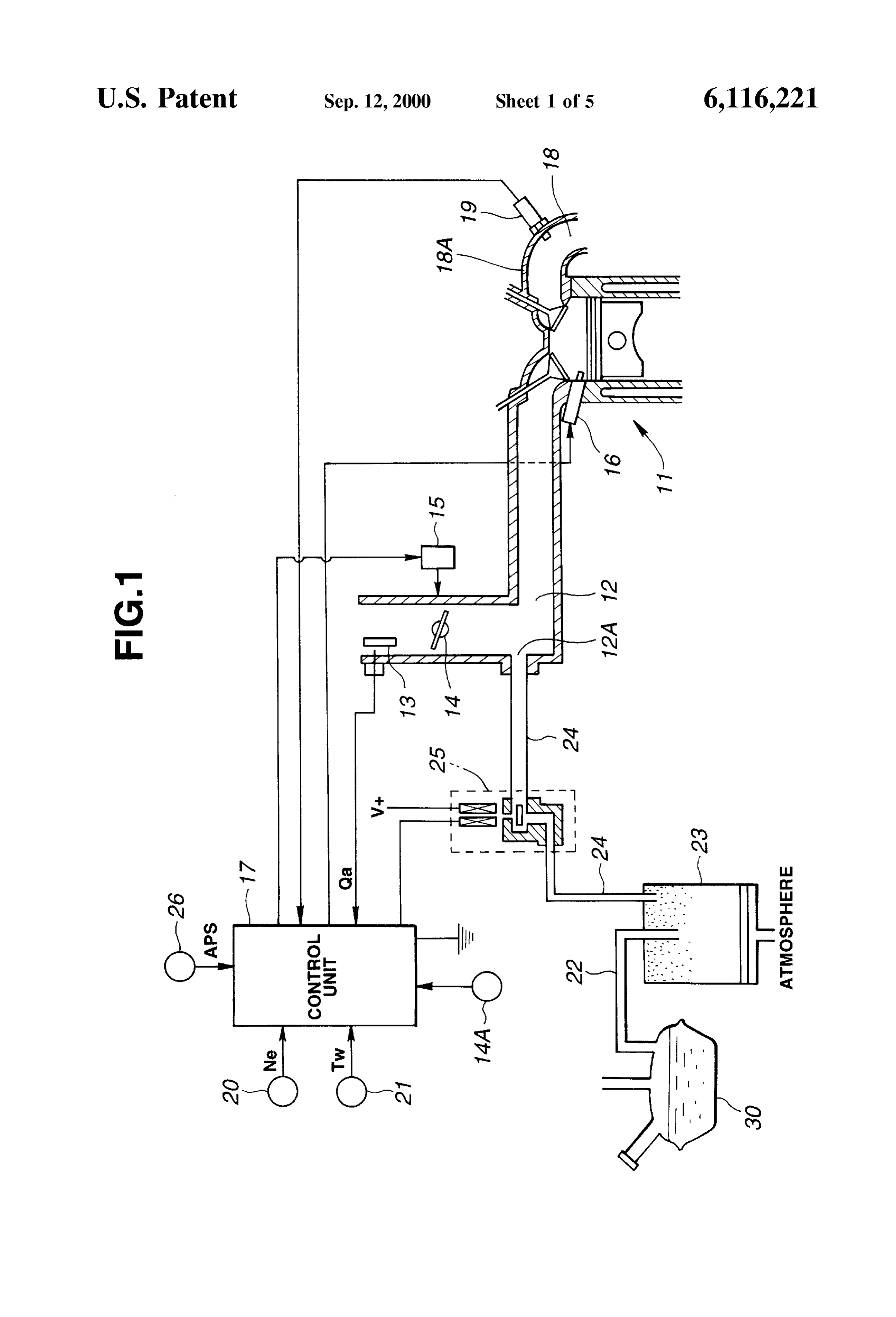
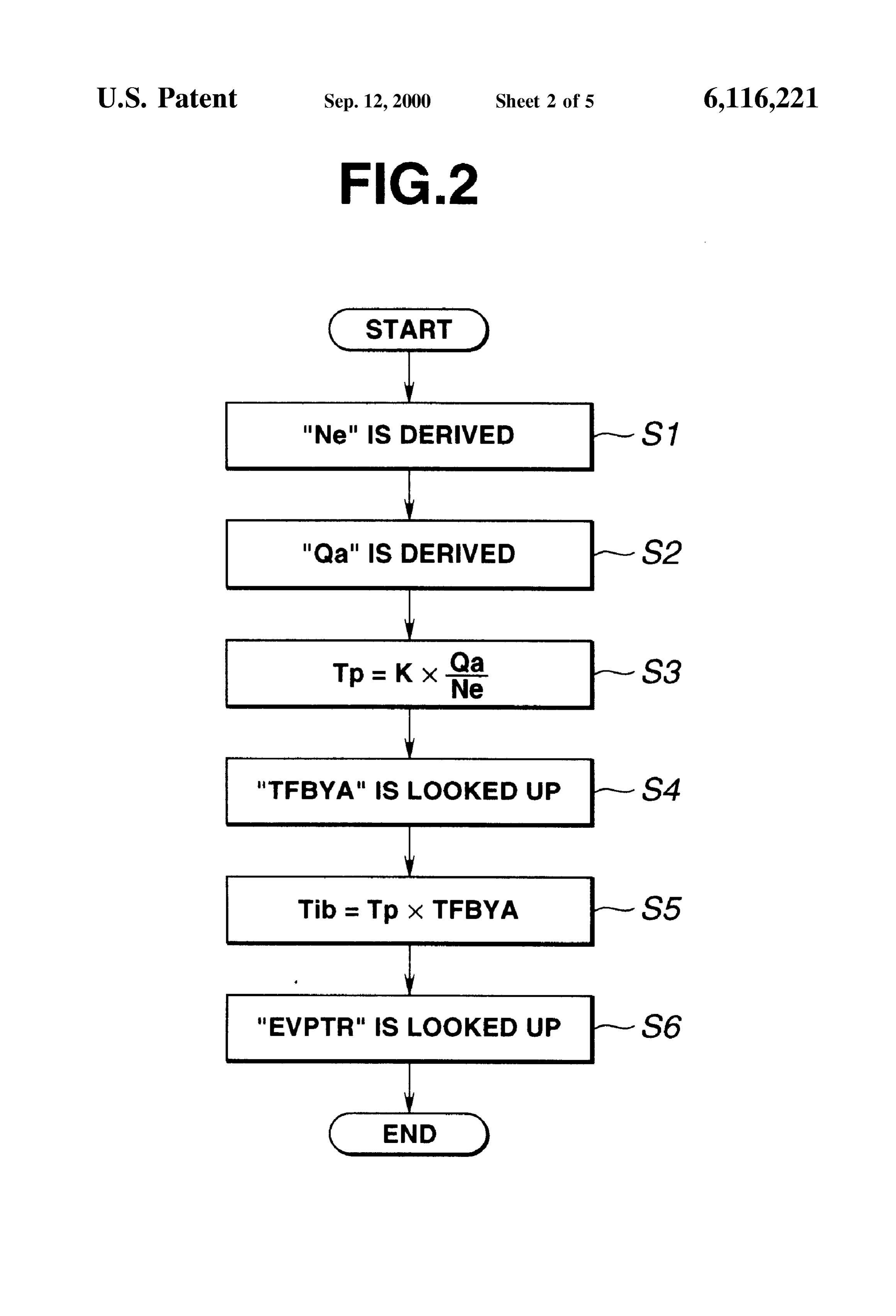
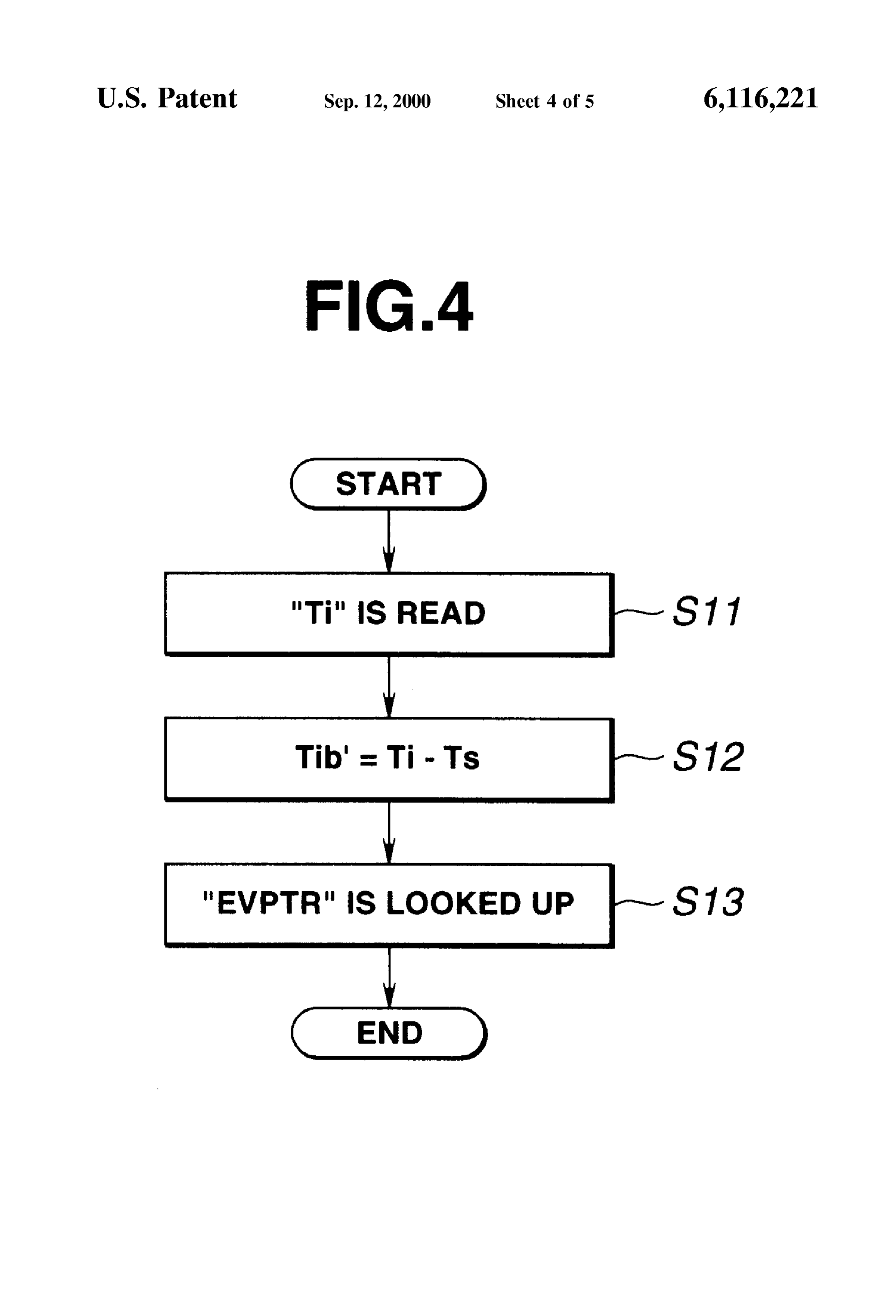
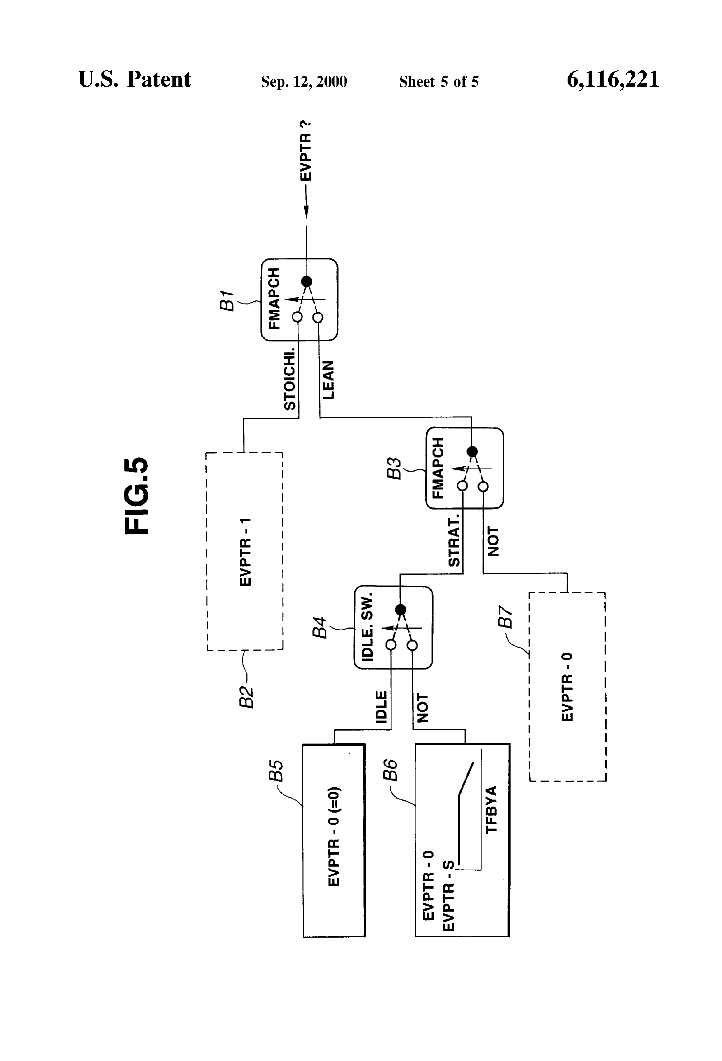
System according to the present invention, in a unit time, or by detecting the period of the base crank FIG. 2 is a flowchart showing programmed operation angle, the engine Speed "Ne' is detected. A temperature StepS eXecuted by a control unit for deriving a target purging sensor 21 is further provided which detects the temperature rate, “TW' of cooling water of the engine 11. FIG. 3 is one of data maps used for determining the target The information Signal front the accelerator sensor 26 purging rate, which shows a relationship between an engine represents a depression degree "APS' by which an accel Speed, an amount of injected fuel, and a target purging rate; erator pedal (not shown) is depressed by a driver. It is to be FIG. 4 is a flowchart similar to FIG. 2, but showing the noted that the depression degree “APS' corresponds to an other method for deriving the target purging rate, and engine output torque needed by the driver. FIG. 5 is a flow table showing work steps executed by a Gasoline vapors from a fuel tank 30 are led to an activated control unit for determining various target purging rates. 15 charcoal canister 23 through a vapor pipe 22, So that the Vapors are contemporarily trapped by the canister 23. An
DETAILED DESCRIPTION OF THE upper space in the canister 23 is connected through a vapor INVENTION purge pipe 24 to a purge port 12A which is formed in the
Referring to FIG. 1 of the drawings, there is shown in united upstream part of the intake manifold of the intake Schematic form a gasoline vapor purging control System of section 12 downstream of the throttle valve 14. To the purge the present invention, which is incorporated with an internal pipe 24, there is connected a purge control valve 25 which combustion engine 11 of a gasoline direct injection type. is controlled by the control unit 17. That is, open timing and In an upstream Single conduit part of an air intake Section open period of the valve 25 are controlled by the control unit 12 of the engine 11, there are installed an air flow meter 13 used asa duty-ratio 17 in control manner, A Stepping motor may be the control valve 25.
and a throttle valve 14 which is positioned downstream of 25 In the computer of the control unit 17, the following the air flow meter 13 as shown. Although not shown in the programmed operation StepS are executed for controlling the drawing, an air cleaner is connected to an upstream end of purging of gasoline Vapors.
the Single conduit part of the intake Section 12, by which air introduced into the intake Section 12 is cleaned. The intake FIG. 2 is a flowchart showing operation Steps for deriving Section 12 has an intake manifold which comprises a united a target purging rate “EVPTR based on an amount “Tib” of part constituting the upstream Single conduit part and a injected fuel, For ease of description, the amount “Tib' will plurality of branches extending from the united part to intake be referred to as “fuel injection amount” in the following. ports of respective combustion chambers. The air flow meter That is, at step S1, the engine speed “Ne” is derived from 13 measures the flow rate “Oa' of the intake air, that is, the the Signal issued from the crank angle Sensor 20. At Step S2, amount of intake airper unit time. The throttle valve 14thus 35 the flow rate “Qa' of intake air is derived from the signal controls the flow rate “Qa' of the intake air. Electromagnetic issued from the air flow meter 13. At step S3, a basic amount fuel injectors 16 are arranged to directly inlet metered fuel “Tp” of injected fuel for each combustion chamber is into respective combustion chambers of the engine 11. Each derived from the following equation:
fuel injector 16 is controlled by a control unit 17 which has Tp =kxQa/Ne (1) a microcomputer installed therein. That is, by processing 40 various information signals applied thereto from various wherein:
Sensors, the control unit 17 issues an instruction pulse signal k: constant to each of the fuel injectors 16 to control the amount of fuel In fact, the basic amount “Tip” is the amount of injection injected into the corresponding combustion chamber. fuel which brings about a Stoichiometric air/fuel ratio. A throttle valve control device 15 is provided, which can 45 At step S4, a target equivalence ratio “TFBYA' is looked electronically control the open degree of the throttle valve up from a data map which shows a relationship between 14 in accordance with an instruction signal applied thereto various operation conditions of the engine and equivalence from the control unit 17. For this control, an information ratios. The operation conditions of the engine are a Stoichio Signal from an accelerator Sensor 26 is also ted to the control metric combustion condition wherein the engine operates on unit 17. That is, through the throttle valve control device 15, 50 a mixture of Stoichiometric air/fuel ratio, a lean combustion the open degree of the throttle valve 14 is controlled in condition wherein the engine operates on a lean mixture, a accordance with the engine operation condition determined Stratified charge combustion condition wherein the engine based on the information Signals from the Sensors. For operates on a Stratified charge of mixture, a homogeneous detecting the open degree of the throttle Valve 14, a throttle charge combustion condition wherein the engine operates on sensor 14A is provided which feeds the on control unit 17 55 a homogeneous charge of mixtures high/low load combus with an information Signal representing the open degree of tion condition wherein the engine operates on a mixture the throttle valve 14. In place of the throttle sensor 14A, an under high/low load, etc.,.
idling Sensor may be used. At step S5, a fuel injection amount “Tib' is derived from In an exhaust passage 18 of the engine 11, there is the following equation:
installed an oxygen Sensor 19 of which information Signal is 60 Tib=TpxTFBYA (2) fed to the control unit 17, More specifically, the oxygen sensor 19 is installed in an united pare of branches of the Then, at step S6, a target purging rate “EVPTR is looked exhaust manifold 18A. AS is known, by measuring en up from a data map which, as is S from FIG. 3, shows a concentration in the exhaust gas by the oxygen Sensor 19, an relationship between the fuel injection amount “Tib', engine air/fuel ratio of the mixture fed to the engine 11 is detected. 65 speed “Ne” and target purging rate “EVPTR'. Thus, the oxygen Sensor 19 is also known as an air/fuel ratio AS is understood from the above, in the present invention, SCSO. the target purging rate “EVPTR is determined based on the
Page 9
S 6 amount “Tib” of fuel actually injected into the combustion operating under Stoichiometric combustion mode, block B2 chamber, that is, based on a target torque of the engine. In is Selected, while, when it is judged that the engine is other words, in the present invention, the target purging rate operating underlean combustion mode, block B3 is Selected. “EVPTR” is not determined on the basic amount “Tp” of At block B2, a target purging rate “EVPTP-1 for the injected fuel which brings about a Stoichiometric air/fuel Stoichiometric combustion mode is looked up from a cor ratio. responding data map, such as that shown in FIG. 3. While, Accordingly, even when, under operation of lean com at block B3, judgment is carried out as to whether the lean bustion mode, the open degree of the throttle valve 14 is combustion is a Stratified combustion or a non-Stratified further increased for achieving a target lean mode combus combustion. That is, for example, by looking up a data map tion and thus the flow rate of intake air fed to each com “FMAPCH' which represents relationship between the bustion chamber is increased, it is possible to fit the vapor engine operation condition (engine Speed, torque produced, purging rate to a combustion condition of the engine, that is, etc.) and combustion type, Such judgment is achieved. to the amount of fuel actually injected to each combustion When it is judged that the seen combustion is the stratified chamber. Accordingly, according to the present invention, combustion, block B4 is Selected, while, when it is judged undesired excessive vapor purging, which would occur in 15 that the lean combustion is the non-stratified (combustion, the above-mentioned conventional is vapor purging control block B7 is selected. At block B7, that is, when the engine System in Such condition, is Suppressed or at least mini is operating on a non-Stratified lean air/fuel mixture, a target mized. purging rate “EVPTR-0” is looked up from a corresponding If desired, the fuel injection amount “Tib” may be derived data map, such as that shown) in FIG. 3. At block B4, from other methods. That is, the fuel injection amount “Tib' judgment is carried out as to whether the engine is idling or can be derived from a pulse duration “Ti” of a fuel injection not, That is, when the throttle Sensor 14A issues a signal pulse Signal which is issued from a control unit under normal representing 0 (zero) open degree of the throttle valve 14, fuel injection operation of the engine. AS is known, the fuel block B5 is Selected judging that the engine is under idling. injection pulse signal issued under Such normal operation of While, when the throttle sensor 14A issues a signal repre the engine is provided in accordance with the existing 25 senting the throttle valve 14 being open, block B6 is selected condition of the engine, that is, with respect to a target judging that the engine is not under idling. At block B5, that equivalence ratio, various correction factors, etc.,. is, when the engine is idling on a Stratified lean mixture, the FIG. 4 is a flowchart showing programmed operation target purging rate “EVPTR-0” is set to 0 (zero) having steps executed for deriving the target purging rate “EVPTR” regard to a fact that under Such condition the combustibility from the pulse duration “Ti”. of the mixture is easily affected by the vapor purging. While, At step S11, the pulse duration “Ti” of a fuel injection at block B6, that is, when the engine is normally operating pulse signal is read. Usually, the pulse duration "Ti” is on a stratified lean mixture, a target purging rate “EVPTR-0” determined from the following equation: is looked up front a corresponding data map, Such as that Ti=TpxCOEFXTFBYA+TS (3) shown in, FIG. 3. For deriving the rate “EVPTR-0”, the 35 above-mentioned operation steps of FIG. 2 or FIG. 4 are wherein: executed. AS is known, the influence of vapor purging to the Tp: basic amount of injected fuel for achieving Sto combustion of Stratified lean mixture under normal opera ichiometric air/fuel ratio; tion of the engine is very low as compared faith that to the COEF: coefficient; combustion of the same under idling operation of the engine, TFBYA: target equivalent ratio; 40 but high as compared with that to the combustion of homo TS: invalid fuel injection pulse. geneous lean mixture under normal operation of the engine. At step S12, a fuel injection amount “Tib' is derived from Thus, as is seen from the map illustrated in block B6, When the following equation: the target equivalence ratio “TFBYA' exceeds a predeter mined level, that is, when a target air/fuel ratio under the
Tb'-T-Ts (4) 45 Stratified combustion of lean mixture becomes higher (viz., leaner) than a predetermined level, a certain limitation is wherein: applied to the target purging rate “EVPTR-0. That is, the Ts: invalid pulse duration. target purging rate “EVPTR-0” is saturated at the level of At step S13, a target purging rate “EVPTR is looked up “EVPTR-S'. More specifically, because, with increase of from a data map which, as is understood from FIG. 3, shows 50 the target air/fuel ratio (viz., with decrease of the target a relationship between the fuel injection amount “Tib', equivalence ratio “TFBYA', or as the mixture becomes engine speed Ne and target purging rate “EVPTR'. leaner), the influence of the vapor purging to the combustion FIG. 5 is a flow table showing work steps executed by the in becomes higher, the target purging rate “EVPTR-0” has control unit 17 for deriving the target purging rate. AS will the upper limitation of “EVPTR-S". become apparent as the description proceeds, the target 55 AS is known, in the homogeneous charge combustion, purging rate changes depending on the operation condition fuel is entirely spread in the combustion chamber to produce of the engine, that is, whether the engine operates under a homogeneous air/fuel mixture, while, in, the Stratified Stoichiometric combustion mode, lean combustion mode, charge as combustion, fuel is partially spread in the com Stratified mixture combustion mode, homogeneous combus bustion chamber to produce an easily combustible air/fuel tion mode or So. 60 mixture at only a given portion of the chamber. Accordingly, At block B1, judgment is carried out as to whether the in the Stratified charge combustion, fuel in the purged vapor engine is operating under Stoichiometric combustion mode from the charcoal canister affects the combustion of tire or lean combustion mode. That is, for example, by looking mixture relatively hard. This phenomenon becomes much up a data map “FMAPCH' which represents a relationship Severe ashen the mixture becomes leaner, that is, when the between the engine operation condition (engine speed, 65 fuel injection amount becomes leSS. Thus, if the target torque produced, etc.) and combustion mode, Such judg purging rate “EVPITR-0” is determined simply based on the ment is achieved. When it is judged that the engine is fuel injection amount “Tib', Such undesired phenomenon
Page 10
can not be eliminated or lowered. However, if the target So made that the target purging rate reduces with increase of purging rate “EVPTR-0” is processed to have the upper the rate of EGR.
limitation of “EVPTR-S' in Such a manner as is described Furthermore, if desired, the targets purging rate “EVPTR' hereinabove, Such undesired phenomenon can be eliminated may be corrected in accordance with the amount “OGA' of or at least minimized. operation gas which is represented by the following equa In the control unit 17, an open degree of the purge control tion:
Valve 25, more Specifically, a duty ratio of an instruction OGA=(Qa+QEGR+QPURGE)/FR (5) pulse signal applied thereto which achieves the target purg ing rate “EVPTR” (viz., EVPTR-0 or EVPTR-1) is looked wherein:
up from a corresponding data map. When receiving Such Qa: amount of air measured by air flow meter 13, instruction pulse signal from the control unfit 17, the purge QEGR: amount of exhaust gas fed back to combustion control valve 25 controls its open timing and open period. chamber,
AS is described hereinabove, the present invention, the QPURGE: amount of air in gasoline vapor, target purging rate is determined based on the fuel injection FR: rate of amount of fuel. amount “Tib' or Tib' irrespective of whether the combus 15 What is claimed is:
tion is a Stratified lean mixture combustion or a honogeneous 1. A gasoline vapor purging System for an internal com lean mixture combustion. Accordingly, even then, under a bustion engine of gasoline direct injection type, comprising: lean mixture combustion mode, for achieving a target air/ a vapor purging Section which temporarily traps gasoline fuel ratio in the mode, the open degree of the throttle valve Vapor produced in a fuel Supply Section of the engine 14 is increased by a degree greater than that in cast of a and feeds the gasoline vapor through a vapor purge Stoichiometric combustion mode to achieve a target lean conduit into an intake Section of the engine upon air/fuel ratio and thus the amount of air fed into each operation of the engine;
combustion chamber is increased, the gasoline vapor purg an electrically actuated valve installed in Said vapor purge ing is appropriately carried out in accordance with the conduit to control the flow of the gasoline vapor toward combustion condition in the combustion chamber without 25 Said intake Section; and being affected by the increased air amount. In other words, a control unit which controls operation of Said valve So under Such condition, the vapor purging rate is determined that a target purging rate of the gasoline vapor directed in accordance with the fuel injection amount “Tib' or “Tib'. toward the intake Section is determined based on an That is, undesired excessive vapor purging, which would amount of gasoline injected to each combustion cham lower combustibility of the learn mixture, is eliminated or at ber of the engine through an injector and based on a least minimized. predetermined relationship between gasoline amount Under a stratified lean mixture combustion mode, the and purging rate.
target purging rate “EVPTR is determined in accordance wherein, when said engine operates on a stratified lean with the target equivalence ratio “TFBYA' (or target air/fuel mixture, Said control unit corrects Said target purging ratio), Thus, even under Such mode wherein the combustion 35 rate in accordance with a target air/fuel ratio of the of lean mixture would be easily affected by the vapor mixture, purging, Satisfied combustibility of the mixture is kept while wherein the predetermined relationship is based in part on assuring optimal gasoline vapor purging. Thus, as compared a particular engine operation mode. with the above-mentioned conventional technique wherein 2. A gasoline vapor pursing System as claimed in claim 1, under Stratified lean mixture combustion the vapor purging 40 in which when said engine operates on a Stratified lean is inhibited or at least turned down, the invention can exhibit a marked performance in the vapor purging. In other words, mixture, Said control unit correctS Said target purging rate in in the invention, the vapor purging and the combustibility of accordance with a target air/fuel ratio of the mixture. the Stratified lean mixture are both improved at the same in 3.which A gasoline vapor purging System as claimed in claim 2, said target purging rate and the corrected target time. That is, even under the Stratified lean mixture com 45 bustion mode, the vapor purging is Sufficiently carried out. concentration are purging rate each corrected in accordance with the of the gasoline vapor in Said vapor purge
If desired, the target purging rate “EVPTR” (viz., conduit.
EVPTR-0, EVPTR-1, EVPTR-S) may be corrected in accor 4. A gasoline vapor purging System for an internal com dance with the concentration of the purged vapor. For bustion engine of gasoline direct injection type, comprising: example, the correction is So made that the target purging 50 rate reduces with increase of the concentration of the vapor. a vapor purging Section which temporarily traps gasoline For measuring the concentration of the vapor, a hydrocarbon Vapor produced in a fuel Supply Section of the engine concentration Sensor is mounted in the vapor purge pipe 24 and feeds the gasoline vapor through a vapor purge (see FIG. 1). Furthermore, the concentration of the vapor conduit into an intake Section of the engine upon may be derived from a difference between an air/fuel ratio 55 operation of the engine;
correction, factor “C.” Set for a feedback control of the an electrically actuated valve installed in Said vapor purge engine under a mode wherein the vapor purging is not conduit to control the flow of the gasoline vapor toward carried out and another air/fuel ratio correction factor f3” Set Said intake Section; and for the feedback control of the engine under a mode wherein a control unit which controls operation of Said valve So the vapor purging is carried out. AS is known, in the 60 that a target purging rate of the gasoline vapor directed feedback control of the engine, by processing an information toward the intake Section is determined based on an Signal issued from an oxygen Sensor 19 (or air/fuel ratio amount of gasoline injected to each combustion cham Sensor), the existing air/fuel ratio of mixture is controlled to ber of the engine through an injector, a Stoichiometric value. in which when said engine operates on a Stratified lean Furthermore, if desired, the target purging rate “EVPTR' 65 mixture, Said control unit corrects Said target purging may be corrected in accordance with the rate of exhaust gas rate in accordance with a target air/fuel ratio of the recirculation (EGR). That is, for example, the correction is mixture, and
Page 11
in which Said target purging rate and the corrected target a control unit having:
purging rate are each corrected in accordance with an a fuel delivery calculating Section to calculate an amount of exhaust gas which is fed back from an amount of fuel delivered to the engine; exhaust Section of the engine to Said intake Section. a purge amount calculating Section to calculate an 5. Agasoline vapor purging System as claimed in claim 2, amount of gasoline vapor purged to the intake air in which Said target purging rare and the corrected target passage as a function of the calculated amount of purging rate are each corrected in accordance with an delivered fuel and based on a predetermined rela amount “OGR' of operation gas, said amount “OGR' being tionship between fuel amount and purging rate; and represented by the following equation: a valve controlling Section to control the operation of the purge control valve based on the calculated amount of the gasoline vapor, wherein, when Said engine operates on a Stratified lean wherein: mixture, Said control unit corrects Said purge control Qa amount of air measured by air flow meter, 15 Valve in accordance with a target air/fuel ratio of the QEGR: amount of exhaust gas fed back to combustion mixture, and chamber, wherein the predetermined relationship is based in part on QPURGE: amount of air in gasoline vapor, a particular engine operation mode. FR: rate of amount of fuel. 9. A gasoline vapor purging System as claimed in claim 8, 6. Agasoline vapor purging System as claimed in claim 2, in which said engine is of a type which can Switch between wherein the controller further comprises a combustion con trolling Section Selectively controlling one of Stratified com a Stratified charge combustion mode wherein the engine operates on a Stratified charge of lean mixture and a homo bustion 10. A and homogeneous combustion.
gasoline vapor purging method for an internal geneous charge combustion mode wherein the engine oper combustion engine, comprising: ates on a homogeneous charge of lean mixture. 25 7. Agasoline vapor purging control System for use with an calculating an amount of fuel delivered to the engine; internal combustion engine which has a vapor purging calculating an amount of gasoline vapor purged from a Section which temporarily traps gasoline vapor produced in canister to an intake air passage of the engine as a a fuel Supply System of the engine and feeds the Same to an function of the calculated amount of the fuel and based intake Section of the engine upon operation of the engine, on a fixed relationship between fuel amount and purg Said control System comprising: ing rate, and first means for determining a target vapor purging rate controlling a purge control valve based on the calculated based on an amount of fuel fed to each combustion amount of the gasoline vapor, the purge control valve chamber of the engine and based on a predetermined being installed in a conduit connecting the canister and relationship between fuel amount and purging rate; 35 the intake air passage,
Second means which, when Said engine operates on a wherein, when Said engine operates on a Stratified lean Stratified lean mixture, corrects Said target vapor purg mixture, Said control unit corrects Said purge control ing rate in accordance with a target air/fuel ratio of the Valve in accordance with a target air/fuel ratio of the mixture, and mixture, and third means for Selectively controlling the vapor purging 40 wherein the fixed relationship is based in part on a effected by Said vapor purging Section in accordance particular engine operation mode. with the target vapor purging rate and the corrected 11. A gasoline vapor purging System as claimed in claim target Vapor purging rate. 1, wherein the predetermined relationship is obtained from 8. A gasoline vapor purging System for an internal com 45 a data map.
bustion engine, comprising: 12. Agasoline vapor purging control System as claimed in a canister connected to a gasoline Supply device, the from a7,data claim wherein the predetermined relationship is obtained map.
canister trapping a gasoline Vapor, 13. A gasoline vapor purging System as claimed in claim an intake air passage connected to the engine, through 8, wherein the predetermined relationship is obtained from
a data map.
a vapor purge conduit connecting the canister and the 14. A gasoline vapor purging method as claimed in claim intake air passage, 10, wherein the fixed relationship is obtained from a data a purge control valve installed in the vapor purge conduit map.
to control the flow of gasoline vapor from the canister to the intake air passage; and
Provenance
- Collection
- Cited prior art
- Original PDF
- patentimages.storage.googleapis.com →
- Filed
- 1998-07-09
- Pages
- 11
- Method
- pdftotext (the PDF's own text layer) + pdftoppm 300dpi page scans
- Source
- Google Patents bibliographic record
- Granted
- 2000-09-12
- Inventors
- Mikio Matsumoto; Masaya Furushou; Shigeaki Kakizaki; Hiraku Ooba; Nissan Motor Co Ltd
- Transcribed from
- patentimages.storage.googleapis.com →